2.25Member Loads
Member loads (see Figure 2-13) can be point loads, distributed (uniform), moment (concentrated), left triangle, right triangle, and temperature loads. For the first five types, the orientation, direction, magnitude, point of application, and length of load (if applicable) must be defined. For temperature loads, the change in temperature and the distance between two surfaces must be input.
Member loads can be defined in the local (member) coordinate system, the global coordinate system, or acting on the global projection of the member. The direction of a load is one of the axes in reference to the orientation that is specified. Loads are considered positive if they act in the positive direction of an axis regardless of the orientation. In the local orientation, a rule of thumb is that positive loads tend to rotate the member counter-clockwise about its end joint (J2).
The intensity of a load is its magnitude. For left- or right-triangular loads, it is the magnitude of the load at the right end, or at the left end, respectively.
The point of application of a load is input as a ratio of the load location from joint J1 to the member length. Similarly, the length or extent of a load (uniform and triangular loads) is also input as a ratio of the load length to the member length. This way, a load can be applied to several members regardless of their length, and no change to the load data is required if the member length changes.
Temperature loads can be used to analyze the behavior of the structure when members are subject to a change in temperature. Change in temperature can be uniform on all the surfaces of a member (e.g. when the ambient temperature around the member changes). In this case, the member is subjected to axial stresses caused by its expansion or contraction. The change in temperature can also be different for opposite sides of a member (e.g. when the sun shines on one surface while the other surface is in the shade), in which case the member is subjected to bending, in addition to axial stresses due to the differential expansion or contraction of the two surfaces.
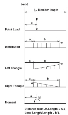
Figure 2.13 Types of Member Loads
To define a temperature load, you need to input the member thickness or the distance between the two surfaces that experience change in temperature, the top or right surface (Δtop), and the bottom or left surface (Δbot). The top surface refers to the member side that has the lower local y-coordinate. The right surface (for space frames only) refers to the member side that has the lower z-coordinate.