3.39Define Rigid-end Offsets
By default, the member length used in stiffness computations is the start joint-to-end joint length (center-to-center length). To account for the finite-support width and force the program to use the clear member length, use the Process/Rigid-end Offsets command to assign a half-support width at a member end. The member is assumed to be rigid within that width. This command is available for frame structures only.
•From the Process menu, select Rigid-end Offsets. The dialog box Figure 3-28 appears.
•From the MEMBER LIST list box, select the member to input rigid-end offsets for.
•Enter the support half width at the member start joint and end joint, Di and Dj, respectively, in the corresponding text boxes.
•Choose the ADD button. The data entered are added to the list box at the bottom.
•Repeat the three steps above for each rigid-end offset entry you have.
•To edit an entry that has been added to the list box, select that entry from the list box, modify its values, and choose the MODIFY button.
•To remove an entry that has already been added to the list box, select that entry from the list box and choose the DELETE button.
•Choose the OK button.
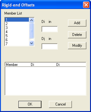
Figure 3-28 Rigid-end Offsets dialog box