5.33Compute Lateral Loads
Lateral loads (wind or seismic) may automatically be computed by spCad using the Options/Lateral Loads command. Since the equivalent static loads depend on the geometry of the structure, this option should be used after the entire structure is defined.
•From the Options menu, choose Lateral Loads. The dialog box of Figure 5-25 appears.
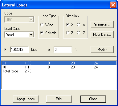
Figure 5-25 Lateral Loads dialog box
•UBC code is available for the English units system and NBC is available for the Metric system.
•From the LOAD CASE drop-down list, select the load case under which the lateral load should be included.
•From the LOAD TYPE group, select WIND or SEISMIC.
•From the DIRECTION group, select the direction in which the load is applied.
•To input the code-related parameters, choose the PARAMETERS button. A dialog box that depends on the selected code and load type appears (see description on the following pages).
•To modify the computed floor weights or dimensions, choose the FLOOR DATA button. The dialog box in Figure 5-26 appears. In this box you may change the width, depth, or weight of a floor. Input values may not be less than computed values.
•After all data are input, the computed loads and their point of action are displayed in the list box. For seismic loads, the load point of application is the center of mass (Xm, Zm). For wind loads, it is the center of the floor projected dimension in each direction (Xf, Zf).
•You may edit the forces or edit their location by specifying an eccentricity measured from the load point of application. To do so, select the item in the list box, edit the values in the text boxes, and choose the MODIFY button.
•To assign the loads to the floors, choose the APPLY LOADS button.
•To obtain a printout of the lateral loads, choose the PRINT button.
•In the GROUND ELEVATION text box, input the elevation of ground level from the origin in the Y direction (default value is the coordinate of the lowest XZ plane). Lateral loads will not be applied to the floors below the Ground Elevation.
•In the TOP ELEVATION text box, input the top of building elevation (if different than computed) from the origin in the Y direction. This is to account for parapets that may exist on the roof. The additional height will be considered in computing the wind load on the top floor. This value may not be less than the top floor elevation.
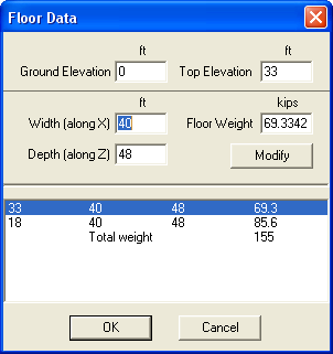
Figure 5-26 Floor Data dialog box
•To modify a floor data, select the level from the list box, edit its width, depth, or weight, and choose the MODIFY button. Input values may not be less than computed values.
•Choose the OK button. The forces in the lateral loads box are updated.
•Enter the basic wind speed, v [Figure No. 23-1 of the Code].
•Enter the windward and leeward pressure coefficients, Cq.
•The stagnation pressure, qs, is computed based on the input basic wind speed, v, [Table 23-F of the Code] and displayed.
•From the EXPOSURE group, select an exposure, B, C, or D [Sec. 2312 of the Code].
•From the OCCUPANCY group, select an occupancy type, ESSENTIAL, HAZARDOUS, SPECIAL, or STANDARD. The importance factor, I, is computed [Table 23-L of the Code] and displayed. To input a different I value, select the I= option and enter its value. UBC 1991, Seismic Parameters.
•From the ZONE group, select the applicable seismic zone, 1, 2A, 2B, 3, or 4 [Figure 23-2 of the Code]. The corresponding Z factor is displayed.
•From the SOIL TYPE group, select the applicable type, S1, S2, S3, or S4 [Table 23-J of the Code]. The site coefficient, S, is displayed. To input a different S value, select the S= option and enter its value.
•From the OCCUPANCY group, select an occupancy type, ESSENTIAL, HAZARDOUS, SPECIAL, or STANDARD. The importance factor, I, is computed [Table 23-L of the Code] and displayed. To input a different I value, select the I= option and input its value.
•From the STRUCTURE group, select the structure type, concrete momentresisting frame, steel moment resisting frame, or other [Sec. 2334(b)2A of the Code]. The Ct coefficient is displayed. To input a different Ct value, select the Ct= option and enter its value.
•From the LATERAL LOAD-RESISTING SYSTEM group, select a system type [Table 23-O of the Code]. The Rw coefficient is displayed. To input a different Rw value, select the Rw= option and enter its value.
•Based on the selected options, the structural period is computed [Eq. (34-3) of the Code] and displayed. If different than that computed, enter the value of the period, T.
•The top level force, Ft, and the base shear, V, are computed [Sec. 2334(d) of the Code] and their ratios to the total weight, W, are displayed. These values may not be modified.
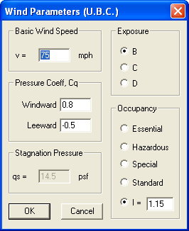
Figure 5-27 UBC Wind Parameters
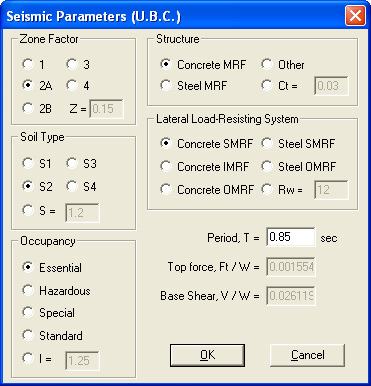
Figure 5-28 UBC Seismic Parameter
•Enter the wind speed, v*.
•From the EXPOSURE group, select A, B, or C [NBC Supplement Commentary B].
•Enter the pressure coefficient, Cp, for the windward and the leeward surfaces [NBC Supplement, Commentary B].
•Based on the input wind speed, the wind pressure, q, is computed [NBC Supplement, Commentary B] and displayed. If different than computed, enter its value.
•Enter the gust factor, Cg [Sec. 4.1.8.1(6) of the Code].
•The exposure factor for the leeward surface, Ce, is computed [NBC Supplement, Commentary B] and displayed. If different than computed, enter its value.
•Enter the acceleration-related seismic zone factor, Za*.
•Enter the velocity-related seismic zone factor, Zv*.
•Enter the zonal velocity ratio, v*.
•Enter the structural period, T.
•Based on the input Za, Zv, and T, the seismic response factor, S, is computed [Table 4.1.9.A of the Code] and displayed. If different than computed, enter its value.
•Enter the force modification factor, R [Table 4.1.9.B of the Code].
•From the IMPORTANCE group, select the appropriate category. The importance factor, I, is displayed [Table 4.1.9.1(10) of the Code]. To input a different I value, select the I= option and enter its value.
•From the FOUNDATION group, select the appropriate type. The foundation factor, F, is displayed [Table 4.1.9.C of the Code]. To input a different F value, select the F= option and enter its value.
•*"Design Data for Selected Locations in Canada", Chapter 1, NBC Supplement.
•The top level, Ft, and the minimum lateral seismic force, V, are computed and their ratios to the total weight are displayed. These values may not be modified
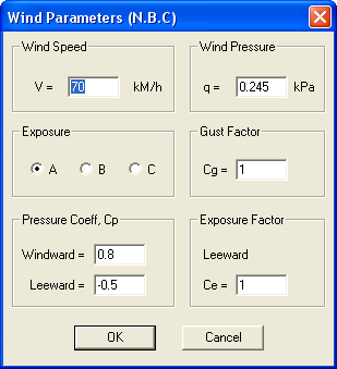
Figure 5-29 NBC Wind Parameters
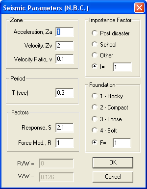
Figure 5-30 NBC Seismic Parameters