8.1Problem Description
The model is a 17-story building frame structure. The elevation and typical floor plans are shown in Figure 8-1. All beams are 24"x24" and of 4 ksi lightweight concrete (115 pcf). All columns are 30"x30" and of 5 ksi normal weight concrete (145 pcf).
All X beams have a point load of 20k (dead) and 15k (live) located at midspan. All Z beams have a uniform load of 2.15k/ft (dead) and 1.75 k/ft (live) over the entire span. Wind loads per UBC are also applied in the X direction above the first floor. All columns are fixed at the base and all floors are assumed to have a rigid diaphragm.
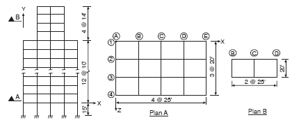
Figure 8-1 Floor Plan
The material and section properties of the columns (normal weight concrete and 30x30 section) will be assigned to the DEFAULT values.
To generate the model geometry, we will start with the first floor, draw the four beams along line "1" and then copy those beams in the +ve Z-direction, three times, at an offset of 20 ft. This will generate the beams along "2", "3", and "4" and all other transverse beams on this floor (using the CONNECT JOINTS option).
Once the first floor is drawn, we will then extrude the entire floor in the +ve Y direction, 12 times, at an offset of 10 ft. This will generate floors 2 through 13 along with the connecting columns.
Changing to floor 13, we will then extrude the two middle bays (lines "B" - "D", "2" - "3") four times, in the +ve Y direction at an offset of 14 ft.
Finally, the columns below the first floor will be generated by drawing the columns at "A1", copying it four times in the +ve X direction, and then extruding three times in the +ve Z direction.
While assigning properties, you may need to rotate the model. This may be done by holding down the CTRL key, pressing the left-mouse button, and dragging the mouse. You can see the model orientation in the upper portion of the Tool bar. When satisfied with the model orientation, release the mouse button and the CTRL key.
Choose Define/Units, select the appropriate units, and choose OK.
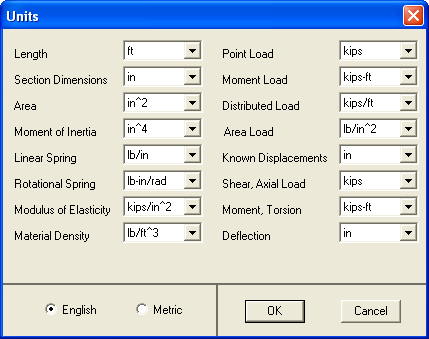
Figure 8-2 Define Units
Choose Define/Defaults and input 4080 for E, 145 for d, 900 for A, 67500 for Iz and Iy, 270000 for J, 0.25 for V, and 0 for a and B. Choose OK.
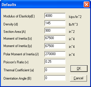
Figure 8-3 Define Defaults
Choose Define/Materials and input ConLW for label. Input 115 for d, 2600 for E, 0.25 for v, 0 for a, and choose ADD. The data are added to the list. Choose OK.
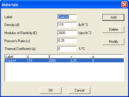
Figure 8-4 Define Materials
Choose Define/Sections and input 24x24 for LABEL. Select RECTANGULAR from the TYPE list, input 24 for width, 24 for depth, and choose ADD. The data are added to the list. Choose OK.
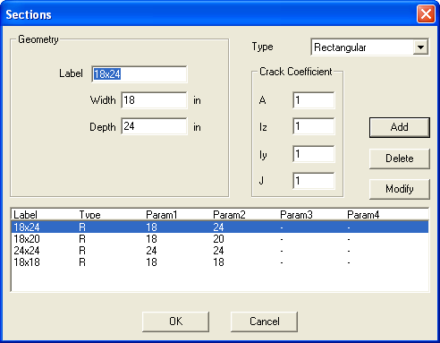
Figure 8-5 Define Sections
Choose Define/Member Loads and input the following entries. Choose ADD after each entry and OK when done
|
Label |
Type |
Orientation |
Dir |
W |
A |
b |
|
20K@.3 |
POINT |
GLOBAL |
Y |
-20 |
0.3 |
- |
|
15K@.3 |
POINT |
GLOBAL |
Y |
-15 |
0.3 |
- |
|
2.15U |
DISTRIBUTED |
GLOBAL |
Y |
-2.15 |
0 |
1 |
|
1.75U |
DISTRIBUTED |
GLOBAL |
Y |
-1.75 |
0 |
1 |
W = intensity, a = distance from J1/length, b = load length/length
Choose Define/Load Cases and input Dead, Live, and Wind in the label box, choosing ADD after each entry and OK when done.
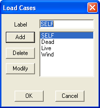
Figure 8-6 Define Load Cases
Choose Define/Load Combinations. In the LABEL box enter 1.4D+1.7L. Select SELF and DEAD from the LOAD CASE list, input 1.4 in the FACTOR box, and choose INCLUDE. Select LIVE from the LOAD CASE list, input 1.7 in the FACTOR box, and choose INCLUDE. Choose ADD. The combination is added to the list at the bottom.
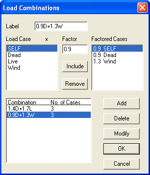
Figure 8-7 Define Load Combinations
In the LABEL box, enter 0.9D+1.3W. Select all items in the FACTORED CASES box and choose REMOVE. Select SELF and DEAD from the LOAD CASE list, input 0.9 in the FACTOR box, and choose INCLUDE. Select WIND from the LOAD CASE list, input 1.3 in the FACTOR box, and choose INCLUDE. Choose ADD. The combination is added to the list at the bottom. Choose OK.