2.1. Introduction
spMats uses the Finite Element Method for the structural modeling and analysis of reinforced concrete slab systems or mat foundations subject to static loading conditions.
The slab is idealized as a mesh of rectangular elements interconnected at the corner nodes. The same mesh applies to the underlying soil with the soil stiffness concentrated at the nodes. Slabs of irregular geometry will be idealized to conform to geometry with rectangular boundaries. Even though slab and soil properties can vary between elements, they are assumed uniform within each element.
The three degrees of freedom are considered at each node are the vertical translation and two rotations about the two orthogonal axes. An external load can exist in the direction of each of the above degrees of freedom, i.e., a vertical force and two moments about the Cartesian axes.
2.1.1. Foundation Slab Mat Systems
spMats can be used to model, analyze, and design foundation systems such as mat foundations, spread and combined footings, soil-supported foundations, slabs on grade, pile-supported foundations. Samples of such systems are illustrated below:
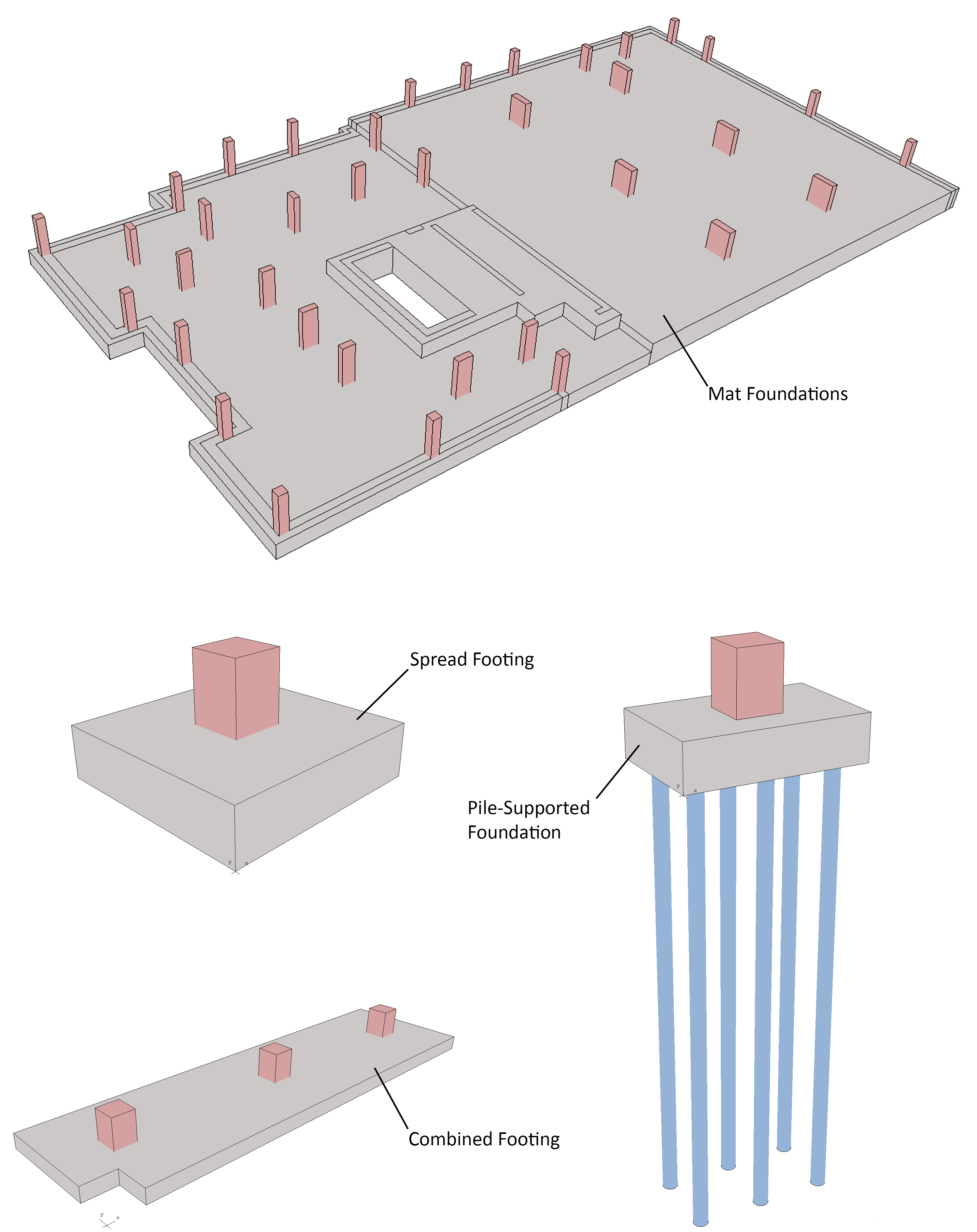
Figure 2.1 - Foundation Systems
Global Coordinate System
The mid-surface of the slab lies in the XY plane of the right-handed XYZ orthogonal coordinate system shown in Figure 2.2. The slab thickness is measured in the direction of the Z-axis. Looking at the display monitor, the origin of the global coordinate system is located in the bottom left corner of the screen. The positive X-axis points to the right, the positive Y-axis points upward towards the top of the monitor, and the positive Z-axis points out of the screen. Thus, the XY plane is defined as being the plane of the display monitor.
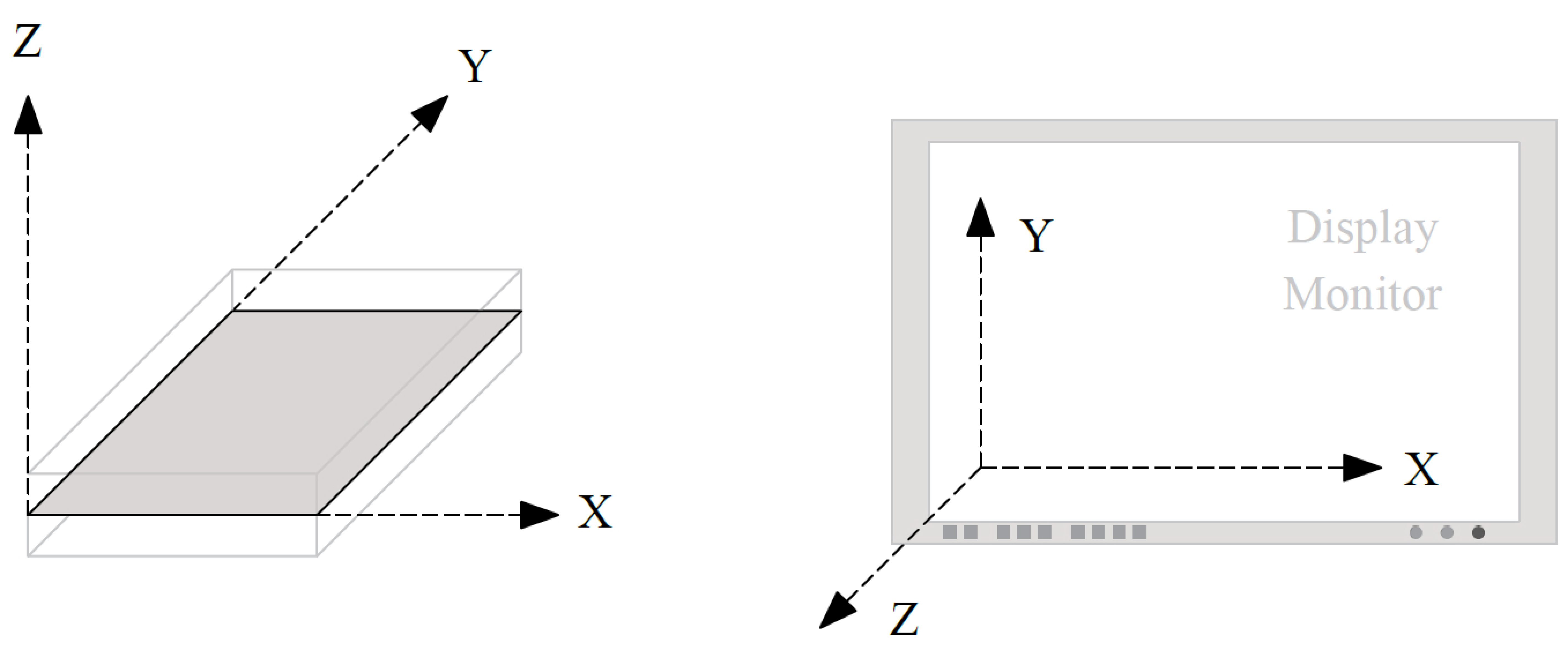
Figure 2.2 - Global Coordinate System
There is no local coordinate system requirement in spMats.