In this chapter several examples are presented to demonstrate capabilities of the program. Generally program results match closely the results found in the referenced text books. When discrepancies are observed, they result from variations in assumptions and solutions methods, and numerical accuracy.
Both beams/one-way slab systems as well as two-way slab systems are presented in the examples. The output of beams/one-way slab examples shows that spBeam program was used to solve them. This is to illustrate that spBeam program is available as a limited version of spSlab including only beams/one-way slab capabilities.
8.1. Example 1 - Spandrel Beam with Moment Redistribution
Determine the required reinforcement for the spandrel beam at an intermediate floor level as shown below, using moment redistribution to reduce total reinforcement required. (Note: the self-weight is already included in the specified dead load below.)1
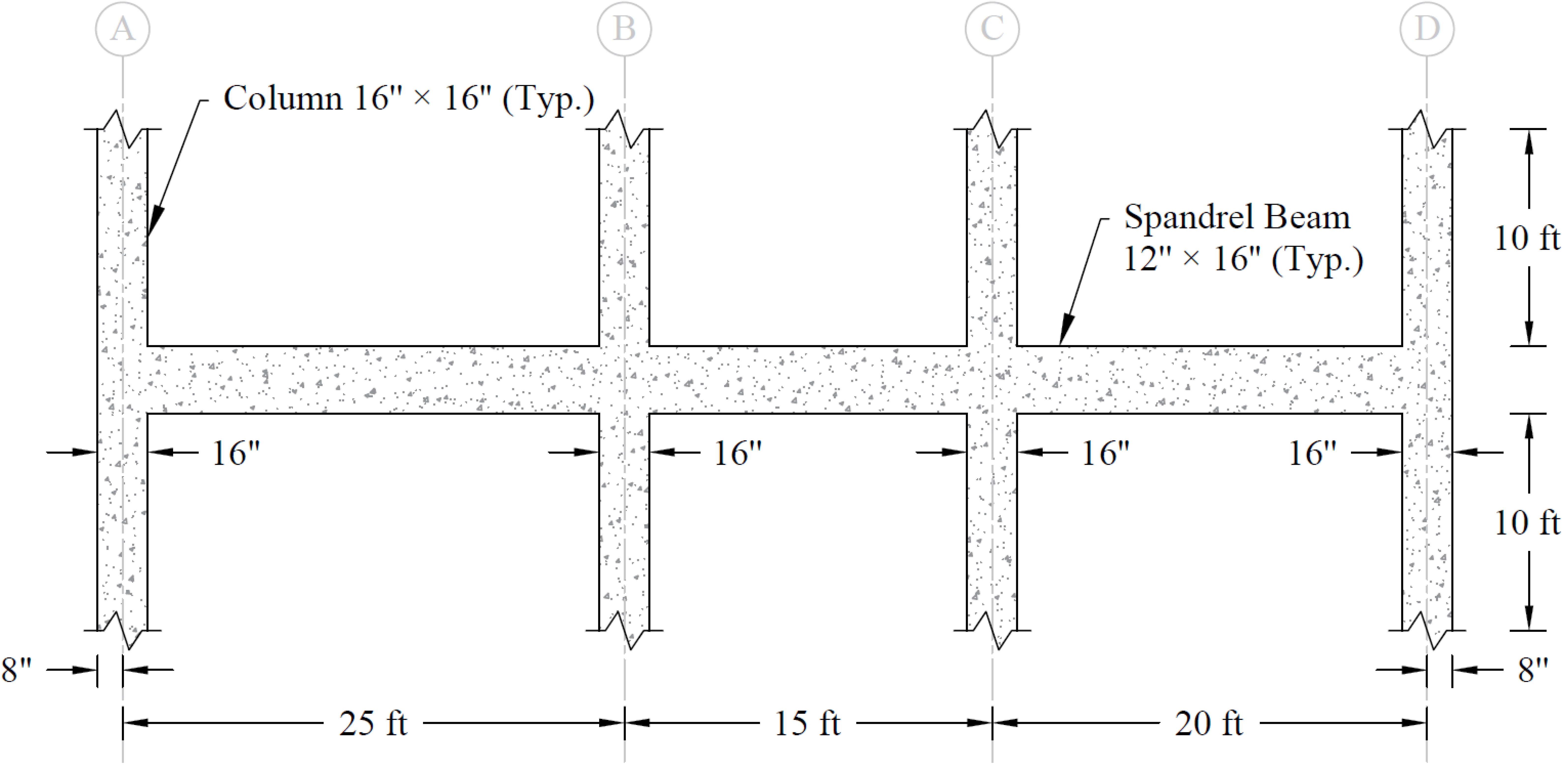
Figure 8.1 - Example Spandrel Beam Problem
Design data
DL | = | 1,167 lb/ft | |
LL | = | 450 lb/ft | |
fc’ | = | 4,000 psi | |
fy | = | 60,000 psi | |
Columns: | 16 × 16 in. | ||
Story height: | 10 ft | ||
Spandrel beam: | 12 × 16 in. | ||
1. From the Start screen, select New Project.
2. From the Main Program Window, select Project from the Ribbon.
• In the General section, select the DESIGN CODE, UNIT SYSTEM, and BAR SET.
• In the Materials section, input the following:
f'c (SLABS & BEAMS): | 4.00 ksi |
f'c (COLUMNS): | 4.00 ksi |
fy: | 60.00 ksi |
Alternatively, detailed material properties for Concrete and Reinforcement Steel can be entered using Definitions dialog box (see Steps 4 and 5).
• In the Run Options section, select the following:
RUN MODE: | Design |
FLOOR SYSTEM: | One-Way/Beam |
CONSIDER TORSION: | No |
• In the Description section, enter the PROJECT, FRAME, and ENGINEER.
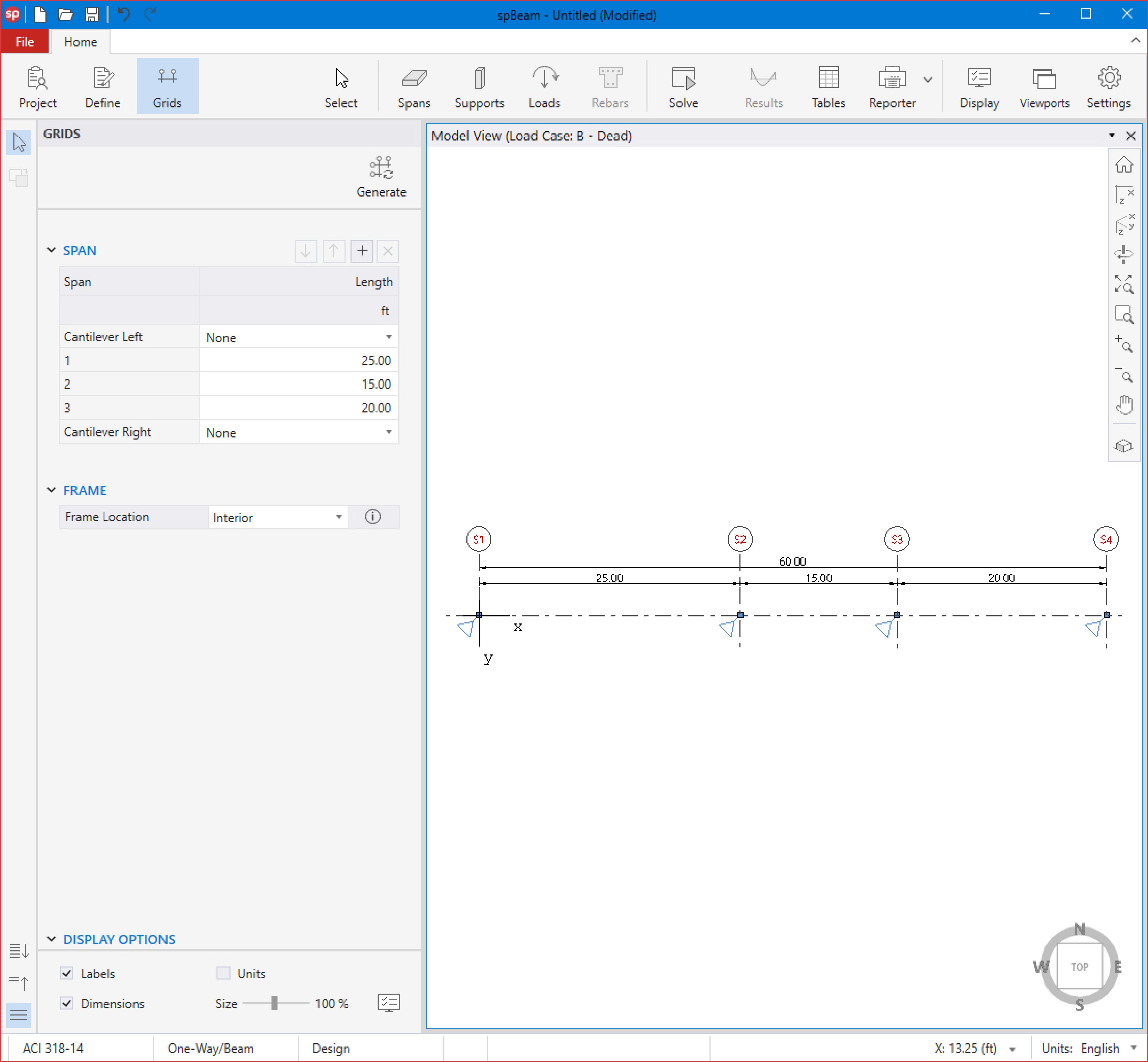
3. From the Ribbon, select Grids.
• Click on the Generate in the left panel to have the program surface the following:
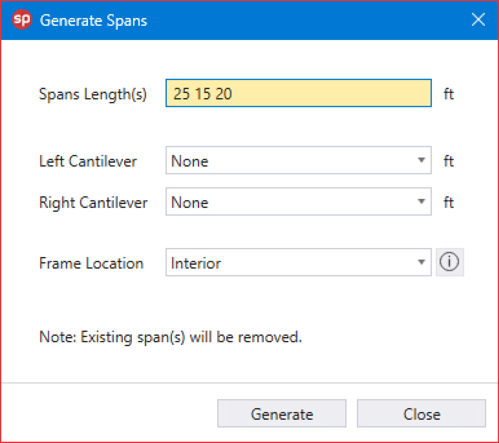
• Enter the following values in the corresponding text boxes:
SPANS LENGTH(S): | 25 15 20 |
LEFT CANTILEVER: | None |
RIGHT CANTILEVER: | None |
FRAME LOCATION: | Interior |
• Click on the GENERATE button to return to the main window. Notice how the grid lines now appear in the VIEWPORT.
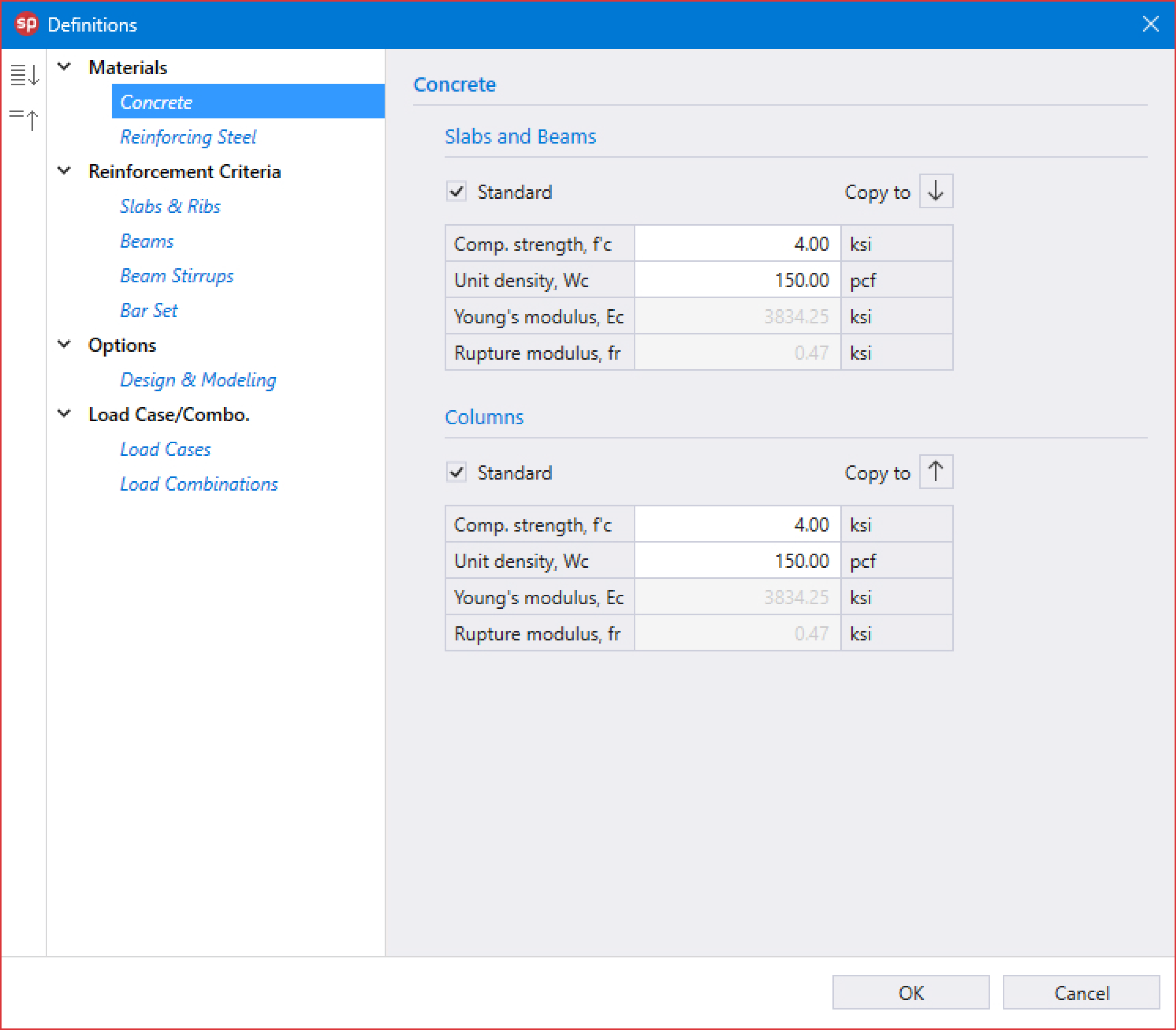
4. From the Ribbon, select Define, then choose Concrete from Materials to display the Concrete dialog box.
• Check STANDARD for SLABS AND BEAMS and COLUMNS.
• Enter the following for SLABS AND BEAMS and COLUMNS:
COMPRESSIVE STRENGTH, f'c: | 4.00 ksi |
UNIT DENSITY, Wc: | 150.00 pcf |
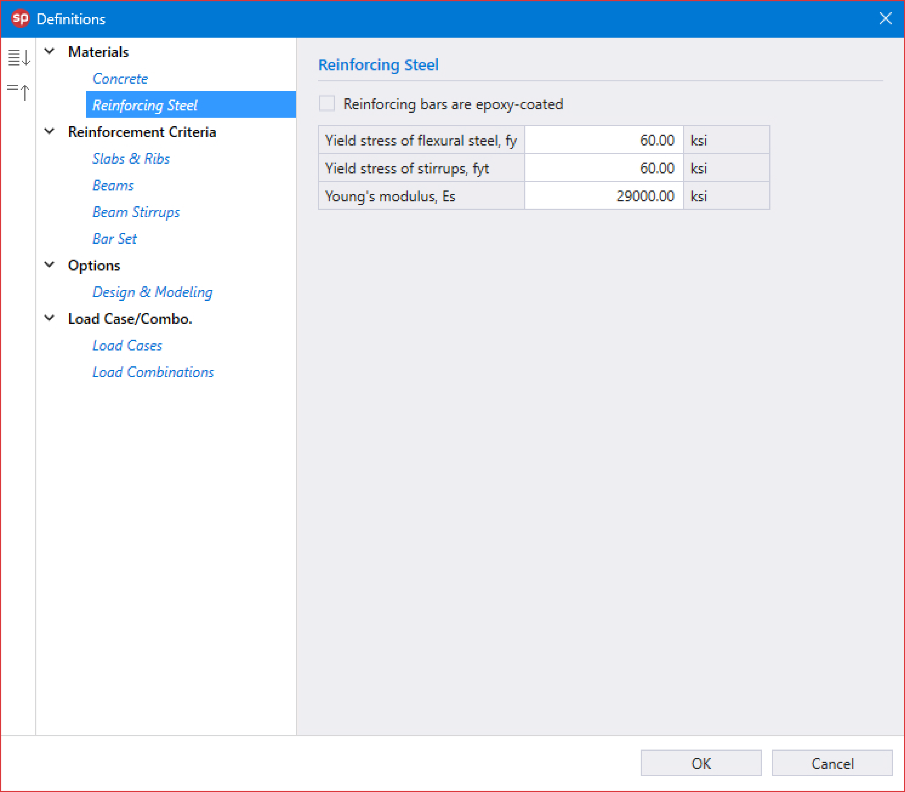
5. Click on Reinforcing Steel from Materials to display the Reinforcing Steel dialog box.
YIELD STRESS OF FLEXURAL STEEL, fy: | 60.00 ksi |
YIELD STRESS OF STIRRUP, fyt: | 60.00 ksi |
YOUNG’S MODULUS, Es: | 29000.00 ksi |
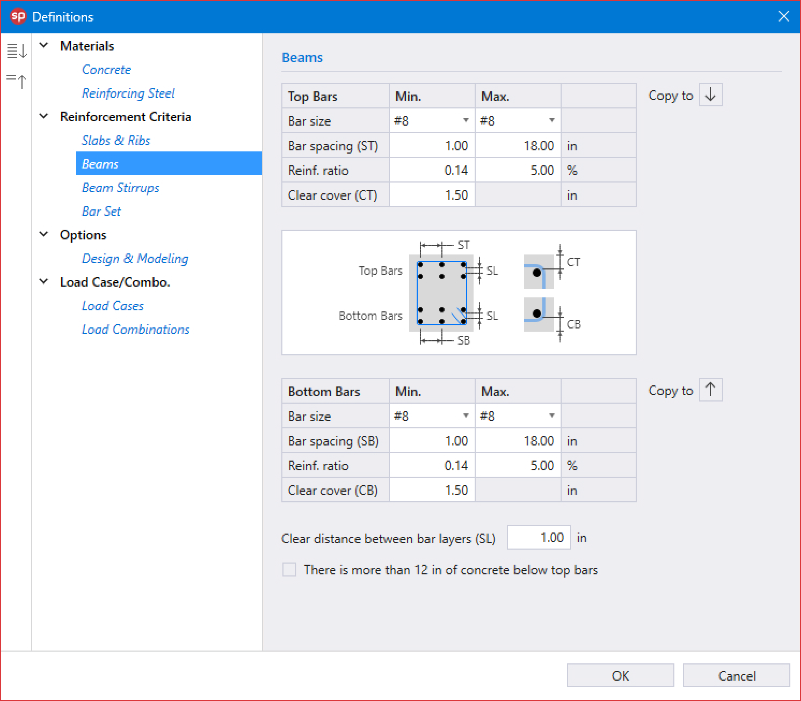
6. Click on Beams from Reinforcement Criteria to display the Beams dialog box.
• Enter the following for TOP BARS and BOTTOM BARS:
Min. | Max. | |
BAR SIZE: | #8 | #8 |
BAR SPACING (ST): | 1.00 in | 18.00 in |
REINFORCEMENT RATIO: | 0.14 % | 5.00 % |
CLEAR COVER (CT): | 1.50 in | |
CLEAR DISTANCE BETWEEN BAR LAYERS (SL): | 1.00 in | |
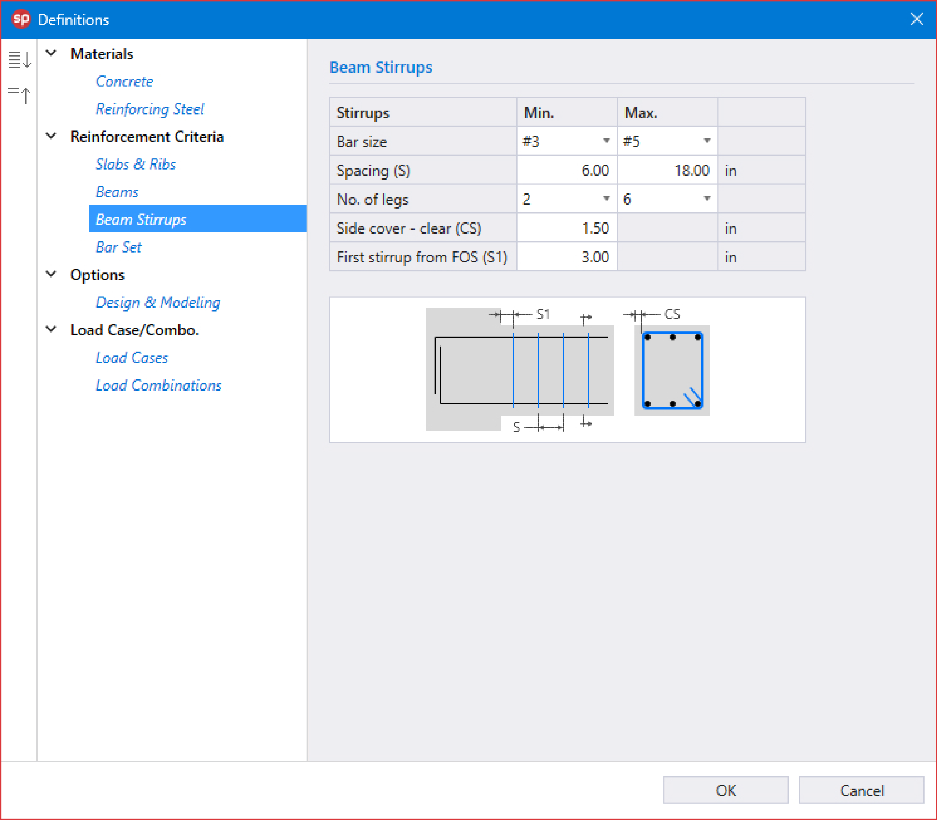
7. Click on Beam Stirrups from Reinforcement Criteria to display the Beam Stirrups dialog box.
• Enter the following:
Min. | Max. | |
BAR SIZE: | #3 | #5 |
BAR SPACING (S): | 6.00 in | 18.00 in |
NUMBER OF LEGS: | 2 | 6 |
SIDE COVER - CLEAR (CS): | 1.50 in | |
FIRST STIRRUP FROM FOS (S1): | 3.00 in | |
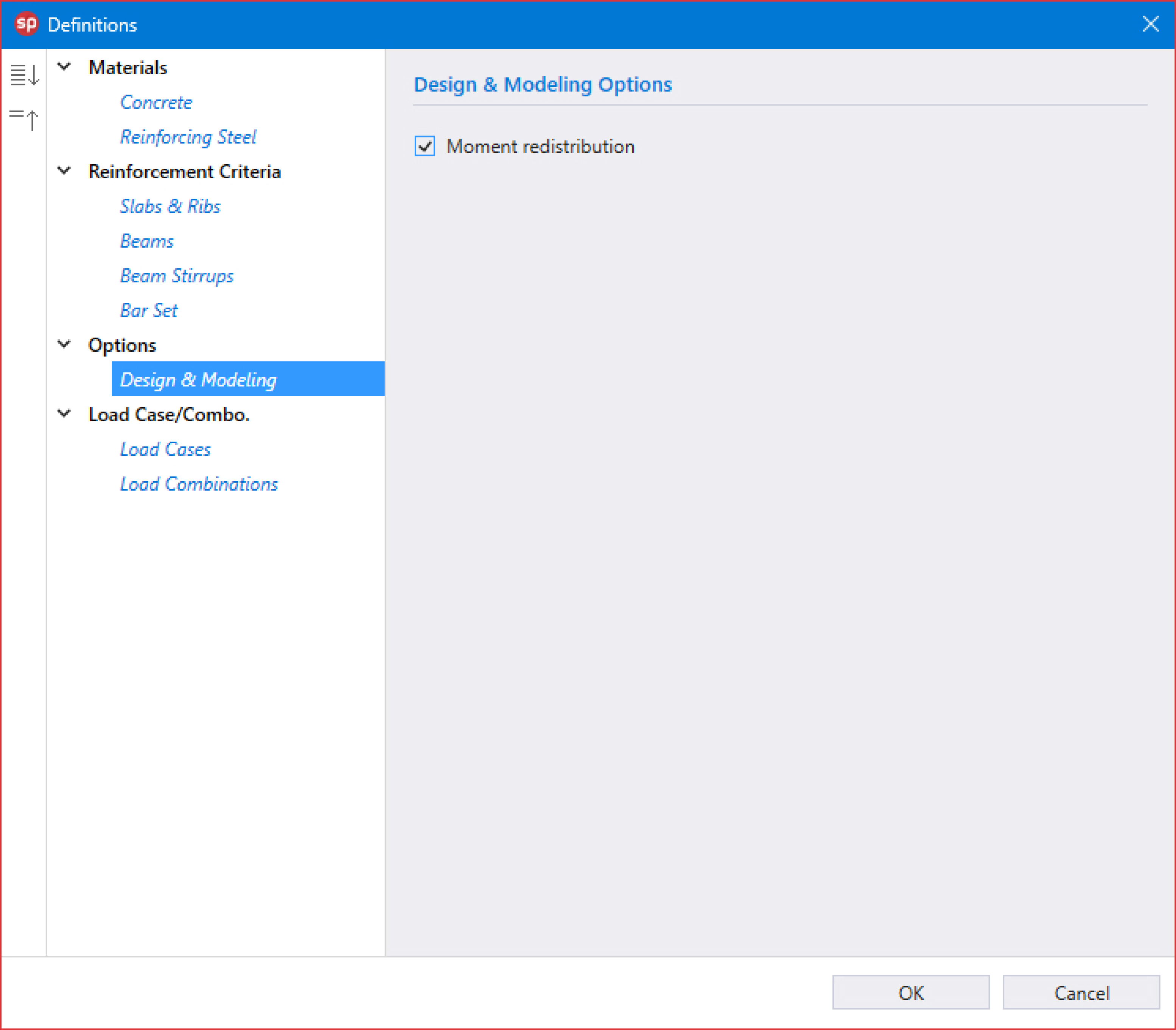
8. Click on Design & Modeling from Options to display the Design & Modeling dialog box.
• Check MOMENT REDISTRIBUTION.
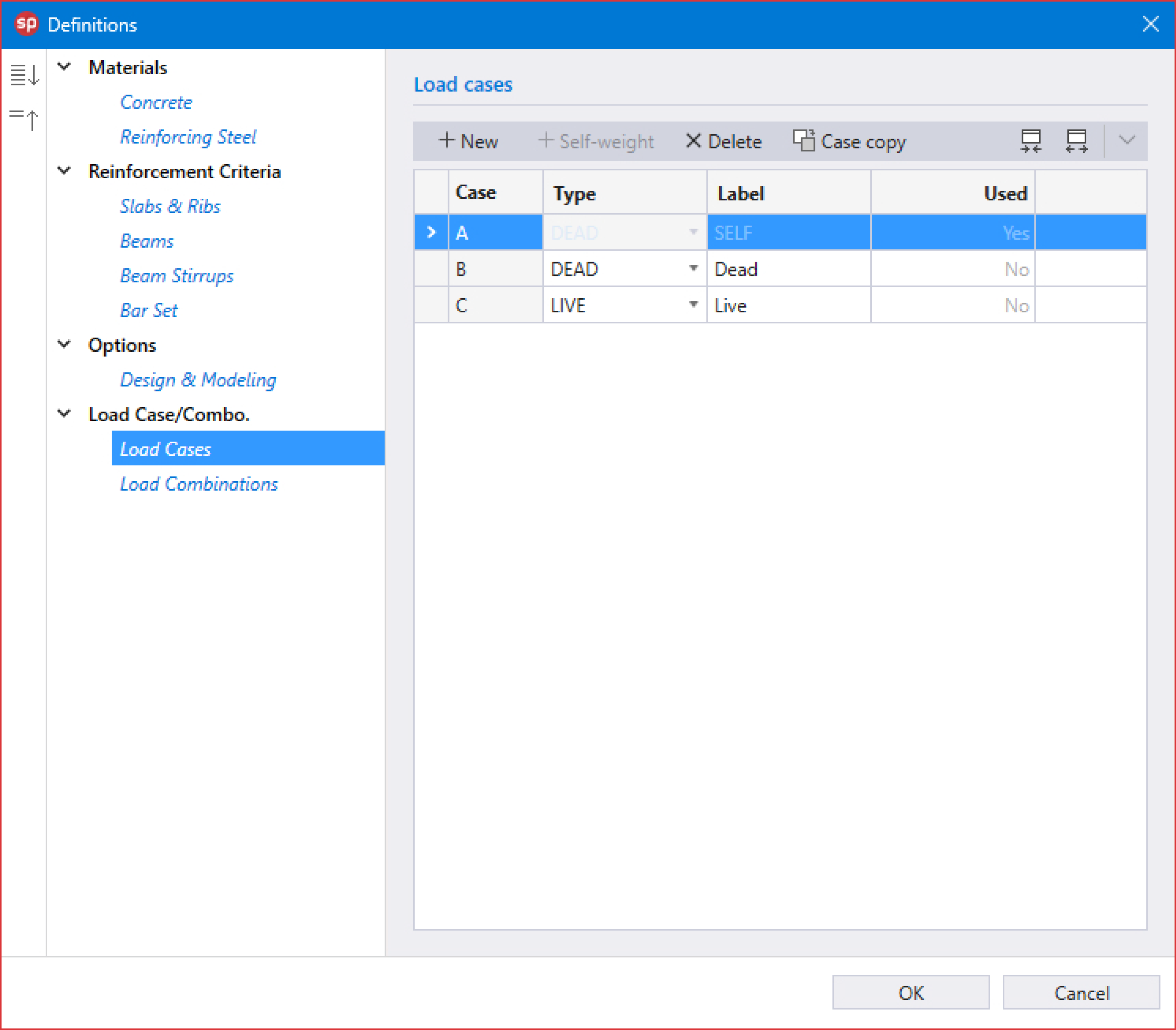
9. Click on Loads Cases from Load Case/Combo. to display the Load Cases dialog box.
• Add SELF-WEIGHT for CASE A.
• Enter the following:
CASE B: | Dead |
CASE C: | Live |
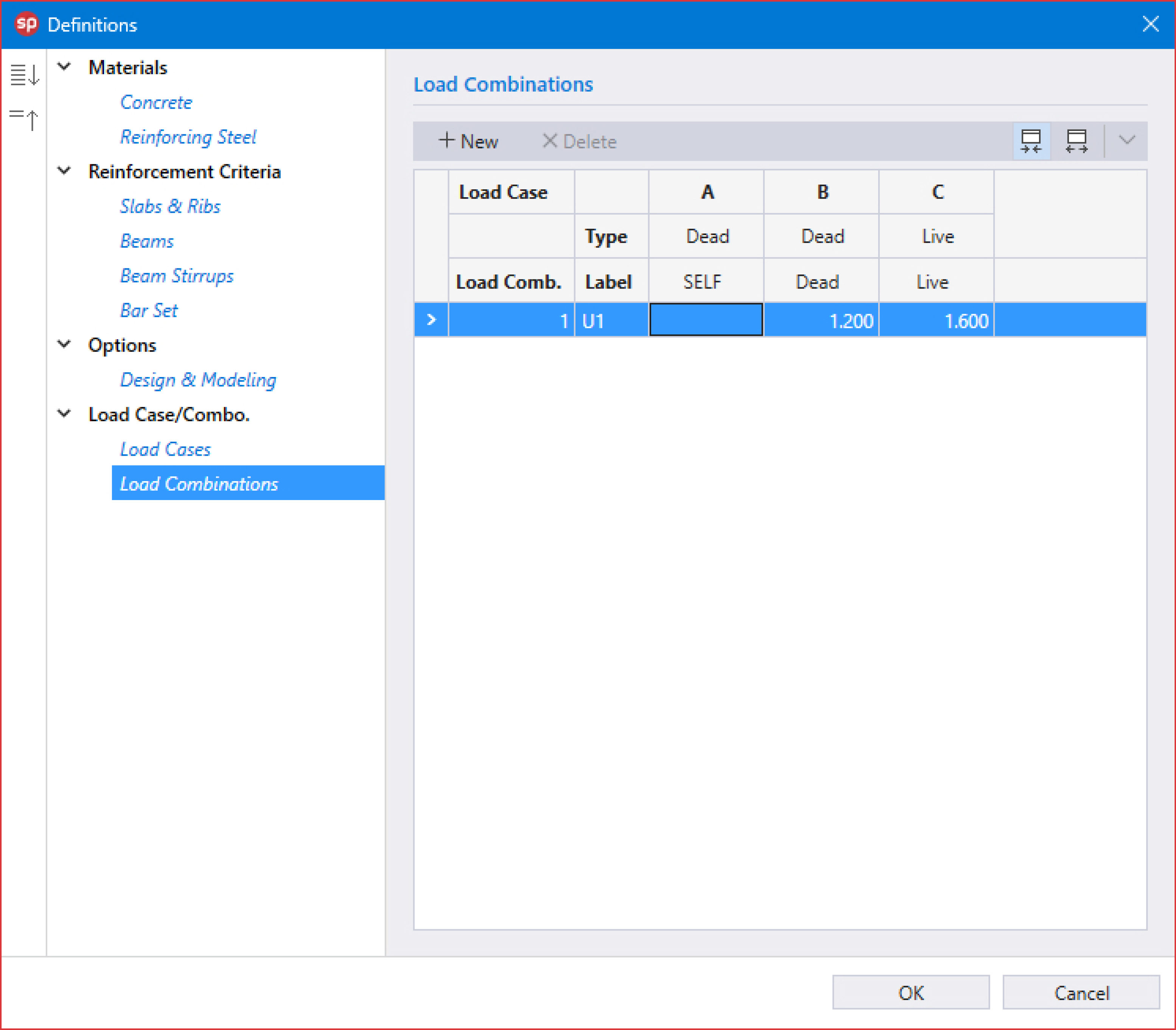
10. Click on Load Combinations from Load Case/Combo. to display the Load Combinations dialog box.
• Enter the following load combination shown in the figure below:
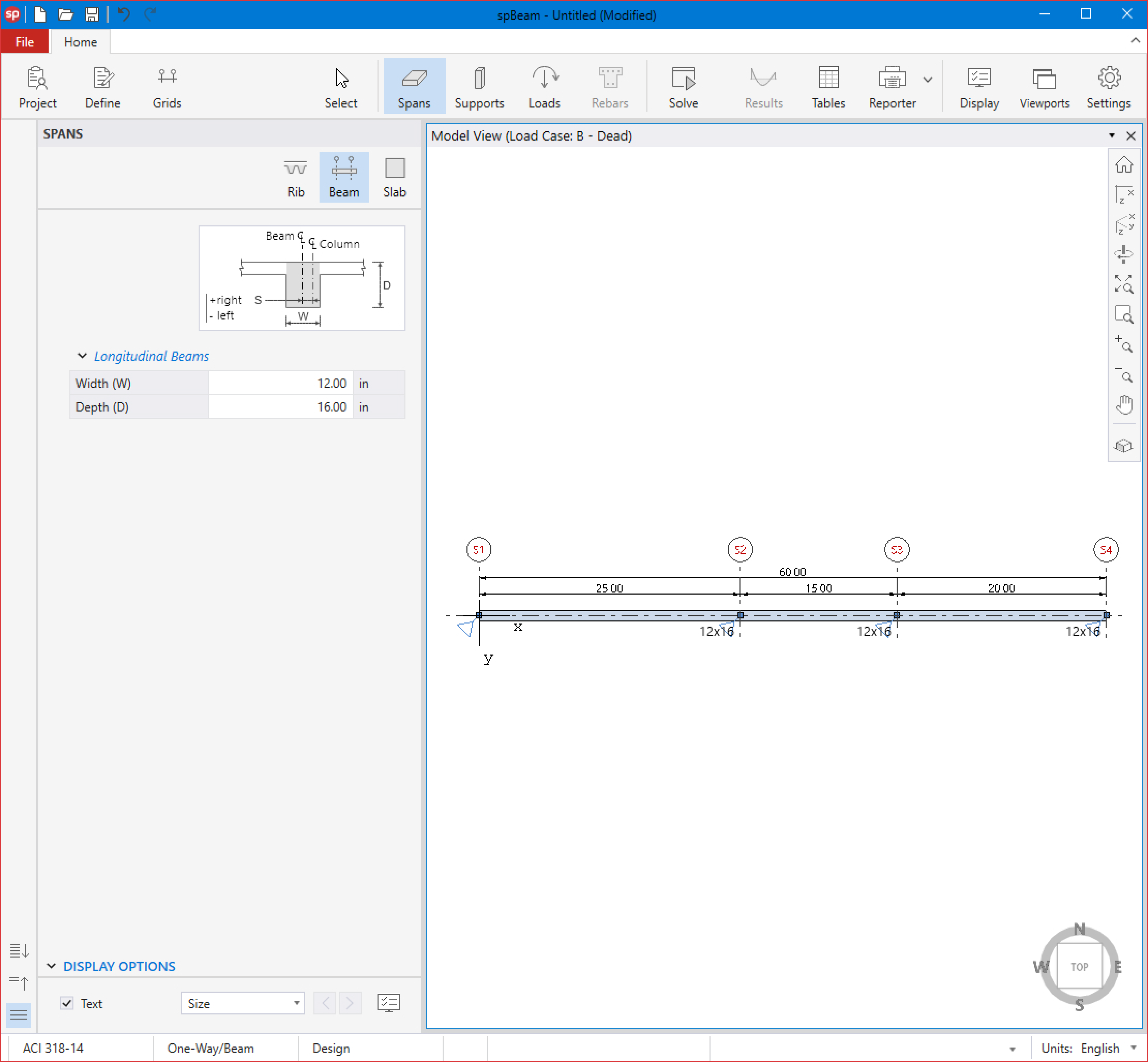
11. From the Ribbon, select Spans command.
• In the left panel, select Beam and enter the following:
WIDTH (W): | 12.00 in |
DEPTH (D): | 16.00 in |
• Apply to all spans as shown in the figure below.
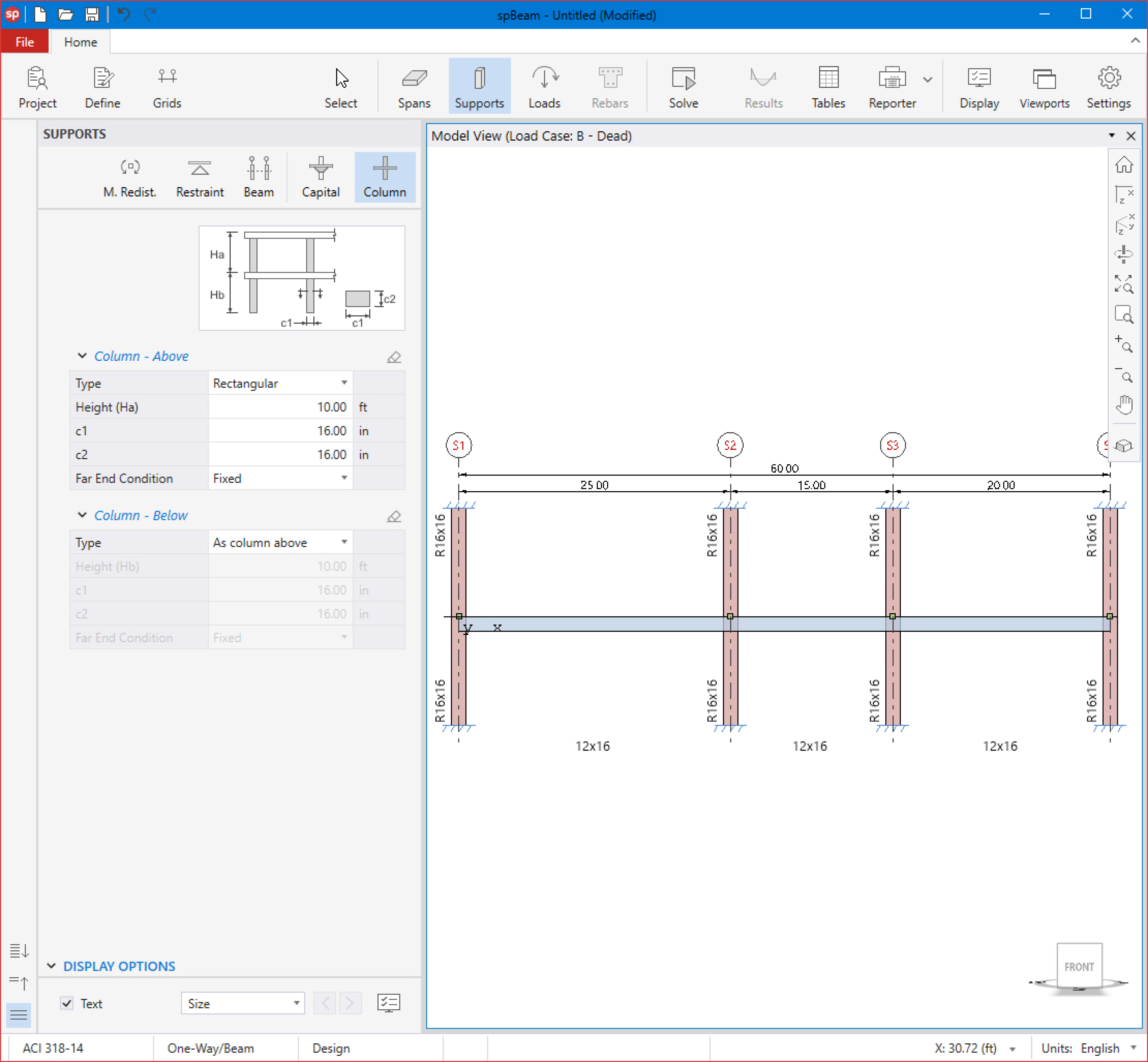
12. From the Ribbon, select Supports command.
• In the left panel, select Column and enter the following for COLUMN - ABOVE and COLUMN - BELOW:
TYPE: | Rectangular |
HEIGHT: | 10.00 ft |
c1: | 16.00 in |
c2: | 16.00 in |
FAR END CONDITION: | Fixed |
• Apply to all supports as shown in the figure below.
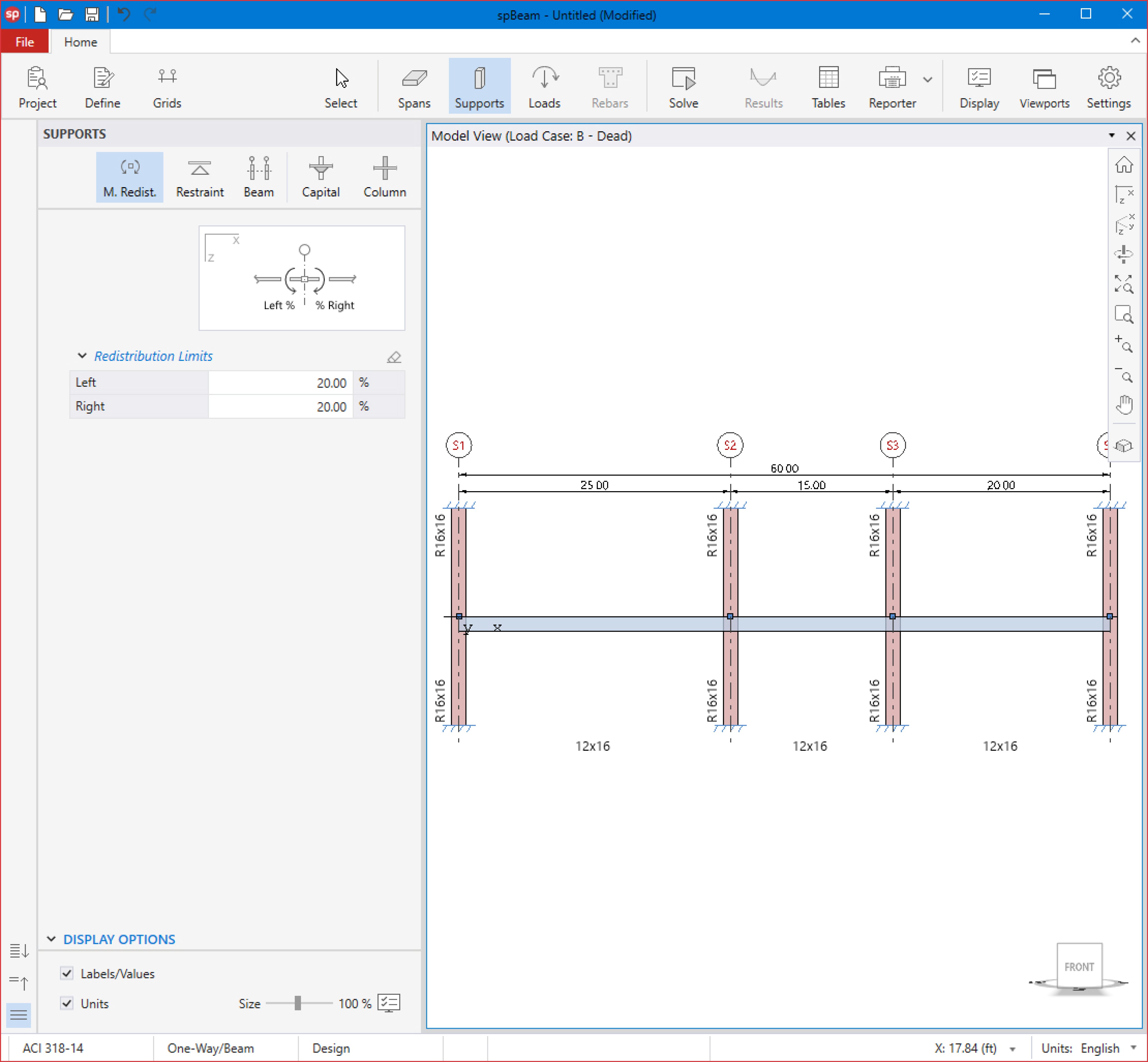
• In the left panel, select Moment Redistribution and enter the following:
LEFT: | 20.00 % |
RIGHT: | 20.00 % |
• Apply to Support 2 and Support 3 as shown in the figure below.
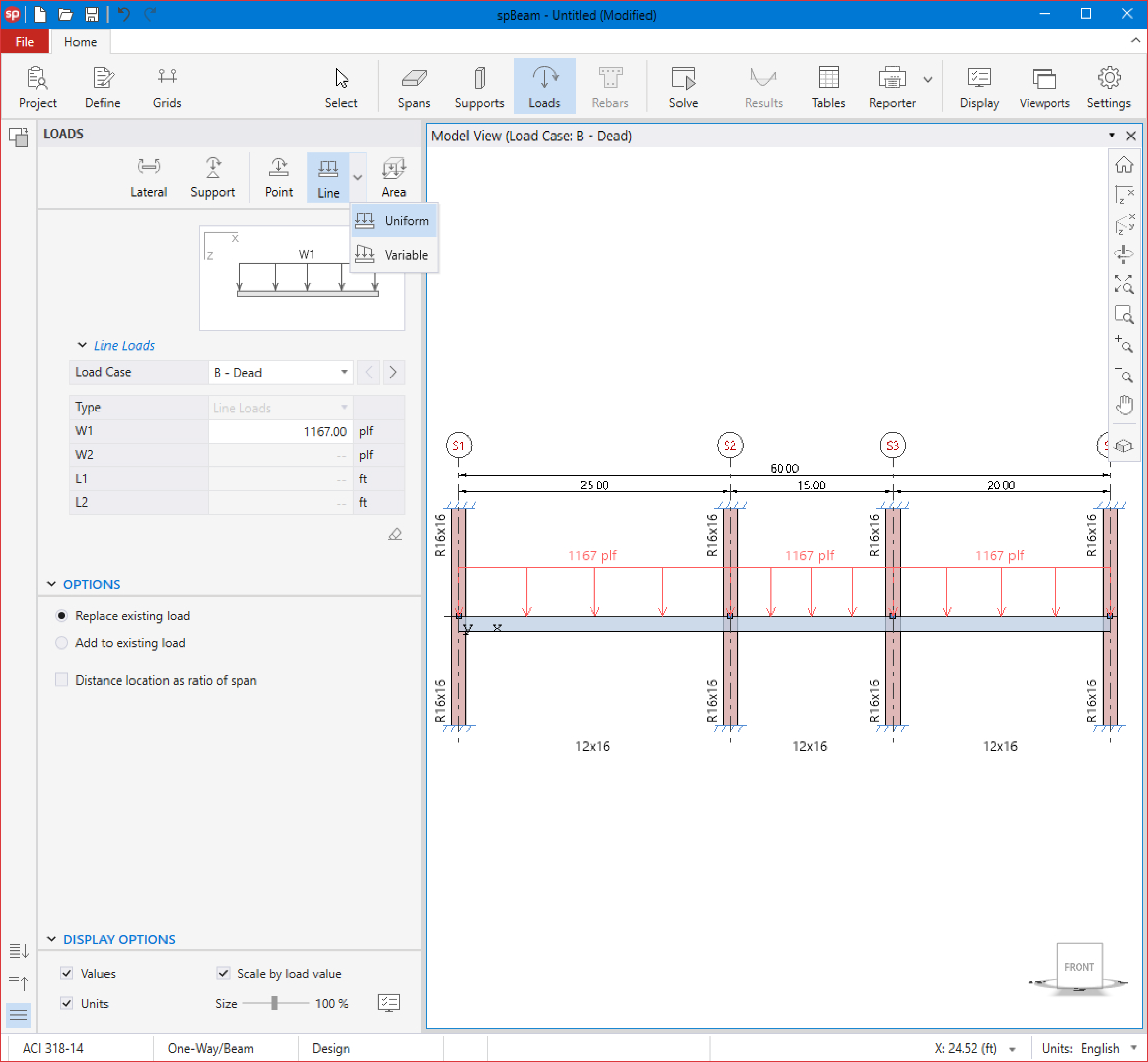
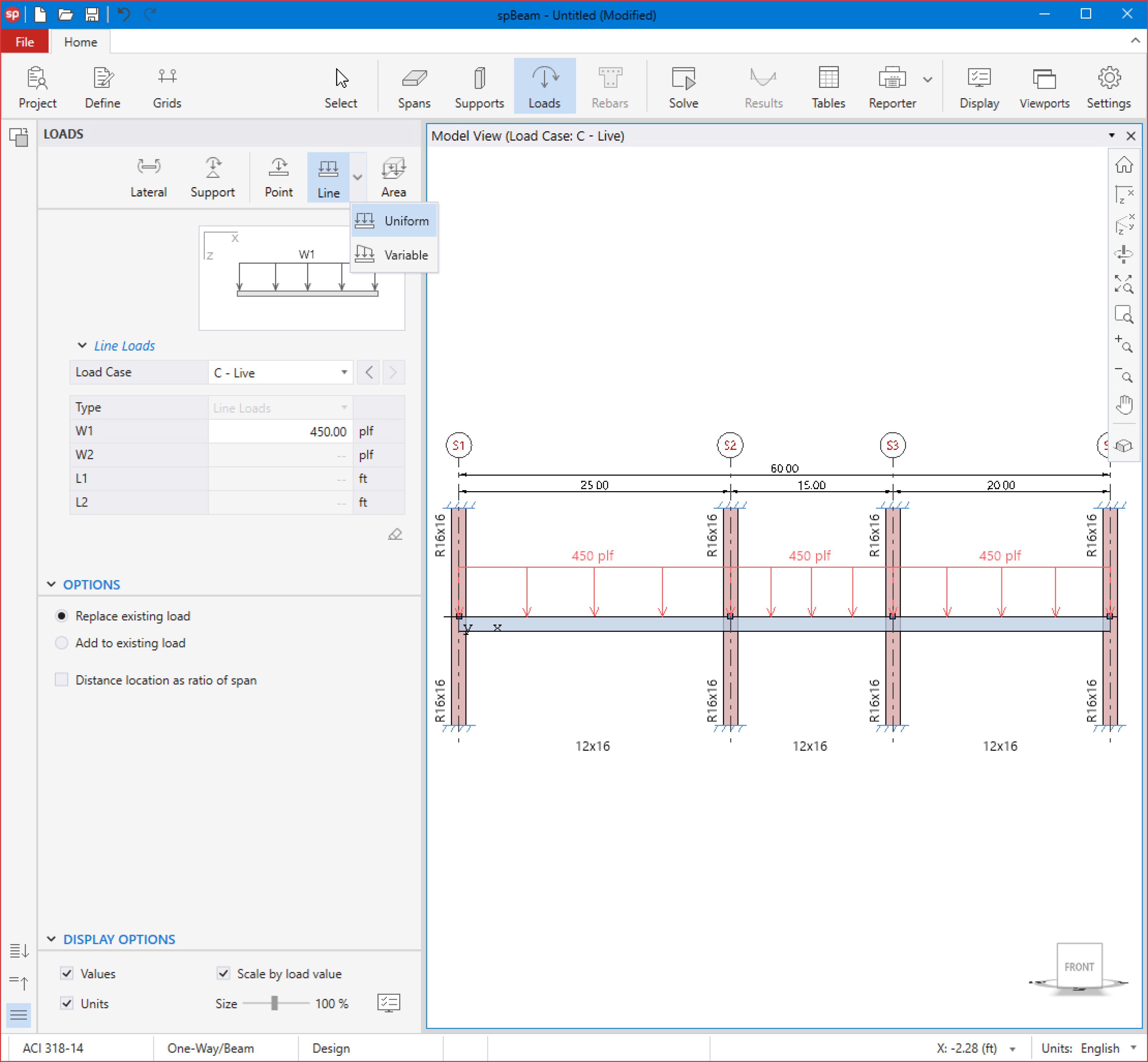
13. From the Ribbon, select Loads command.
• In the left panel, select Uniform Line Loads then select B-DEAD from LOAD CASE and enter the following:
W1: | 1167.00 plf |
• Apply to all spans as shown in the figure below.
• Select C-LIVE from LOAD CASE and enter the following:
W1: | 450.00 plf |
• Apply to all spans as shown in the figure below.
14. From the Ribbon, select Solve command.
For Design Options:
• Leave all Design Options to their default settings.
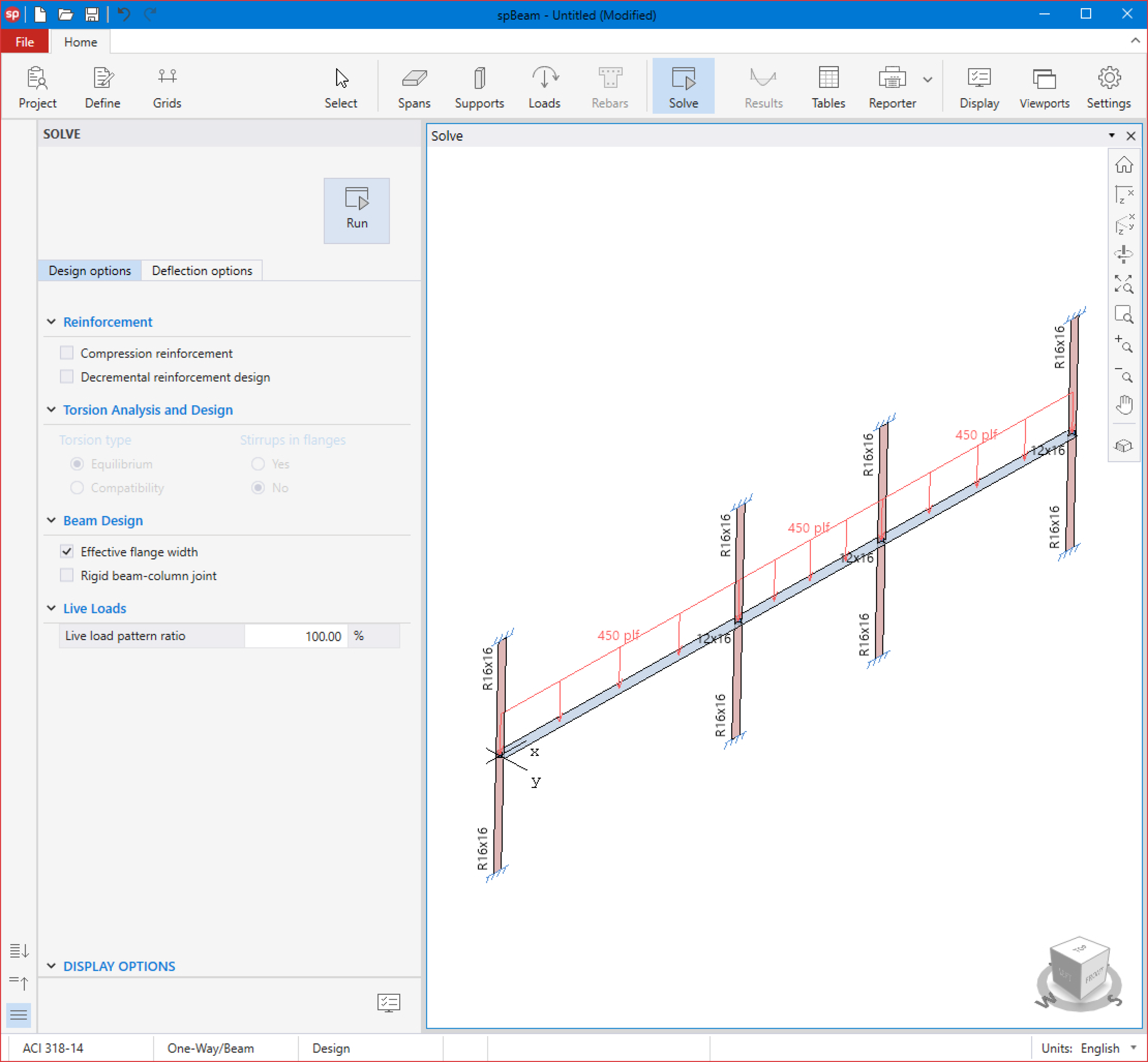
For Deflection Options:
• Leave all Design Options to their default settings.
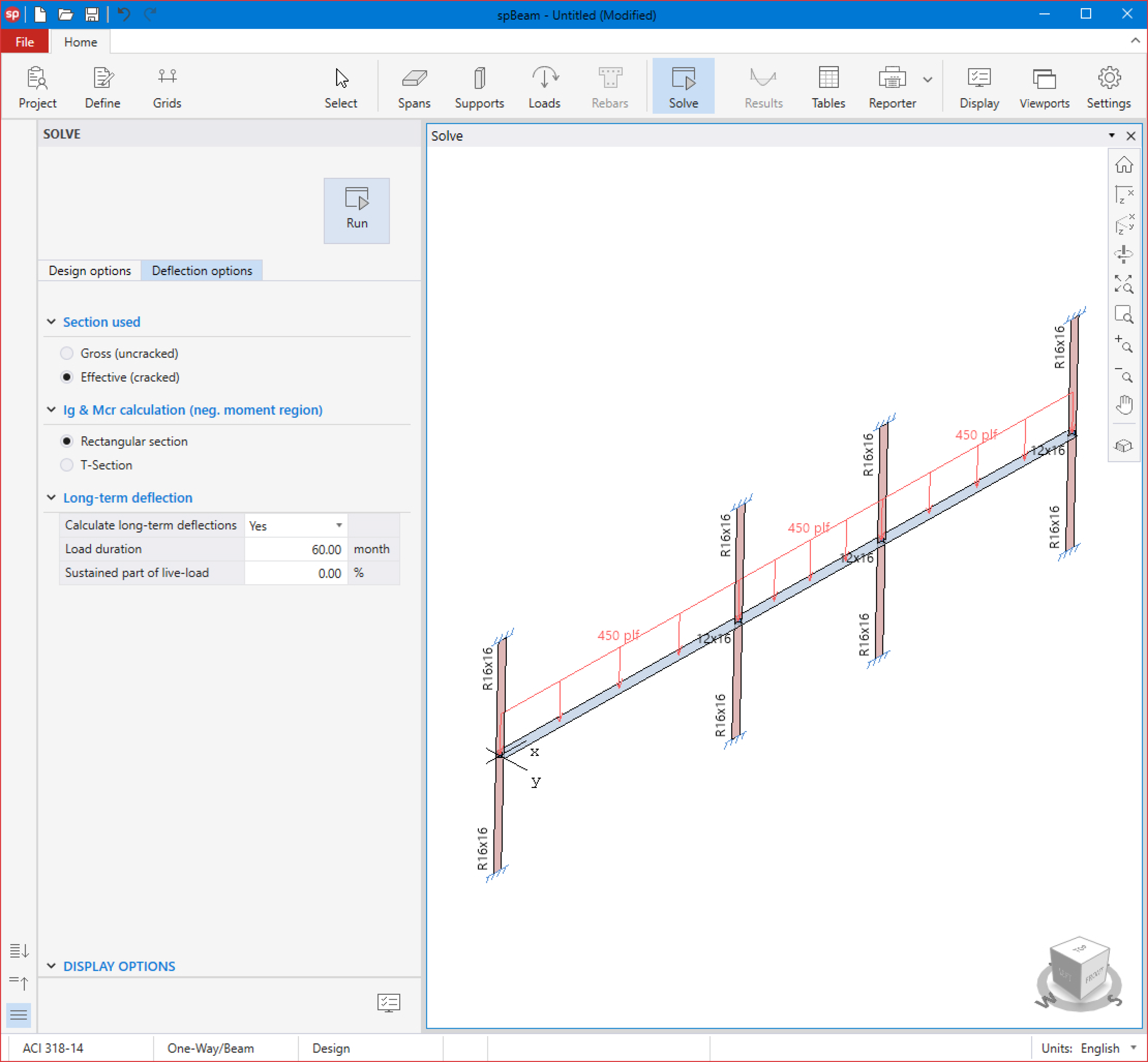
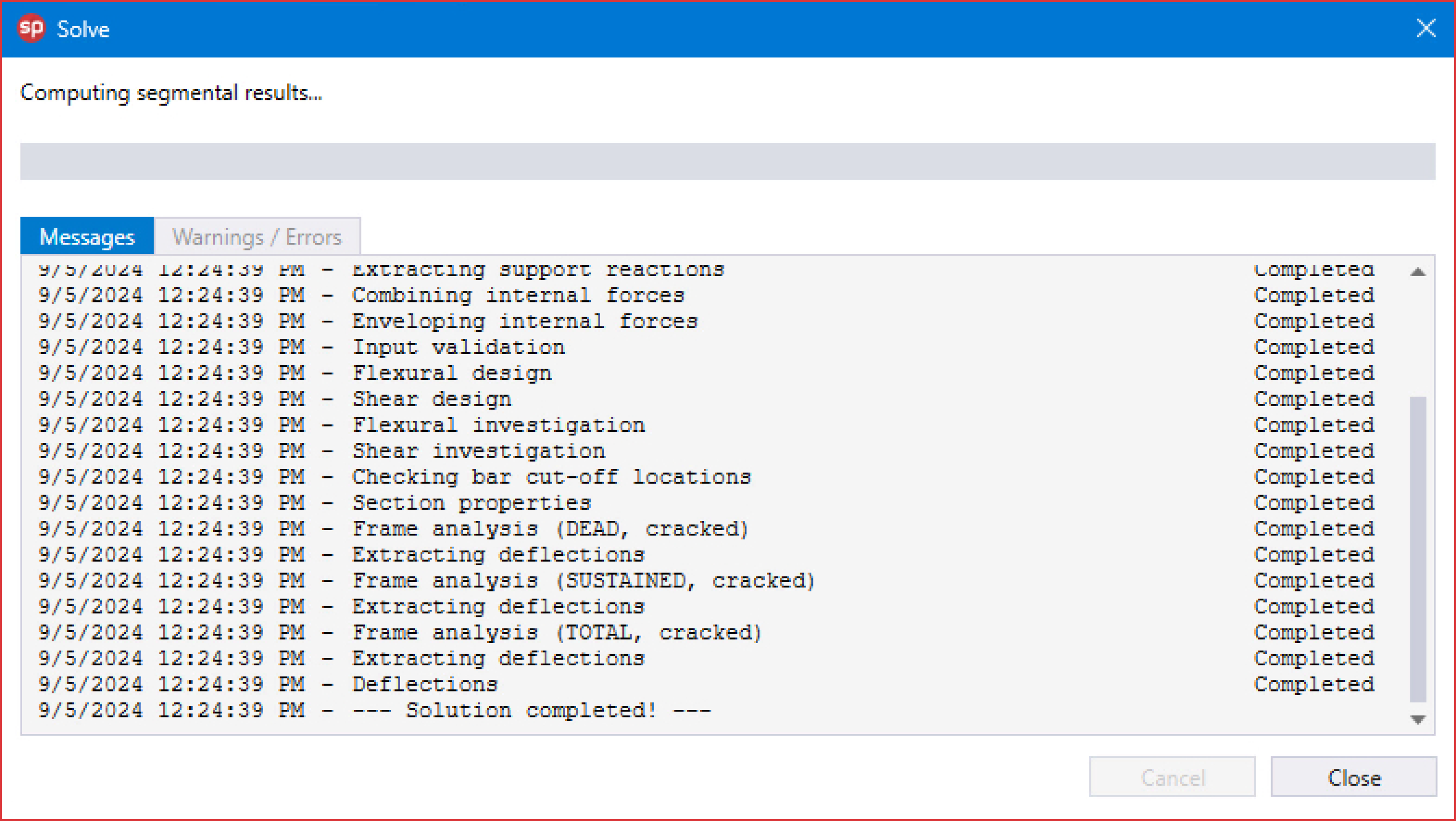
• Click on the Run button.
• The spBeam Solver window is displayed and the solver messages are listed. After the solution is done, the design will be performed and then the focus will immediately be passed to the Results scope.
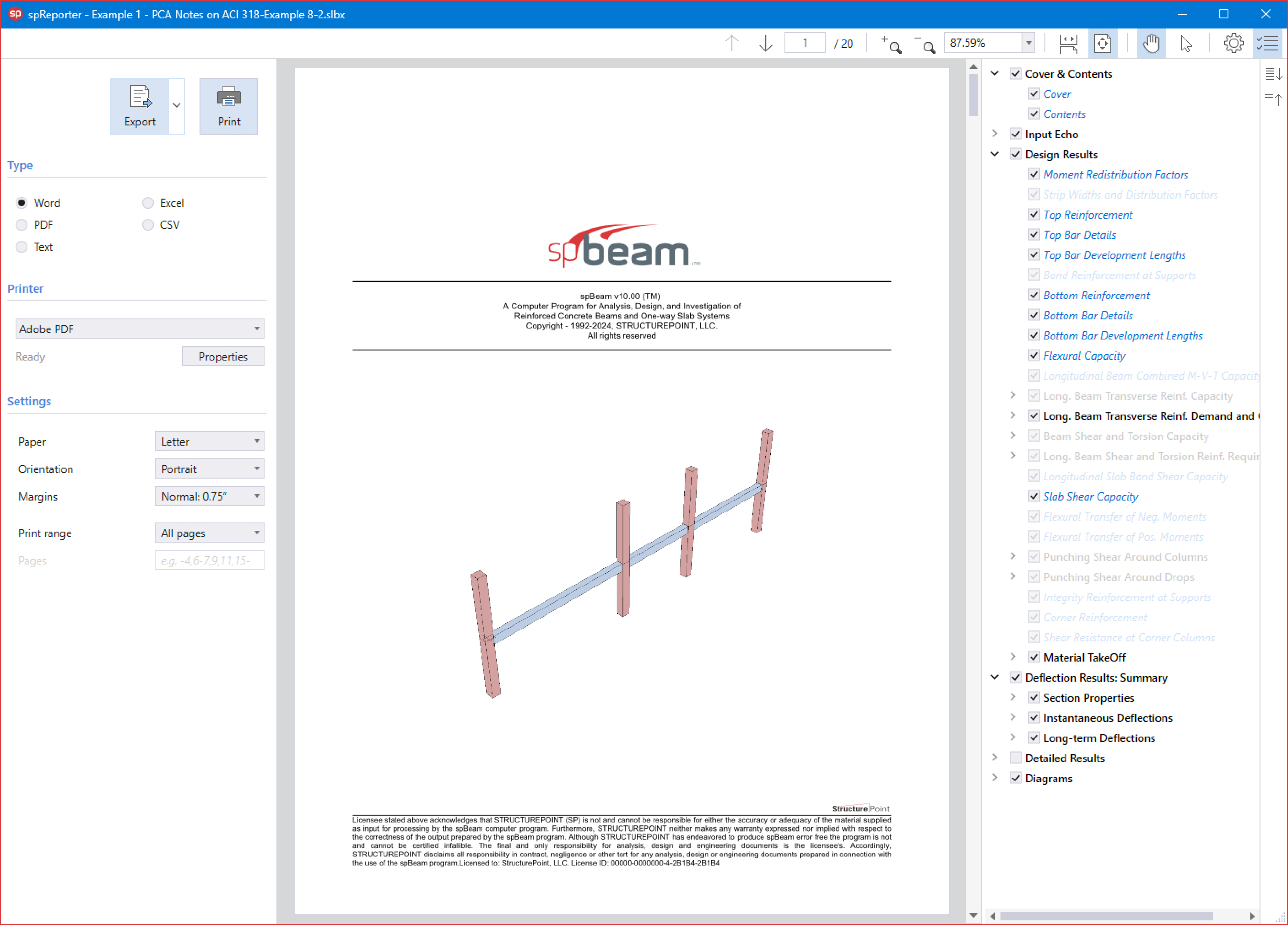
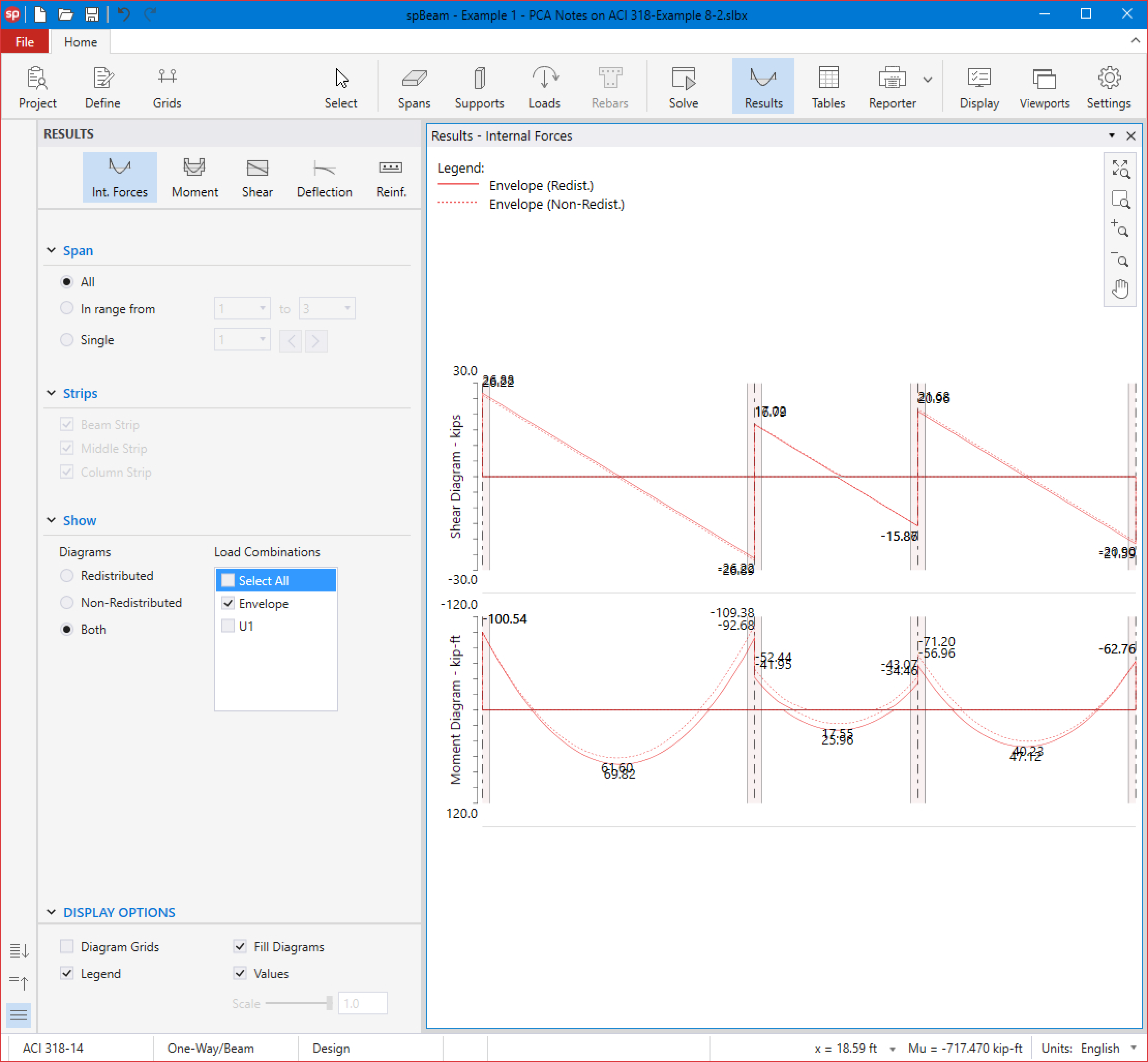
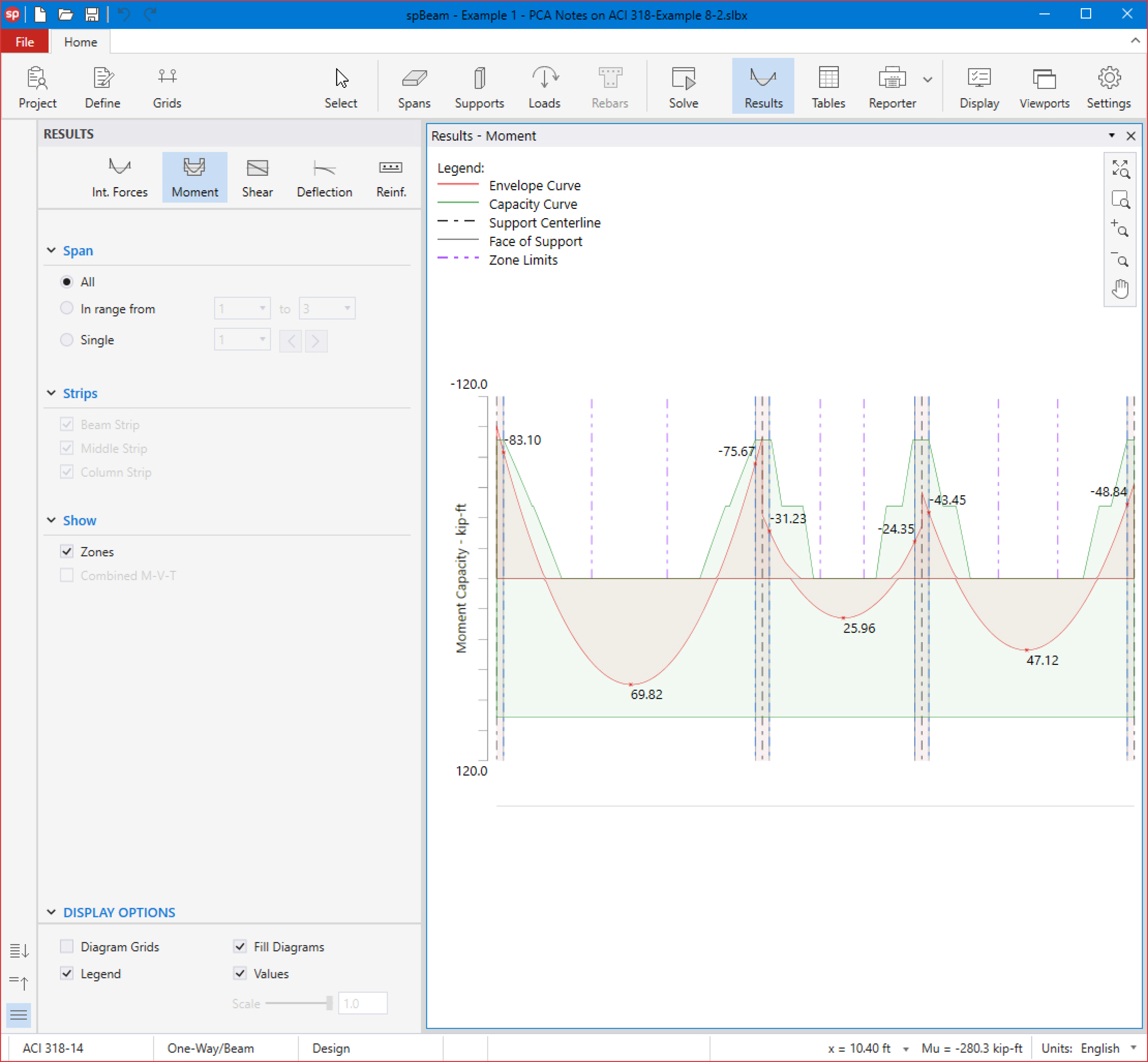
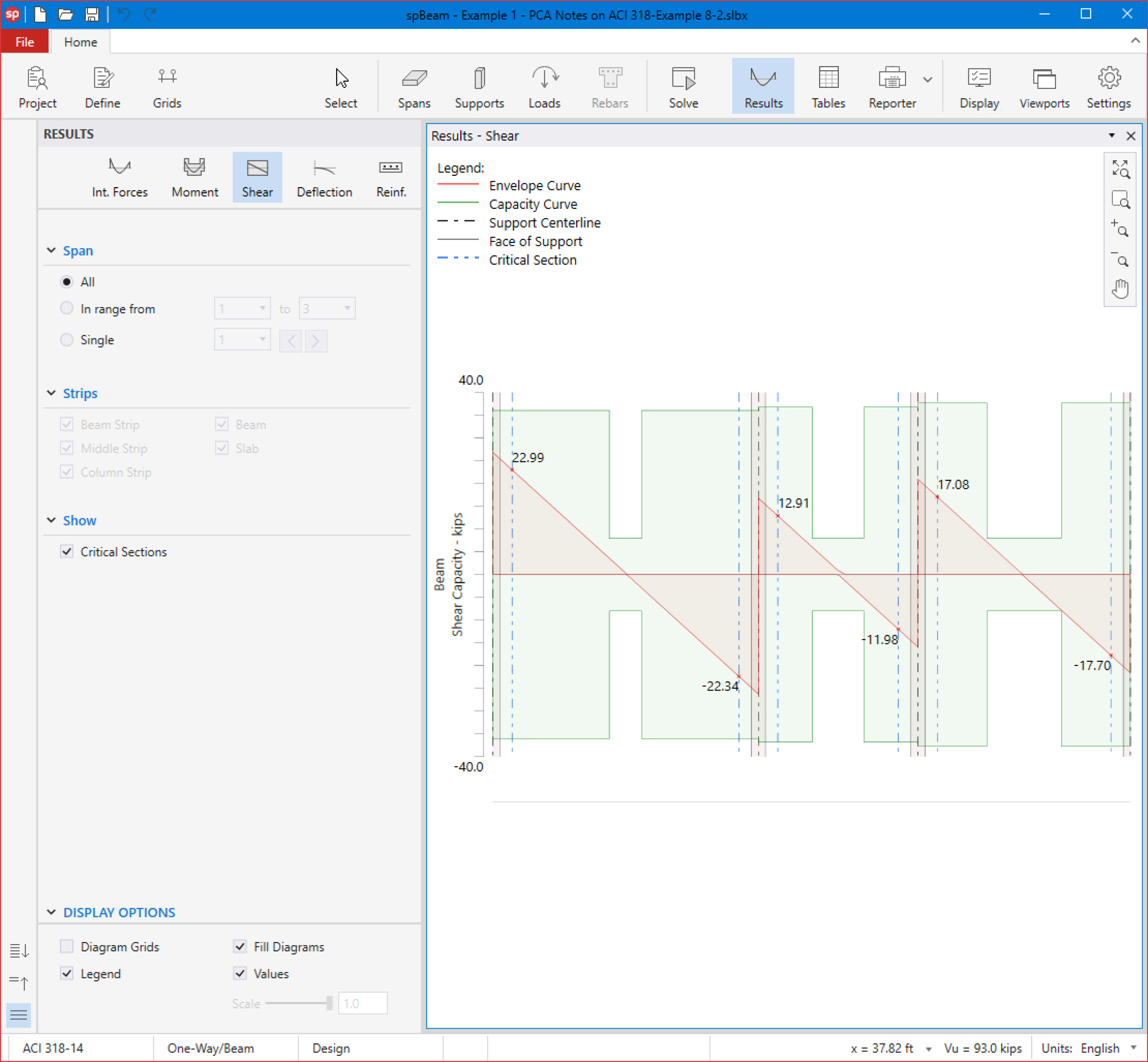
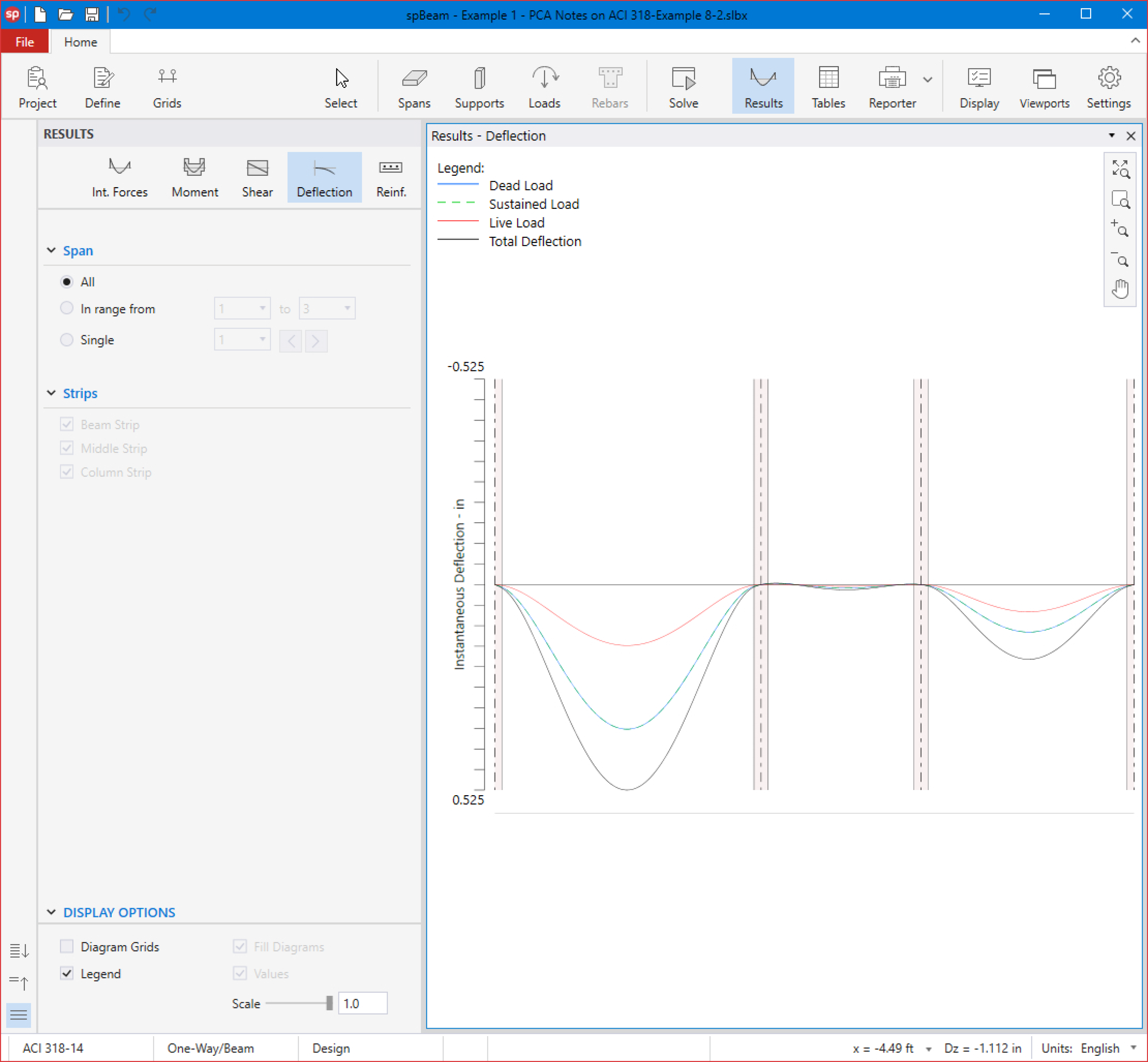
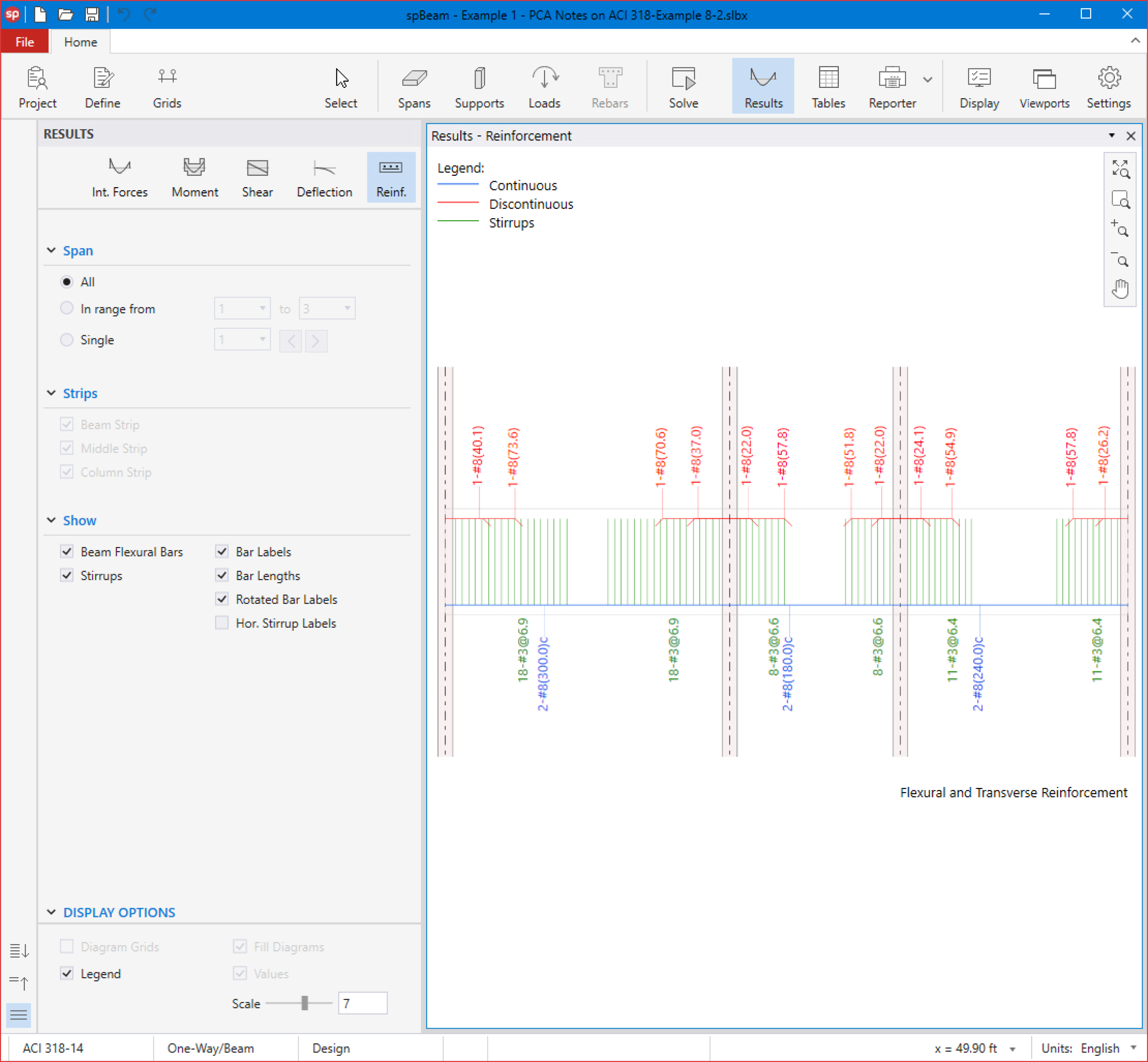
8.1.7. Viewing and Printing Results
15. After a successful run, results can be viewed by selecting Internal Forces, Moment Capacity, Shear Capacity, Deflection, or Reinforcement from the left panel.
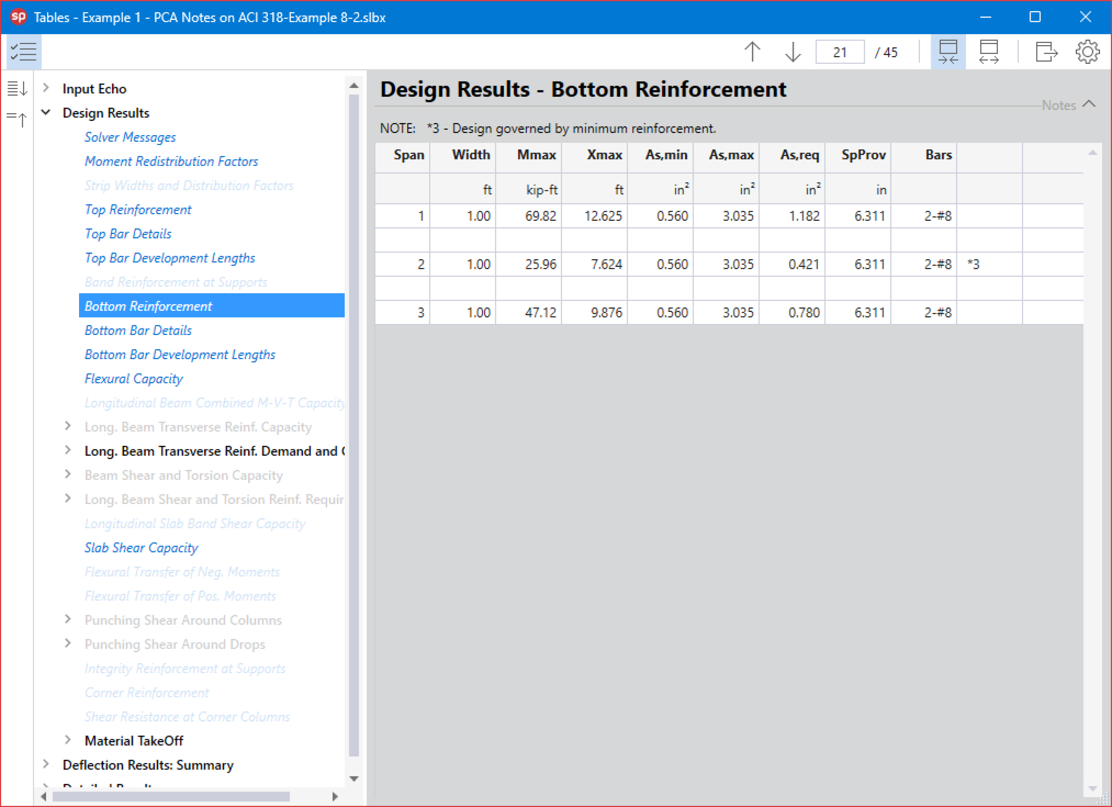
16. Results can be also viewed in table format by selecting the Tables command from the Ribbon.
17. Results can be printed or exported in different formats by selecting the Reporter command from the Ribbon.