spMats provides an efficient platform to model pile-supported foundations by treating piles as vertical springs within a finite element model. This allows engineers to simulate load transfer, assess pile reactions, and verify performance under various load combinations. Additionally, spMats integrates with spColumn, enabling users to export pile reactions and cross-sectional and material properties for detailed design and investigation of individual piles.
The following table shows a summary of important model results.
spMats Results Summary | |
For Pile Cap | |
As,provided (for areas where As,min governs) | #9 @ 8 in. |
As,provided (for areas where As,req governs) | #9 @ 8 in. + #9 @ 8 in. |
Maximum Uplift | 0.125 in. |
Maximum Settlement | 0.331 in. |
Punching Shear | Refer to Pile Cap Design Example |
For Piles | |
Pile Max. Comp. Reaction | 280.58 kips |
Pile Max. Tens. Reaction | 78.39 kips |
Pile Allow. Comp. Reaction | 230.00 kips |
Pile Allow. Tens. Reaction | 50.00 kips |
spColumn Results Summary | |
Pile Diameter | 16 in. |
Pile Reinforcement | 8 – #6 |
Pile Confinement | Tied Transverse Reinforcement |
5.1. Pile Boundary Condition Effect
In spMats, piles are assumed to be pinned to the pile cap leading to axial reactions on the piles that require designing the pile as a compression or tension member. In some cases, piles are fixed to the pile cap, which requires them to resist bending moments in one or both principal axes, in addition to the axial reaction. In this scenario, the pile needs to be treated as a member subjected to biaxial bending (Mx and My) due to the moments from both directions of analysis. This requires an investigation of the pile P-Mx-My interaction diagram in two directions simultaneously (axial force interaction with biaxial bending). This case study (for the case where the pile is fixed to the pile cap) shows the generation of the three-dimensional failure surface (biaxial Mx-My interaction diagram). Generating the three-dimensional failure surface (interaction diagram) for a pile section subjected to a combined axial force and biaxial bending moments is tedious and challenging for engineers and the use of a computer aid can save time and eliminate errors. StructurePoint's spColumn program can, quickly, simply, and accurately generate the three-dimensional failure surface (interaction diagram) for all commonly encountered pile sections in addition to highly complex and irregular cross-sections.
5.2. Tied vs. Spiral Lateral Reinforcement
The choice between tied and spiral confinement in pile design directly influences the strength reduction factors (ϕ) applied in capacity calculations. Spiral-confined piles benefit from higher ϕ values, such as 0.85 for axial compression and 0.75 for compression-controlled sections compared to 0.80 and 0.65 respectively for tied confinement, providing greater usable strength under the same conditions. These values are automatically applied in spColumn based on the selected confinement type. For this case study, tied confinement is sufficient, as demonstrated in the interaction diagram in Section 4.3.
Confinement choices selected by the user dictate the reduction factors for tied, spiral, and user defined types. User must ensure the final designed section is detailed correctly on design drawings in accordance with the corresponding provisions for confinement in the selected code to match the assumptions made in the model.
5.3. Applied Loads Modeling Considerations
When using FEA to model structures like the bridge pier supported by a pile cap in this case study, engineering judgment is essential in accurately determining how loads from the superstructure are transferred to the foundation model. If axial forces and bending moments from the bridge pier are modeled as concentrated point loads applied to a single node, stress concentrations may appear at that location. These concentrations are often numerical artifacts rather than true physical behavior. To reduce such localized effects and achieve more representative results, users can convert these point loads into equivalent area loads distributed over the pier footprint. This distributes the applied forces across multiple nodes, helping to smooth stress gradients and improve model behavior. The approach demonstrated in this case study is an expedient and conservative option for illustration and educational purposes only. It should not be interpreted as a prescriptive or recommended method. Engineers are advised to exercise professional judgment and adapt modeling techniques based on project-specific requirements and conditions.
spMats reports the required area of top and bottom flexural reinforcement per unit width [in.2/ft (US Customary Units) or mm2/m (Metric Units)] in both the X and Y directions. The total area of reinforcement in an element, then, can be obtained by multiplying the reported area of reinforcement by the width of the element.
Asx reinforcement is placed along X-direction and calculated based on the greater of the design moment, Mux, code minimum reinforcement ratio, or the base reinforcement ratio (if selected) specified by the user. Similarly, Asy reinforcement is placed along Y-direction and calculated based on the greater of the design moment, Muy, code minimum reinforcement ratio, or the base reinforcement ratio (if selected) specified by the user.
Using the conservative load application method in this case study, the provided reinforcement can be postulated based on the reinforcement contours in the following figures. The selection of the reinforcing bar size and spacing as well as the extent to which they are applied is left up to the engineer to choose based on project requirements and standard details. Figure 26 shows one possible reinforcement layout for illustration.
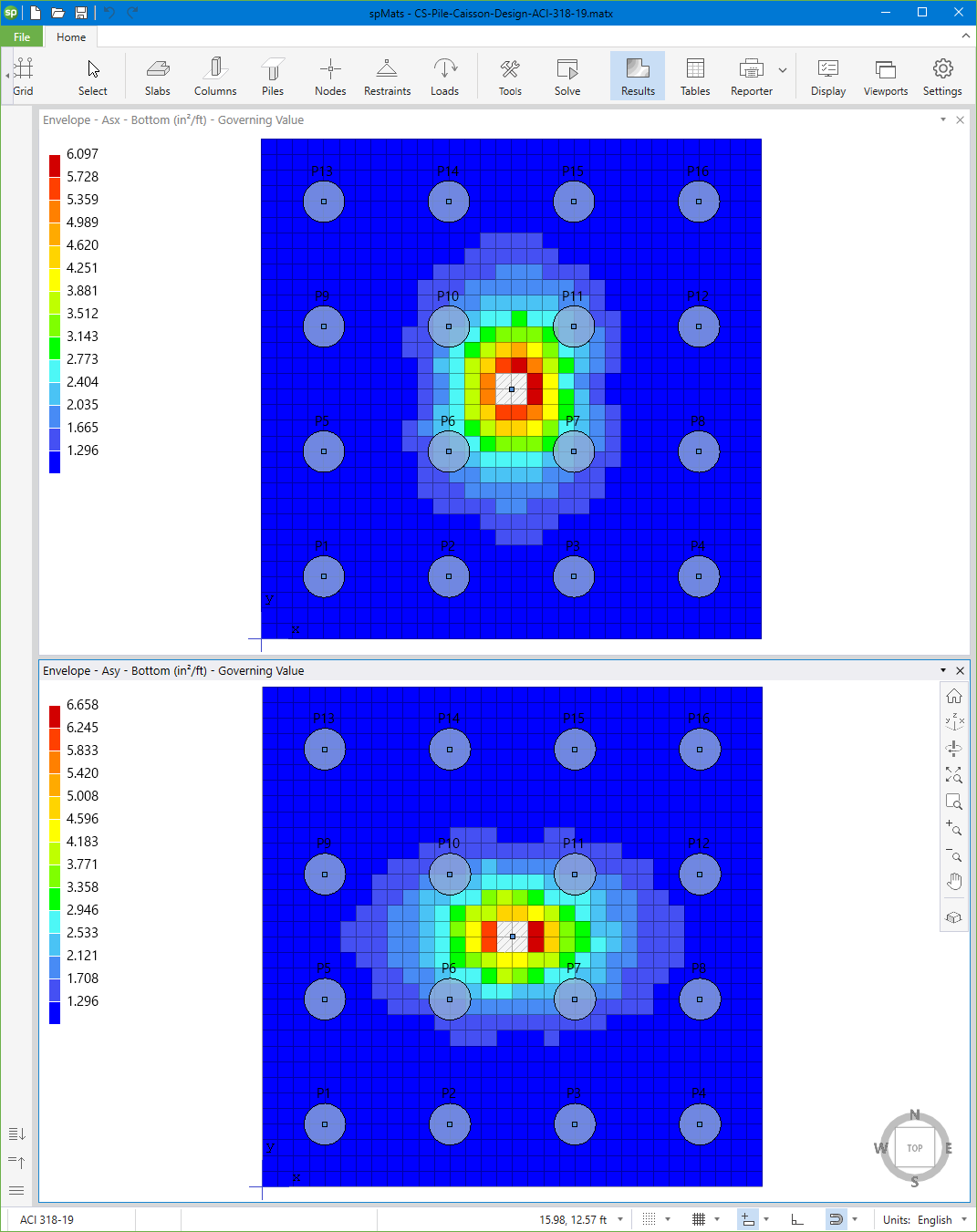
Figure 25 – Pile Cap Reinforcement (spMats)
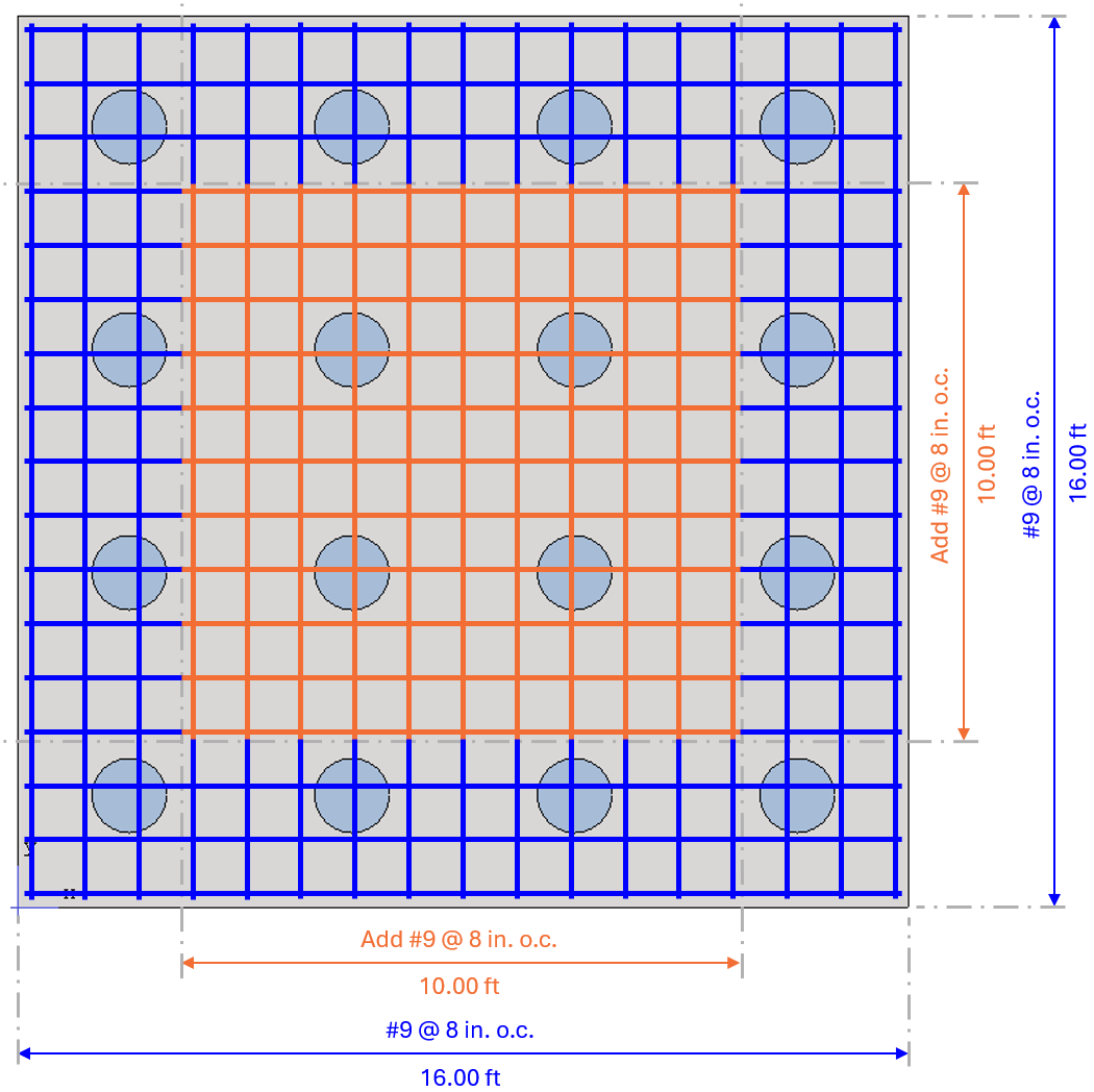
Figure 26 – Pile Cap Provided Reinforcement
5.5. Pile Settlement and Impact on Stiffness
The stiffness of each pile, represented by the spring constant Kp, plays a critical role in modeling pile-supported foundations. Kp is calculated as the ratio of the applied load Qu to the corresponding settlement S, which depends on pile geometry, material properties, and soil conditions. For cohesionless soils, settlement is estimated using an empirical formula incorporating pile diameter D, length L, cross-sectional area Ap, and modulus of elasticity Ep. Accurate estimation of pile settlement is essential, as it directly influences the stiffness input into the finite element model and therefore affects the load distribution and reaction forces in the overall foundation system. A project geotechnical report may present the values for pile stiffness and the expected maximum compression and tension permissible capacities. In some instances, the corresponding settlement or uplift at various load levels may also be provided to inform the model input and definitions. More information about this topic can be found in Section 2.3.2.2. in spMats Manual.