Based on the factored axial loads and magnified moments considering slenderness effects, the capacity of the assumed column section (500 mm × 500 mm with 12 – 25M bars distributed all sides equal) will be checked and confirmed to finalize the design. A column interaction diagram will be generated using strain compatibility analysis, the detailed procedure to develop column interaction diagram can be found in “Interaction Diagram - Tied Reinforced Concrete Column (CSA A23.3-19)” example.
The factored axial load resistance Pr for all load combinations will be set equals to Pf, then the factored moment resistance Mr associated to Pr will be compared with the magnified applied moment Mf. The design check for load combination #7 is shown below for illustration. The rest of the checks for the other load combinations are shown in the following Table.
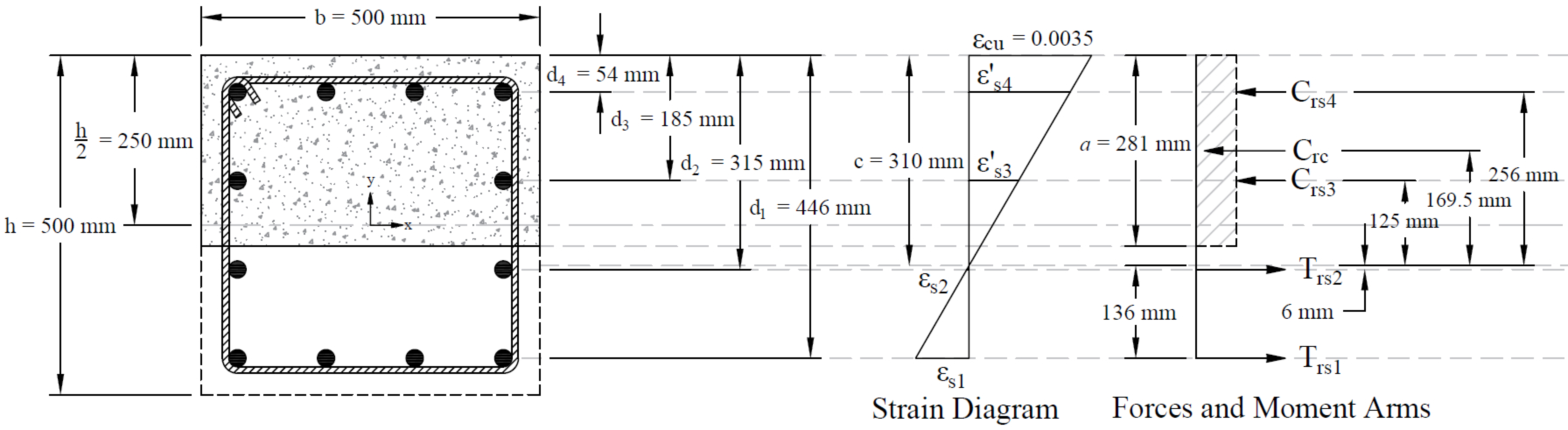
Figure 6 - Strains, Forces, and Moment Arms (Load Combination #7)
The following procedure is used to determine the nominal moment capacity by setting the factored axial load resistance, Pr, equal to the factored axial load, Pf and iterating on the location of the neutral axis.
6.1. c, a, and strains in the reinforcement
| |
Where c is the distance from extreme compression fiber to the neutral axis. | CSA A23.3-19 (3.2) |
| CSA A23.3-19 (10.1.7) |
Where: | |
| CSA A23.3-19 (Equation 10.2) |
| CSA A23.3-19 (10.1.3) |
| |
| |
| |
| CSA A23.3-19 (8.4.2) |
| CSA A23.3-19 (8.4.3(a)) |
| |
| |
| |


6.2. Forces in the concrete and steel
| CSA A23.3-19 (10.1.7a) |
Where: | |
| CSA A23.3-19 (Eq. 10.1) |
| |
| |
| |
| |
| |
| |
| |
| |
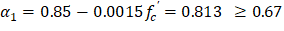
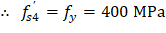
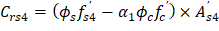
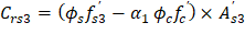
The area of the reinforcement in third and fourth layers has been included in the area (ab) used to compute Crc. As a result, it is necessary to subtract α1fc’ from fs’ before computing Crs: | |
| |
| |
| |


|
|
The assumed value of c = 309.66 mm is correct. |
|
|
|

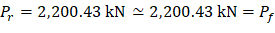


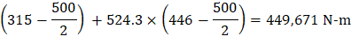
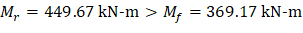
Table 6 - Exterior Column Axial and Moment Capacities | ||||||
No. | Pf, kN | Mf = M2(2nd), kN-m | c, mm | εt = εs | Pr, kN | Mr, kN-m |
1 | 2,261.28 | 165.20 | 313.85 | 0.00147 | 2,261.28 | 444.13 |
2 | 2,563.29 | 256.79 | 335.65 | 0.00115 | 2,563.29 | 415.70 |
3 | 2,563.29 | 312.32 | 335.65 | 0.00115 | 2,563.29 | 415.70 |
4 | 2,563.29 | 201.26 | 335.65 | 0.00115 | 2,563.29 | 415.70 |
5 | 1,997.97 | 267.47 | 296.18 | 0.00177 | 1,997.97 | 467.73 |
6 | 1,997.97 | 163.51 | 296.18 | 0.00177 | 1,997.97 | 467.73 |
7 | 2,200.43 | 369.17 | 309.66 | 0.00154 | 2,200.43 | 449.67 |
8 | 2,200.43 | 9.30 | 309.66 | 0.00154 | 2,200.43 | 449.67 |
9 | 1,635.11 | 316.54 | 266.94 | 0.00235 | 1,635.11 | 485.80 |
10 | 1,635.11 | -31.28 | 266.94 | 0.00235 | 1,635.11 | 485.80 |
Since Mr > Mf for all Pr = Pf, use 500 × 500 mm column with 12 - 25M bars.