5. Serviceability Requirements (Deflection Check)
Since the slab thickness was selected based on the minimum slab thickness tables in ACI 318-14, the deflection calculations are not required. However, the calculations of immediate and time-dependent deflections are covered in this section for illustration and comparison with spSlab model results.
5.1. Immediate (Instantaneous) Deflections
The calculation of deflections for two-way slabs is challenging even if linear elastic behavior can be assumed. Elastic analysis for three service load levels (D, D + Lsustained, D + LFull) is used to obtain immediate deflections of the two-way slab in this example. However, other procedures may be used if they result in predictions of deflection in reasonable agreement with the results of comprehensive tests.
ACI 318-14 (24.2.3) |
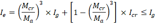
The effective moment of inertia (Ie) is used to account for the cracking effect on the flexural stiffness of the slab. Ie for uncracked section (Mcr > Ma) is equal to Ig. When the section is cracked (Mcr < Ma), then the following equation should be used:
| ACI 318-14 (Eq. 24.2.3.5a) | ||
Where: | |||
Ma | = | Maximum moment in member due to service loads at stage deflection is calculated. | |
The values of the maximum moments for the three service load levels are calculated from structural analysis as shown previously in this document. These moments are shown in Figure 19.
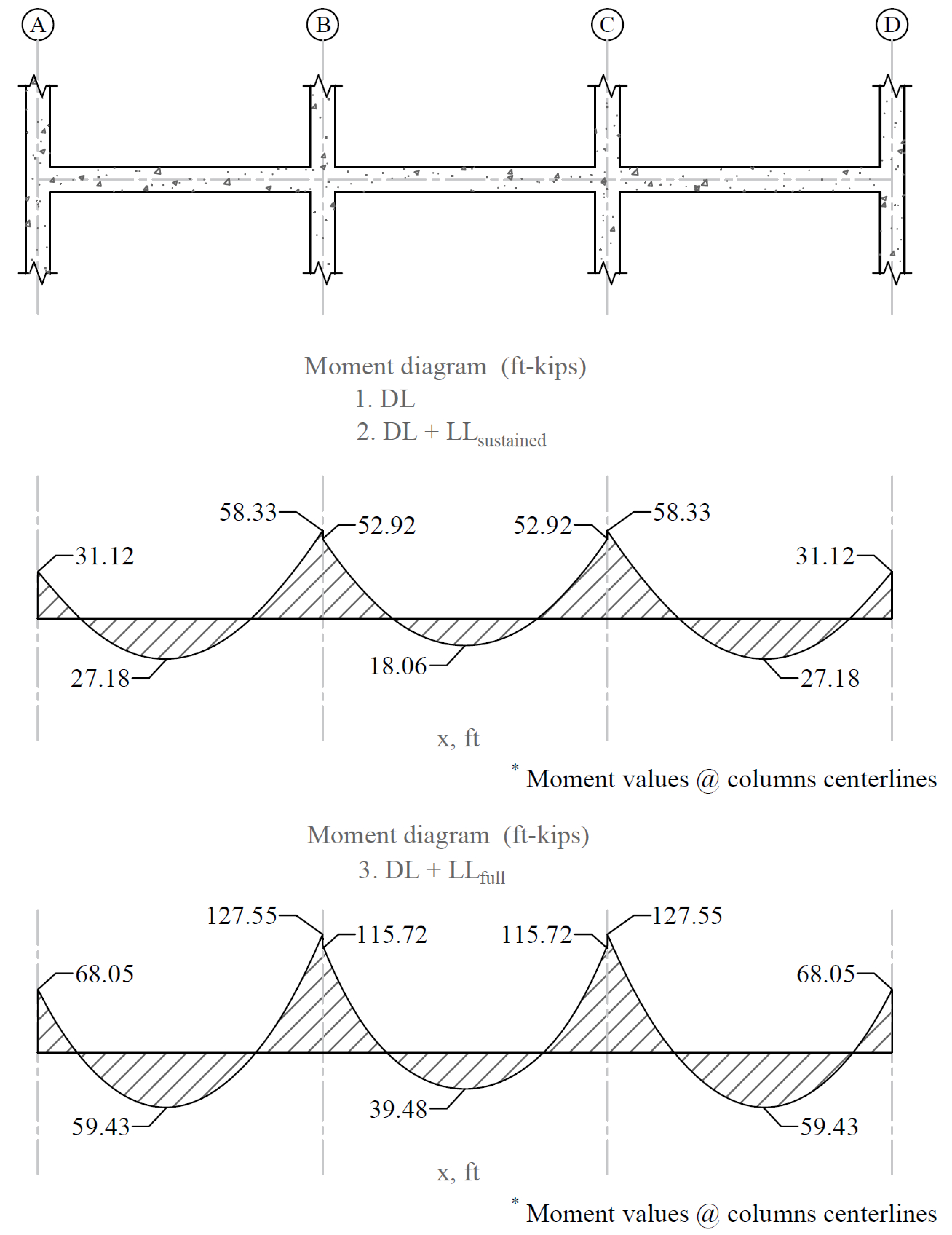
Figure 19 - Maximum Moments for the Three Service Load Levels
For positive moment (midspan) section of the exterior span:
Mcr | = | cracking moment. | |
| ACI 318-14 (Eq. 24.2.3.5b) | ||
fr | = | Modulus of rapture of concrete. | |
| ACI 318-14 (Eq. 19.2.3.1) | ||
Ig | = | Moment of inertia of the gross uncracked concrete section | |
Ig = 25,395.13 in.4 for T-section (see Figure 20) | |||
yt | = | Distance from centroidal axis of gross section, neglecting reinforcement, to tension face, in. | |
yt = 15.90 in. (see Figure 20) | |||
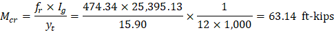

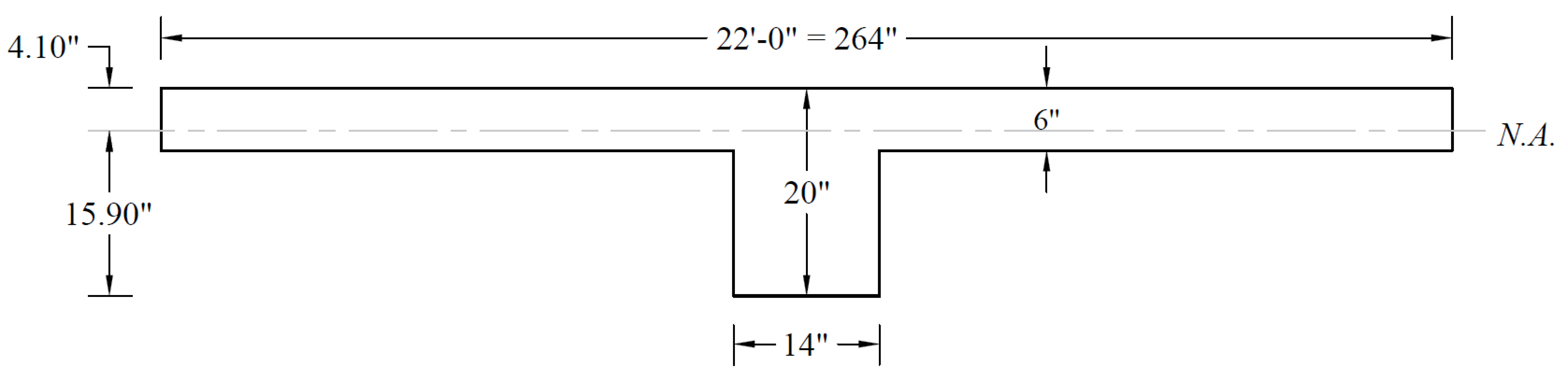
Figure 20 - Ig Calculations for Slab Section Near Support
Icr | = | moment of inertia of the cracked section transformed to concrete. | PCA Notes on ACI 318-11 (9.5.2.2) |
As calculated previously, the positive reinforcement for the end span frame strip is 22 #4 bars located at 1.0 in. along the slab section from the bottom of the slab and 4 #4 bars located at 1.75 in. along the beam section from the bottom of the beam. Five of the slab section bars are not continuous and will be excluded from the calculation of Icr. The Figure below shows all the parameters needed to calculate the moment of inertia of the cracked section transformed to concrete at midspan.
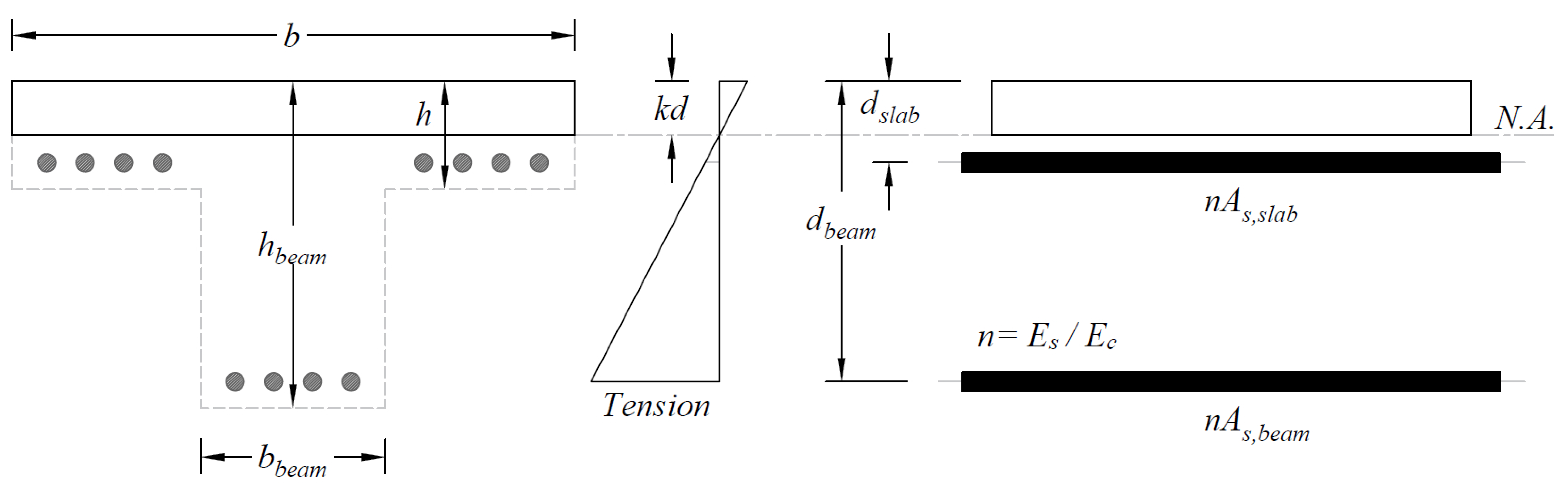
Figure 21 - Cracked Transformed Section (Positive Moment Section)
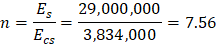
Ecs = Modulus of elasticity of slab concrete. ACI 318-14 (19.2.2.1.a) PCA Notes on ACI 318-11 (Table 10-2) 


For negative moment section (near the interior support of the end span):
The negative reinforcement for the end span frame strip near the interior support is 27 #4 bars located at 1.0 in. along the section from the top of the slab.
ACI 318-14 (Eq. 24.2.3.5b) ACI 318-14 (Eq. 19.2.3.1) 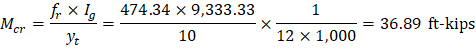

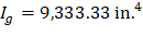
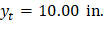
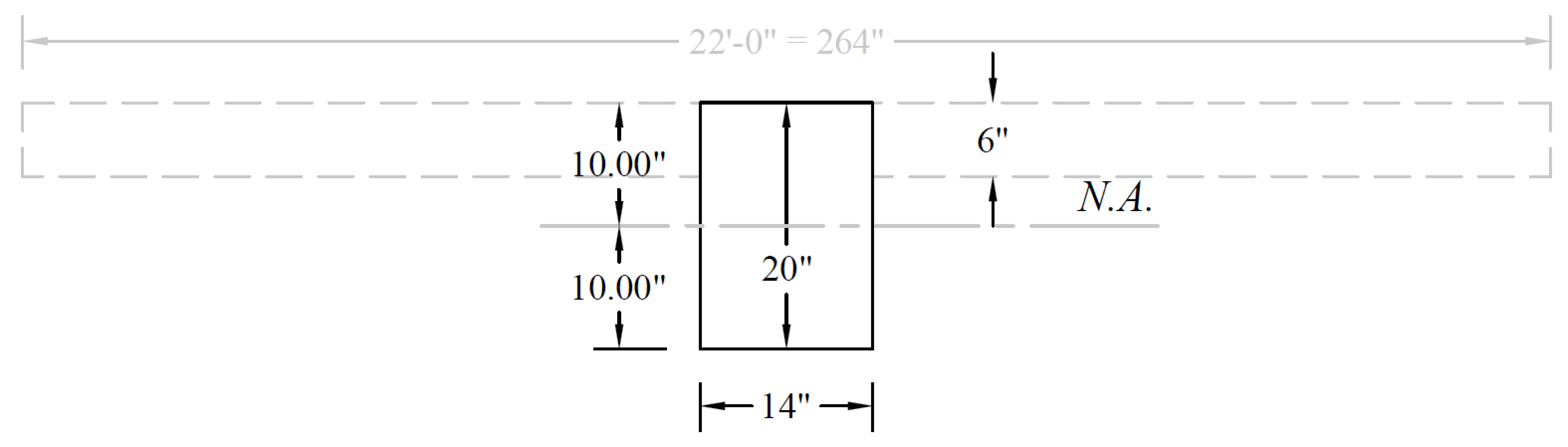
Figure 22 - Ig Calculations for Slab Section Near Support
ACI 318-14 (19.2.2.1.a) PCA Notes on ACI 318-11 (Table 10-2) PCA Notes on ACI 318-11 (Table 10-2) PCA Notes on ACI 318-11 (Table 10-2) PCA Notes on ACI 318-11 (Table 10-2)

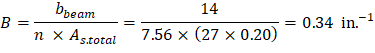
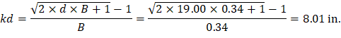
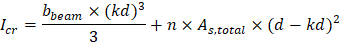


Figure 23 - Cracked Transformed Section (Interior Negative Moment Section for End Span)
The effective moment of inertia procedure described in the Code is considered sufficiently accurate to estimate deflections. The effective moment of inertia, Ie, was developed to provide a transition between the upper and lower bounds of Ig and Icr as a function of the ratio Mcr/Ma. For conventionally reinforced (nonprestressed) members, the effective moment of inertia, Ie, shall be calculated by Eq. (24.2.3.5a) unless obtained by a more comprehensive analysis.
Ie shall be permitted to be taken as the value obtained from Eq. (24.2.3.5a) at midspan for simple and continuous spans, and at the support for cantilevers.
ACI 318-14 (24.2.3.7) |
For continuous one-way slabs and beams. Ie shall be permitted to be taken as the average of values obtained from Eq. (24.2.3.5a) for the critical positive and negative moment sections.
ACI 318-14 (24.2.3.6) |
For the exterior span (span with one end continuous) with service load level (D+LLfull):
Since Mcr = 36.89 ft-kips < Ma = 127.55 ft-kips | |
ACI 318-14 (24.2.3.5a) | |
Where Ie- is the effective moment of inertia for the critical negative moment section (near the support). | |
| |
| |
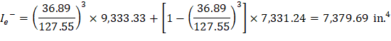

Where Ie+ is the effective moment of inertia for the critical positive moment section (midspan).
Since midspan stiffness (including the effect of cracking) has a dominant effect on deflections, midspan section is heavily represented in calculation of Ie and this is considered satisfactory in approximate deflection calculations.
The averaged effective moment of inertia (Ie,avg) is given by:
PCA Notes on ACI 318-11 (9.5.2.4(1)) Where: Ie- = The effective moment of inertia for the critical negative moment section near the support. Ie+ = The effective moment of inertia for the critical positive moment section (midspan). For the interior span (span with both ends continuous) with service load level (D+LLfull): Since Mcr = 36.89 ft-kips < Ma = 115.72 ft-kips ACI 318-14 (24.2.3.5a) The averaged effective moment of inertia (Ie,avg) is given by: PCA Notes on ACI 318-11 (9.5.2.4(2)) Where: Ie,l- = The effective moment of inertia for the critical negative moment section near the left support. Ie,r- = The effective moment of inertia for the critical negative moment section near the right support.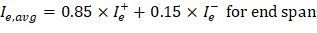


The following Table provides a summary of the required parameters and calculated values needed for deflections for exterior and interior equivalent frame. It also provides a summary of the same values for column strip and middle strip to facilitate calculation of panel deflection.
Table 6 - Averaged Effective Moment of Inertia Calculations | |||||||||||||
For Frame Strip | |||||||||||||
Span | Zone | Ig | Icr | Ma (ft-kips) | Mcr | Ie (in.4) | Ie,avg (in.4) | ||||||
D | D + | D + | D | D + | D + | D | D + | D + | |||||
Left | 9,333 | 7,147 | -30.60 | -30.60 | -66.91 | 36.89 | 9,333 | 9,333 | 7,513 | 22,762 | 22,762 | 22,693 | |
Midspan | 25,395 | 2,282 | 27.18 | 27.18 | 59.43 | 63.14 | 25,395 | 25,395 | 25,395 | ||||
Right | 9,333 | 7,331 | -58.33 | -58.33 | -127.55 | 36.89 | 7,838 | 7,838 | 7,380 | ||||
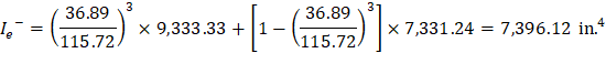
Left | 9,333 | 7,331 | -52.92 | -52.92 | -115.72 | 36.89 | 8,009 | 8,009 | 7,396 | 20,179 | 20,179 | 19,995 | |
Mid | 25,395 | 1,553 | 18.06 | 18.06 | 39.48 | 63.14 | 25,395 | 25,395 | 25,395 | ||||
Right | 9,333 | 7,331 | -52.92 | -52.92 | -115.72 | 36.89 | 8,009 | 8,009 | 7,396 | ||||
Deflections in two-way slab systems shall be calculated taking into account size and shape of the panel, conditions of support, and nature of restraints at the panel edges. For immediate deflections in two-way slab systems, the midpanel deflection is computed as the sum of deflection at midspan of the column strip or column line in one direction (Δcx or Δcy) and deflection at midspan of the middle strip in the orthogonal direction (Δmx or Δmy). Figure 24 shows the deflection computation for a rectangular panel. The average Δ for panels that have different properties in the two direction is calculated as follows:
| PCA Notes on ACI 318-11 (9.5.3.4 Eq. 8) |
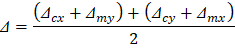
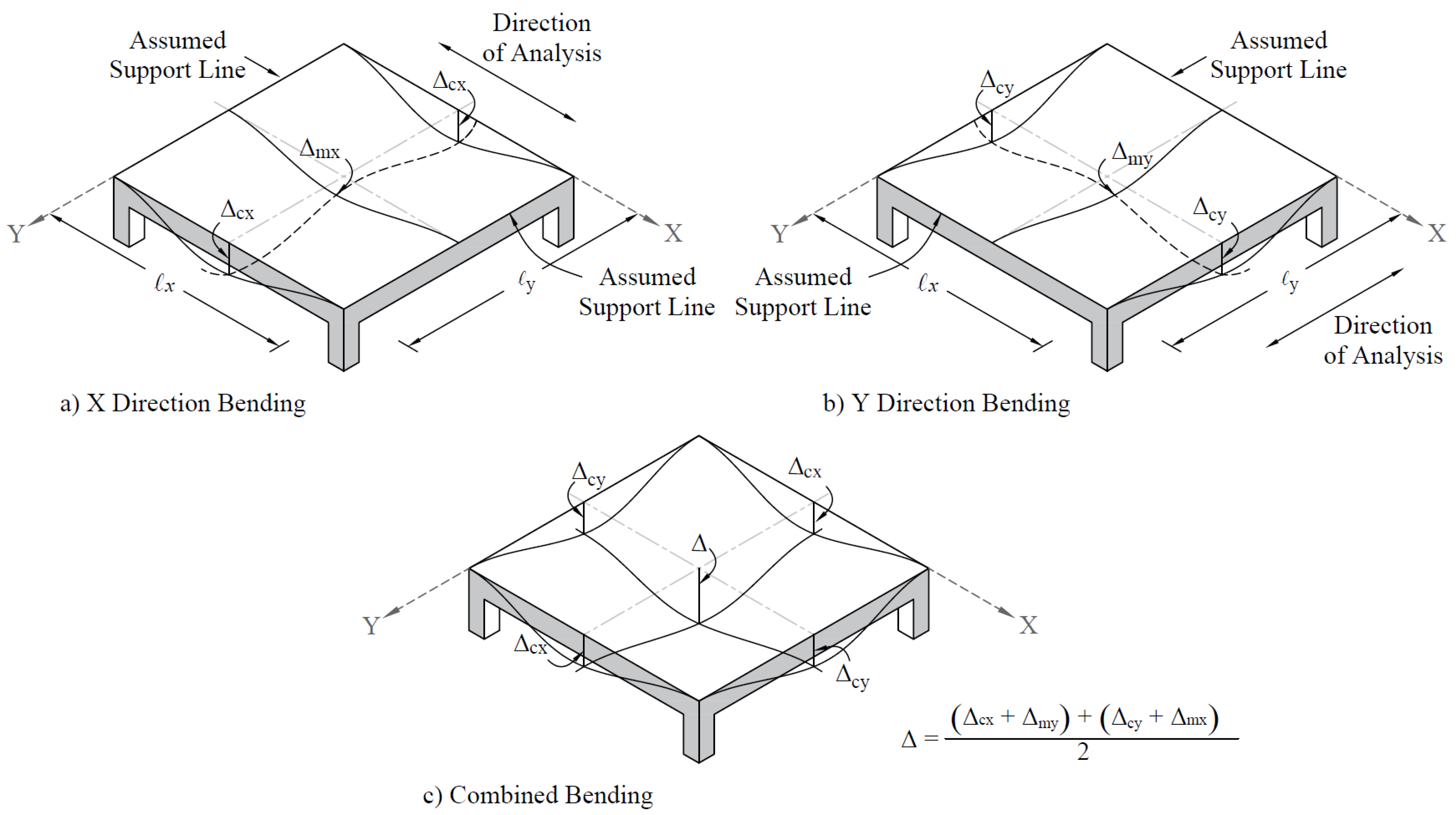
Figure 24 - Deflection Computation for a Rectangular Panel
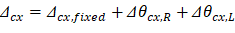
To calculate each term of the previous equation, the following procedure should be used. Figure 25 shows the procedure of calculating the term Δcx. Same procedure can be used to find the other terms.
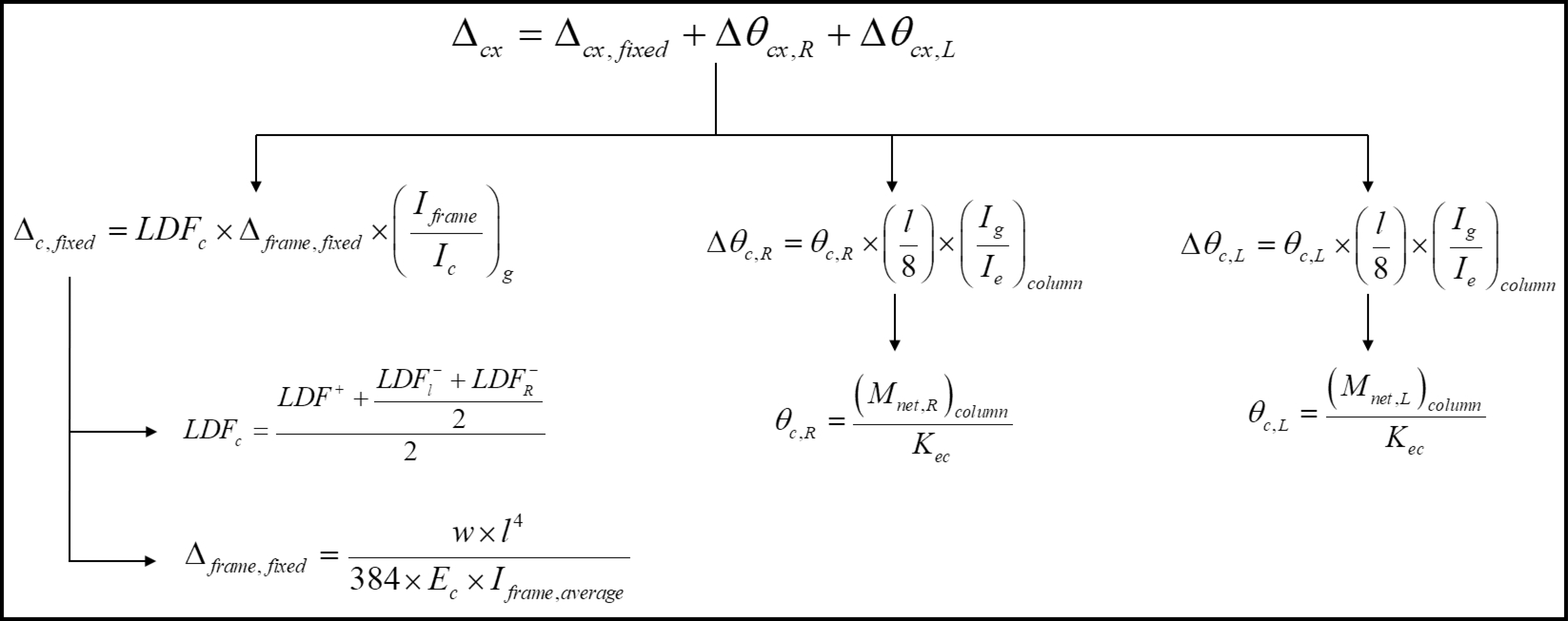
Figure 25 – Δcx Calculation Procedure
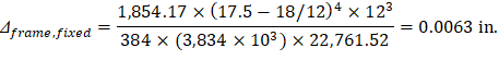
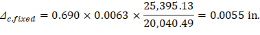
For exterior span - service dead load case: PCA Notes on ACI 318-11 (9.5.3.4 Eq. 10) Where: Δframe,fixed = Deflection of column strip assuming fixed-end condition. ACI 318-14 (19.2.2.1.a) Iframe,averaged = The averaged effective moment of inertia (Ie,avg) for the frame strip for service dead load case from Table 6 = 22,761.52 in.4 PCA Notes on ACI 318-11 (9.5.3.4 Eq. 11)

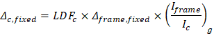
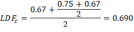
Where LDFc is the load distribution factor for the column strip. The load distribution factor for the column strip can be found from the following equation:
And the load distribution factor for the middle strip can be found from the following equation:
For the end span, LDF for exterior negative region (LDFL¯), interior negative region (LDFR¯), and positive region (LDFL+) are 0.75, 0.67, and 0.67, respectively (From Table 2 of this document). Thus, the load distribution factor for the column strip for the end span is given by:
Ic,g | = | The gross moment of inertia (Ig) for the column strip (for T section) = 20,040.49 in.4 | |
Iframe,g | = | The gross moment of inertia (Ig) for the frame strip (for T section) = 25,395.13 in.4 |
| PCA Notes on ACI 318-11 (9.5.3.4 Eq. 12) | ||
Where: | |||
θc,L | = | Rotation of the span left support | |
(Mnet,L)frame | = | 31.12 ft-kips = Net frame strip negative moment of the left support | |
Kec | = | Effective column stiffness for exterior column = 763.33 × Ec = 2,927 × 106 in.-lb (calculated previously). | |
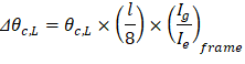
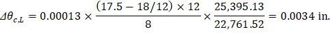
PCA Notes on ACI 318-11 (9.5.3.4 Eq. 14) Where: Δθc,L = Midspan deflection due to rotation of left support. (Ig / Ie)frame = Gross to effective moment of inertia ratio for frame strip.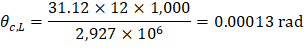
| ||
| ||
Where: | ||
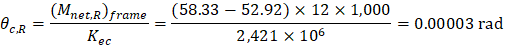
θc,R | = | Rotation of the span right support. |
(Mnet,R)frame | = | Net frame strip negative moment of the right support. |
Kec | = | Effective column stiffness for interior column = 631.36 × Ec = 2,421 × 106 in.-lb (calculated previously). |
| ||
Where: | ||
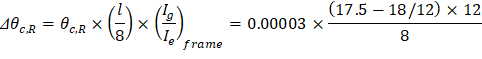
Δθc,R | = | Midspan deflection due to rotation of right support. |
| PCA Notes on ACI 318-11 (9.5.3.4 Eq. 9) |
|

Following the same procedure, Δmx can be calculated for the middle strip. This procedure is repeated for the equivalent frame in the orthogonal direction to obtain Δcy, and Δmy for the end and middle spans for the other load levels (D + LLsus and D + LLfull).
Assuming square panel, Δcx = Δcy= 0.010 in. and Δmx = Δmy= 0.021 in.
The average Δ for the corner panel is calculated as follows:
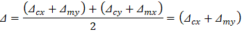
Table 7 - Instantaneous Deflections | |||||||||||||||||
Column Strip | Middle Strip | ||||||||||||||||
Span | LDF | D | LDF | D | |||||||||||||
Δframe-fixed (in.) | Δc-fixed (in.) | θc1 (rad) | θc2 (rad) | Δθc1 (in.) | Δθc2 (in.) | Δcx (in.) | Δframe-fixed (in.) | Δm-fixed (in.) | θm1 (rad) | θm2 (rad) | Δθm1 (in.) | Δθm2 (in.) | Δmx (in.) | ||||
Ext | 0.69 | 0.0063 | 0.0055 | 0.00013 | 0.00003 | 0.0034 | 0.0007 | 0.010 | 0.31 | 0.0063 | 0.0172 | 0.00013 | 0.00003 | 0.0034 | 0.0007 | 0.021 | |
Int | 0.67 | 0.0071 | 0.0060 | 0.00003 | 0.00003 | -0.0008 | -0.0008 | 0.004 | 0.33 | 0.0071 | 0.0207 | 0.00003 | 0.00003 | -0.0008 | -0.0008 | 0.019 | |
Span | LDF | D+LLsus | LDF | D+LLsus | |||||||||||||
Δframe-fixed (in.) | Δc-fixed (in.) | θc1 (rad) | θc2 (rad) | Δθc1 (in.) | Δθc2 (in.) | Δcx (in.) | Δframe-fixed (in.) | Δm-fixed (in.) | θm1 (rad) | θm2 (rad) | Δθm1 (in.) | Δθm2 (in.) | Δmx (in.) | ||||
Ext | 0.69 | 0.0063 | 0.0055 | 0.00013 | 0.00003 | 0.0034 | 0.0007 | 0.010 | 0.31 | 0.0063 | 0.0172 | 0.00013 | 0.00003 | 0.0034 | 0.0007 | 0.021 | |
Int | 0.67 | 0.0071 | 0.0060 | 0.00003 | 0.00003 | -0.0008 | -0.0008 | 0.004 | 0.33 | 0.0071 | 0.0207 | 0.00003 | 0.00003 | -0.0008 | -0.0008 | 0.019 | |
Span | LDF | D+LLfull | LDF | D+LLfull | |||||||||||||
Δframe-fixed (in.) | Δc-fixed (in.) | θc1 (rad) | θc2 (rad) | Δθc1 (in.) | Δθc2 (in.) | Δcx (in.) | Δframe-fixed (in.) | Δm-fixed (in.) | θm1 (rad) | θm2 (rad) | Δθm1 (in.) | Δθm2 (in.) | Δmx (in.) | ||||
Ext | 0.69 | 0.0137 | 0.0120 | 0.00028 | 0.00006 | 0.0075 | 0.0016 | 0.021 | 0.31 | 0.0137 | 0.0378 | 0.00028 | 0.00006 | 0.0075 | 0.0016 | 0.047 | |
Int | 0.67 | 0.0156 | 0.0132 | 0.00006 | 0.00006 | -0.0018 | -0.0018 | 0.010 | 0.33 | 0.0156 | 0.0457 | 0.00006 | 0.00006 | -0.0018 | -0.0018 | 0.042 | |
Span | LDF | LL | LDF | LL | |||||||||||||
Δcx (in.) | Δmx (in.) | ||||||||||||||||
Ext | 0.69 | 0.011 | 0.31 | 0.025 | |||||||||||||
Int | 0.67 | 0.005 | 0.33 | 0.023 | |||||||||||||
5.2. Time-Dependent (Long-Term) Deflections (Δlt)
The additional time-dependent (long-term) deflection resulting from creep and shrinkage (Δcs) may be estimated as follows:
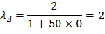
PCA Notes on ACI 318-11 (9.5.2.5 Eq. 4) The total time-dependent (long-term) deflection is calculated as: CSA A23.3-04 (N9.8.2.5) Where: (Δsust)Inst = Immediate (instantaneous) deflection due to sustained load, in. ACI 318-14 (24.2.4.1.1) (Δtotal)lt = Time-dependent (long-term) total deflection, in. (Δtotal)Inst = Total immediate (instantaneous) deflection, in. For the exterior span ξ = 2, consider the sustained load duration to be 60 months or more. ACI 318-14 (Table 24.2.4.1.3) ρ` = 0, conservatively.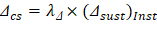

The following Table shows long-term deflections for the exterior and interior spans for the analysis in the x-direction, for column and middle strips.
Table 8 - Long-Term Deflections | |||||
Column Strip | |||||
Span | (Δsust)Inst (in.) | λΔ | Δcs (in.) | (Δtotal)Inst (in.) | (Δtotal)lt (in.) |
Exterior | 0.010 | 2 | 0.019 | 0.021 | 0.040 |
Interior | 0.004 | 2 | 0.009 | 0.010 | 0.018 |
Middle Strip | |||||
Exterior | 0.021 | 2 | 0.043 | 0.047 | 0.090 |
Interior | 0.019 | 2 | 0.038 | 0.042 | 0.080 |