Shear strength of the slab in the vicinity of columns/supports includes an evaluation of one-way shear (beam action) and two-way shear (punching) in accordance with ACI 318 Chapter 22.
4.1. One-Way (Beam Action) Shear Strength
ACI 318-14 (22.5)
One-way shear is critical at a distance d from the face of the column as shown in Figure 3. Figure 24 and Figure 26 show the factored shear forces (Vu) at the critical sections around each column and each drop panel, respectively. In members without shear reinforcement, the design shear capacity of the section equals to the design shear capacity of the concrete:
| ACI 318-14 (Eq. 22.5.1.1) |
Where: | |
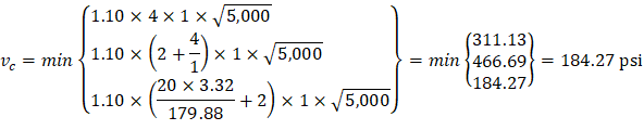
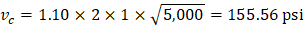
| ACI 318-14 (Eq. 22.5.5.1) |
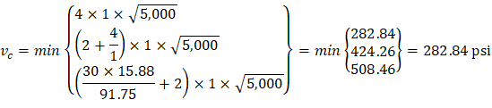
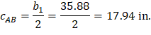
One-way shear capacity is calculated assuming the shear cross-section area consisting of the drop panel (if any), the ribs, and the slab portion above them, decreased by concrete cover. For such section the equivalent shear width for single rib is calculated from the formula: | |
| spSlab Software Manual (Eq. 2-13) |
Where: | |
b = rib width, in. | |
d = distance from extreme compression fiber to tension reinforcement centroid. | |

4.1.1. At Distance d from the Supporting Column
for middle span with #6 reinforcement.
Where λ = 1 for normal weight concrete
(see the Figure 23)
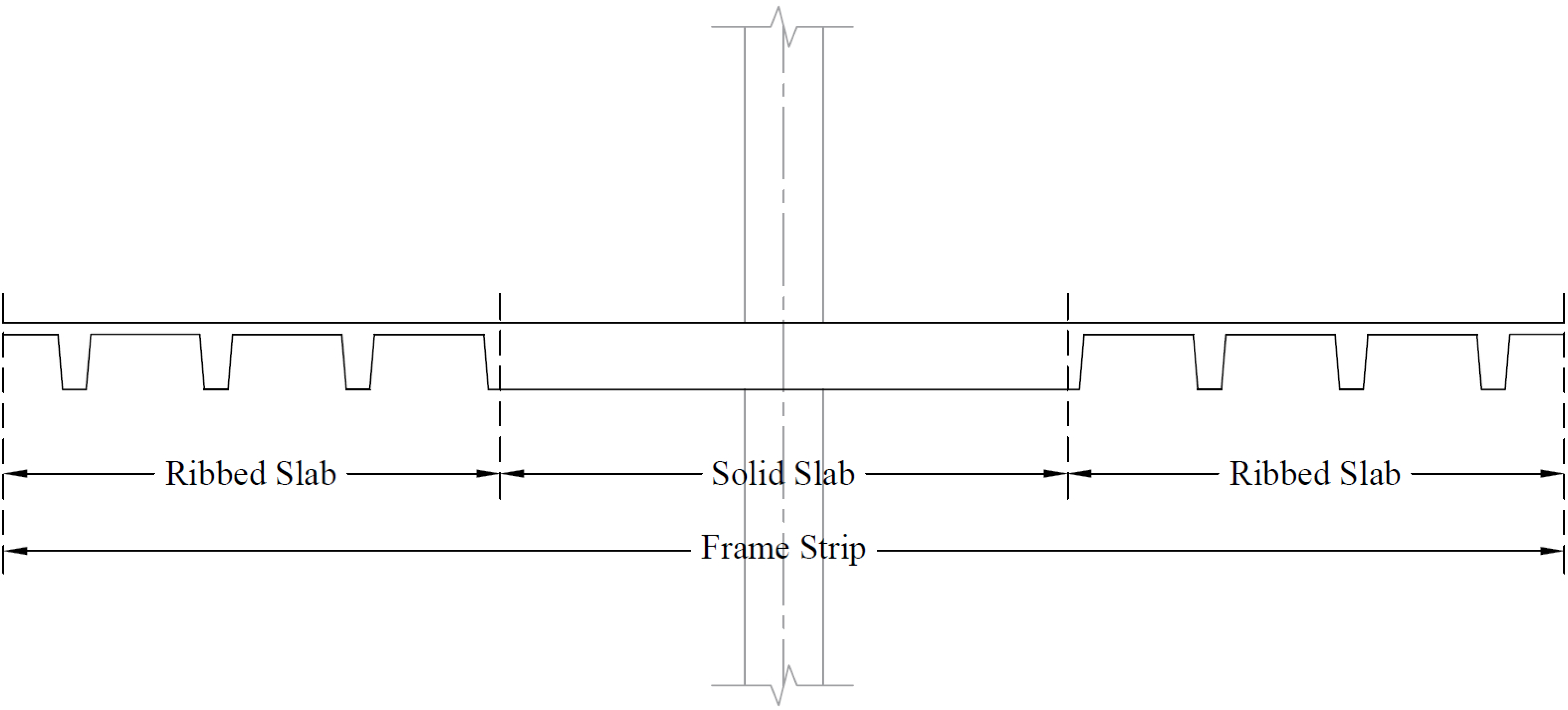
Figure 23 – Frame Strip Cross Section (at Distance d from the Face of the Supporting Column)
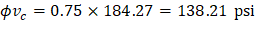
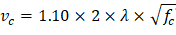
The one-way shear capacity for the ribbed slab portions shown in Figure 23 is permitted to be increased by 10%.
ACI 318-14 (9.8.1.5)

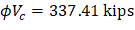
Because ϕVc ≥ Vu at all the critical sections, the slab has adequate one-way shear strength.
Figure 24 - One-way Shear at Critical Sections (at Distance d from the Face of the Supporting Column)
4.1.2. At the Face of the Drop Panel
for middle span with #6 reinforcement.

Where λ = 1 for normal weight concrete
(see the Figure 25)
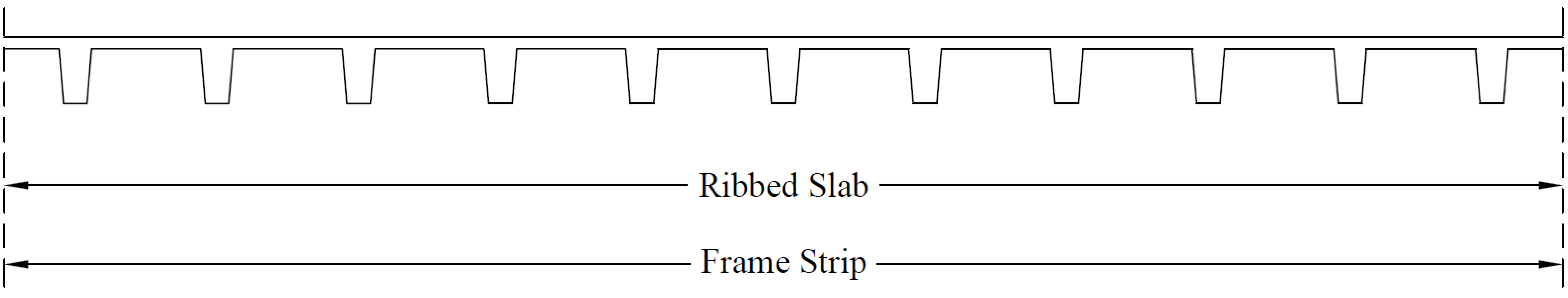
Figure 25 – Frame Strip Cross Section (at Distance d from the Face of the Drop Panel)
The one-way shear capacity for the ribbed slab portions shown in Figure 25 is permitted to be increased by 10%.
ACI 318-14 (9.8.1.5)

Because ϕVc ≥ Vu at all the critical sections, the slab has adequate one-way shear strength.
Figure 26 - One-Way Shear at Critical Sections (at the Face of the Drop Panel)
4.2. Two-Way (Punching) Shear Strength
ACI 318-14 (22.6)
4.2.1. Around the Columns Faces
Two-way shear is critical on a rectangular section located at d/2 away from the face of the column as shown in Figure 20.
a) Exterior column:
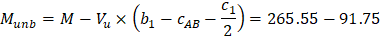
The factored shear force (Vu) in the critical section is computed as the reaction at the centroid of the critical section minus the self-weight and any superimposed surface dead and live load acting within the critical section (d/2 away from column face).

The factored unbalanced moment used for shear transfer, Munb, is computed as the sum of the joint moments to the left and right. Moment of the vertical reaction with respect to the centroid of the critical section is also taken into account.
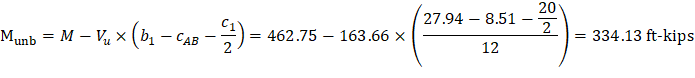
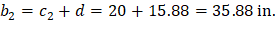
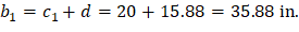
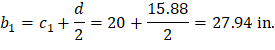
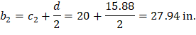
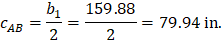
For the exterior column in Figure 18 the location of the centroidal axis z-z is:

Where:
|
| |
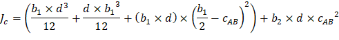
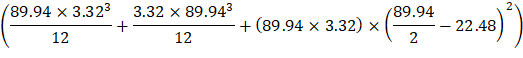
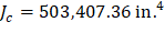
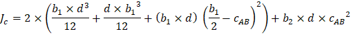
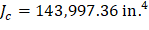
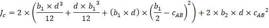
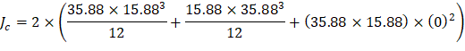
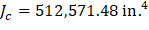
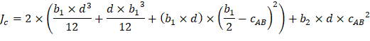
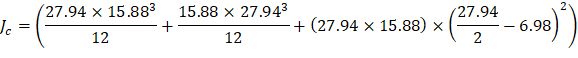
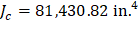
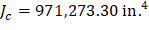
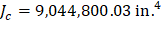
The polar moment Jc of the shear perimeter is: | ||
| ||
| ||
| ||
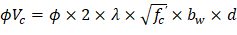
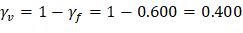
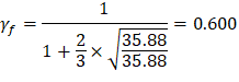
| ACI 318-14 (Eq. 8.4.4.2.2) | |
Where: | ||
| ACI 318-14 (8.4.2.3.2) | |
| ||
The length of the critical perimeter for the exterior column: | ||
| ||
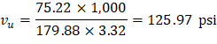
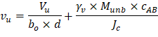
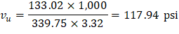
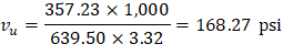
The two-way shear stress (vu) can then be calculated as: | ||
| ACI 318-14 (R.8.4.4.2.3) | |
| ||
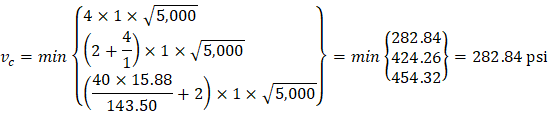
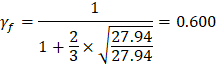
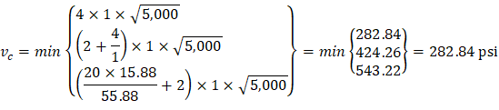
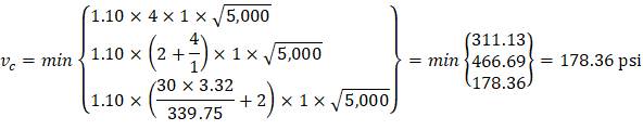
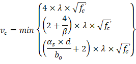
| ACI 318-14 (Table 22.6.5.2) | |
| ||
| ||
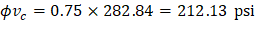
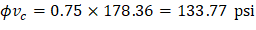
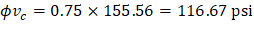
Because ϕvc ≥ vu at the critical section, the slab has adequate two-way shear strength at this joint. | ||


b) Interior column:


For the interior column in Figure 18, the location of the centroidal axis z-z is:
Where:
|
| |
The polar moment Jc of the shear perimeter is: | ||
| ||
| ||
| ||
| ACI 318-14 (Eq. 8.4.4.2.2) | |
Where: | ||
| ACI 318-14 (8.4.2.3.2) | |
| ||
The length of the critical perimeter for the interior column: | ||
| ||
The two-way shear stress (vu) can then be calculated as: | ||
| ACI 318-14 (R.8.4.4.2.3) | |
| ||
| ACI 318-14 (Table 22.6.5.2) | |
| ||
| ||
Since ϕvc ≥ vu at the critical section, the slab has adequate two-way shear strength at this joint. | ||


c) Corner column:
In this example, interior equivalent frame strip was selected where it only have exterior and interior supports (no corner supports are included in this strip). However, the two-way shear strength of corner supports usually governs. Thus, the two-way shear strength for the corner column in this example will be checked for educational purposes. Same procedure is used to find the reaction and factored unbalanced moment used for shear transfer at the centroid of the critical section for the corner support for the exterior equivalent frame strip.
For the corner column in Figure 18, the location of the centroidal axis z-z is:

Where:
|
| |
The polar moment Jc of the shear perimeter is: | ||
| ||
| ||
| ||
| ACI 318-14 (Eq. 8.4.4.2.2) | |
Where: | ||
| ACI 318-14 (8.4.2.3.2) | |
| ||
The length of the critical perimeter for the corner column: | ||
| ||
The two-way shear stress (vu) can then be calculated as: | ||
| ACI 318-14 (R.8.4.4.2.3) | |
| ||
| ACI 318-14 (Table 22.6.5.2) | |
| ||
| ||
Since ϕvc ≥ vu at the critical section, the slab has adequate two-way shear strength at this joint. | ||


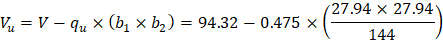
Two-way shear is critical on a rectangular section located at d/2 away from the face of the drop panel.
The factored shear force (Vu) in the critical section is computed as the reaction at the centroid of the critical section minus the self-weight and any superimposed surface dead and live load acting within the critical section (d/2 away from column face).
Note: For simplicity, it is conservative to deduct only the self-weight of the slab and joists in the critical section from the shear reaction in punching shear calculations. This approach is also adopted in the spSlab program for the punching shear check around the drop panels.
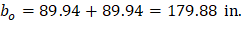
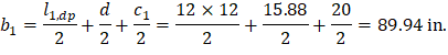
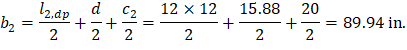
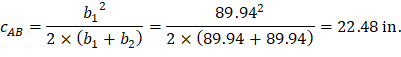
a) Exterior drop panel:

d value is used in the calculation of vu is given by (see the Figure 27).
| spSlab Software Manual (Eq. 2-14) | |
| ||
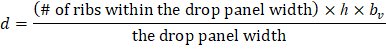
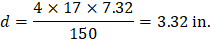
Figure 27 – Equivalent Thickness based on Shear Area Calculation
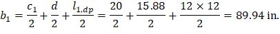
The length of the critical perimeter for the exterior drop panel: | ||
| ||
Where: | ||
|
| |
| ||
The polar moment Jc of the shear perimeter is: | ||
| ||
| ||
| ||
The two-way shear stress (vu) can then be calculated as: | ||
ACI 318-14 (R.8.4.4.2.3) | ||
| ||
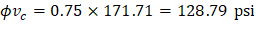
The two-way shear capacity for the ribbed slab is permitted to be increased by 10%. | ACI 318-14 (9.8.1.5) | |
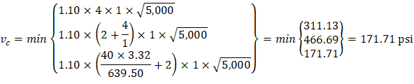
| ACI 318-14 (Table 22.6.5.2) | |
| ||
| ||
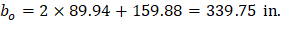


In waffle slab design where the drop panels create a large critical shear perimeter, the factor (bo/d) has limited contribution and is traditionally neglected for simplicity and conservatism. This approach is adopted in this calculation and in the spSlab program (spSlab software manual, Eq. 2-46).
The two-way shear capacity for the ribbed slab is permitted to be increased by 10%. | ACI 318-14 (9.8.1.5) | |
| spSlab Software Manual (Eq. 2-46) | |
| ||
| ||
Since ϕvc < vu at the critical section, the slab does not have adequate two-way shear strength around this drop panel. | ||


b) Interior drop panel:
| ||
The length of the critical perimeter for the interior drop panel: | ||
| ||
Where: | ||
|
| |
| ||
The polar moment Jc of the shear perimeter is: | ||
| ||
| ||
| ||
The two-way shear stress (vu) can then be calculated as: | ||
| ACI 318-14 (R.8.4.4.2.3) | |
| ||
The two-way shear capacity for the ribbed slab is permitted to be increased by 10%. | ACI 318-14 (9.8.1.5) | |
| ACI 318-14 (Table 22.6.5.2) | |
| ||
| ||
| spSlab Software Manual (Eq. 2-46) | |
| ||
| ||
Since ϕvc < vu at the critical section, the slab does not have adequate two-way shear strength around this drop panel. | ||


c) Corner drop panel:
| ||
The length of the critical perimeter for the corner drop panel: | ||
| ||
Where: | ||
|
| |
| ||
The polar moment Jc of the shear perimeter is: | ||
| ||
| ||
| ||
The two-way shear stress (vu) can then be calculated as: | ||
| ACI 318-14 (R.8.4.4.2.3) | |
| ||
The two-way shear capacity for the ribbed slab is permitted to be increased by 10%. | ACI 318-14 (9.8.1.5) | |
| ACI 318-14 (Table 22.6.5.2) | |
| ||
| ||
| spSlab Software Manual (Eq. 2-46) | |
| ||
| ||
Because ϕvc < vu at the critical section, the slab does not have adequate two-way shear strength around this drop panel. | ||
To mitigate the deficiency in two-way shear capacity an evaluation of possible options is required: | ||
1. Increase the thickness of the slab system. | ||
2. Increasing the dimensions of the drop panels (length and/or width) | ||
3. Increasing the concrete strength | ||
4. Reduction of the applied loads | ||
5. Reduction of the panel spans | ||
6. Using less conservative punching shear allowable (gain of 5-10%) | ||
7. Refine the deduction of drop panel weight from the shear reaction (gain of 2-5%) | ||
This example will be continued without the required modification discussed above to continue the illustration of the analysis and design procedure. | ||