Building Code Requirements for Structural Concrete (ACI 318-19) and Commentary (ACI 318R-19)
• Reinforced Concrete Design, 9th Edition, 2021, Pincheira J. et. al., Oxford University Press, Example 10.18.1
• spColumn Engineering Software Program Manual v10.00, STRUCTUREPOINT, 2021
• “Interaction Diagram - Tied Reinforced Concrete Column Design Strength (ACI 318-19)” Design Example, STRUCTUREPOINT, 2022
• “Interaction Diagram - Tied Reinforced Concrete Column with High-Strength Reinforcing Bars (ACI 318-19)” Design Example, STRUCTUREPOINT, 2022
• “Interaction Diagram - Barbell Concrete Shear Wall Unsymmetrical Boundary Elements (ACI 318-19)” Design Example, STRUCTUREPOINT, 2022
• “Interaction Diagram - Building Elevator Reinforced Concrete Core Wall Design Strength (ACI 318-19)” Design Example, STRUCTUREPOINT, 2022
Stirrups, longitudinal reinforcement and reinforcement locations are shown in Figure 1 and Table 1.
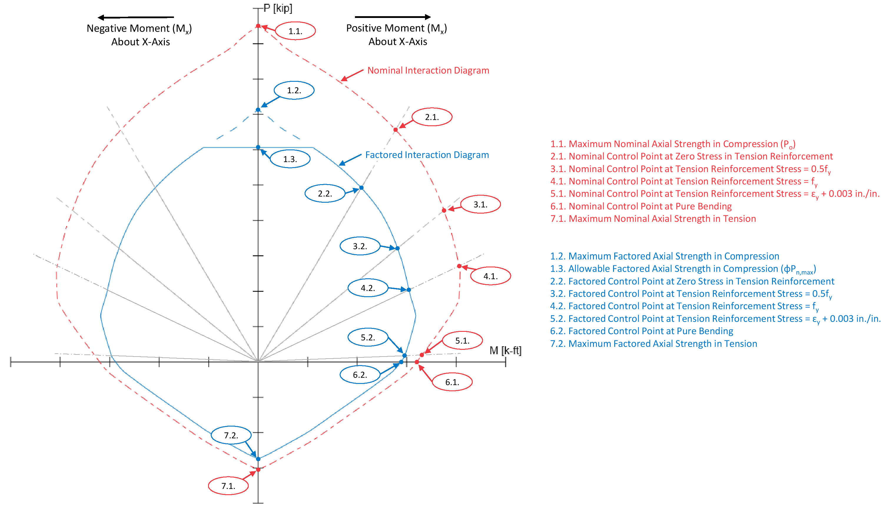
Use the traditional hand calculations approach to generate the interaction diagram for the concrete column section shown above by determining the following seven control points:
Point 2: Bar stress near tension face equal to zero, (fs = 0)
Point 3: Bar stress near tension face equal to 0.5 fy (fs = 0.5 fy)
Point 4: Bar stress near tension face equal to fy (fs = fy)
Point 5: Bar strain near tension face equal to ɛy + 0.003
Several terms are used to facilitate the following calculations:
Figure 2- Circular Column Section Interaction Diagram Control Points

