Building Code Requirements for Structural Concrete (ACI 318-11) and Commentary (ACI 318R-11)
Building Code Requirements for Structural Concrete (ACI 318-14) and Commentary (ACI 318R-14)
Building Code Requirements for Structural Concrete (ACI 318-19) and Commentary (ACI 318R-19)
• Notes on ACI 318-11 Building Code Requirements for Structural Concrete, Twelfth Edition, 2013 Portland Cement Association, Example 7.8 (this reference will be referred as “PCA Notes” in the rest of this document)
• spColumn Engineering Software Program Manual v10.00, STRUCTUREPOINT, 2021
• “Biaxial Bending Interaction Diagrams for Square Reinforced Concrete Column Design (ACI 318-19)” Design Example, STRUCTUREPOINT, 2022
• “Biaxial Bending Interaction Diagrams for Rectangular Reinforced Concrete Column Design (ACI 318-19)” Design Example, STRUCTUREPOINT, 2022
• “Biaxial Bending Interaction Diagrams for C-Shaped Concrete Core Wall Design (ACI 318-19)” Design Example, STRUCTUREPOINT, 2022
• “Biaxial Bending Interaction Diagrams for Spiral Reinforced Circular Concrete Column Design (ACI 318-19)” Design Example, STRUCTUREPOINT, 2022
• Pannell, F. N., “The Design of Biaxially Loaded Columns by Ultimate Load Methods,” Magazine of Concrete Research, London, July 1960, pp. 103-104.
• Pannell, F. N., “Failure Surfaces for Members in Compression and Biaxial Bending,” ACI Journal, Proceedings Vol. 60, January 1963, pp. 129-140.
• Bresler, Boris, “Design Criteria for Reinforced Columns under Axial Load and Biaxial Bending,” ACI Journal, Proceedings Vol. 57, November 1960, pp. 481-490, discussion pp. 1621-1638.
• Furlong, Richard W., “Ultimate Strength of Square Columns under Biaxially Eccentric Loads,” ACI Journal, Proceedings Vol. 58, March 1961, pp. 1129-1140.
• Meek, J. L., “Ultimate Strength of Columns with Biaxially Eccentric Loads,” ACI Journal, Proceedings Vol., 60, August 1963, pp. 1053-1064.
• Aas-Jakobsen, A., “Biaxial Eccentricities in Ultimate Load Design,” ACI Journal, Proceedings Vol. 61, March 1964, pp. 293-315.
• Ramamurthy, L. N., “Investigation of the Ultimate Strength of Square and Rectangular Columns under Biaxially Eccentric Loads,” Symposium on Reinforced Concrete Columns, American Concrete Institute, Detroit, MI, 1966, pp. 263-298.
• Capacity of Reinforced Rectangular Columns Subject to Biaxial Bending, Publication EB011D, Portland Cement Association, Skokie, IL, 1966.
• Biaxial and Uniaxial Capacity of Rectangular Columns, Publication EB031D, Portland Cement Association, Skokie, IL, 1967.
Column dimensions and reinforcement locations are shown in following "Figure 2 - Reinforced Concrete Column Cross-Section and Reinforcement Locations".
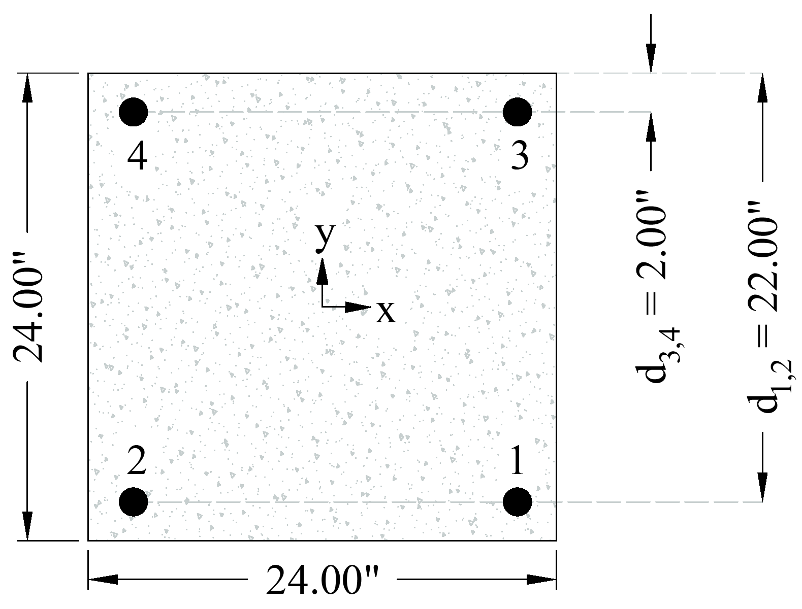
Figure 2 - Reinforced Concrete Column Cross-Section and Reinforcement Locations
Solution - Manual Design Procedure
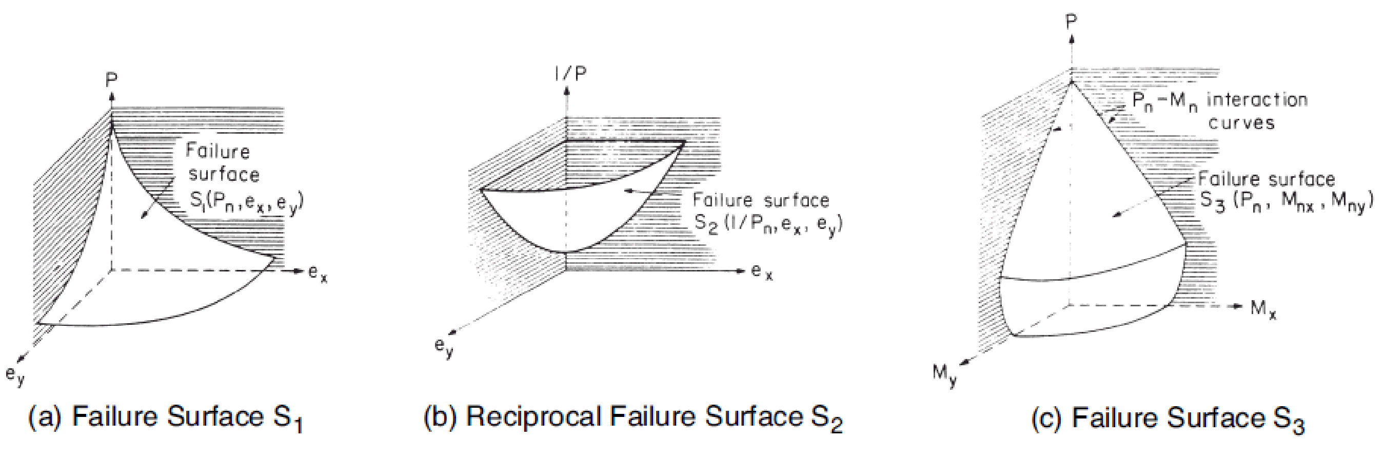
The nominal strength of a section under biaxial bending and compression is a function of three variables Pn, Mnx and Mny which may be expressed in terms of an axial load acting at eccentricities ex = Mny/Pn and ey = Mnx/Pn as shown in "Figure 3 - Notation for Biaxial Loading". A failure surface may be described as a surface produced by plotting the failure load Pn as a function of its eccentricities ex and ey, or of its associated bending moments Mny and Mnx. Three types of failure surfaces have been defined. The basic surface S1 is defined by a function which is dependent upon the variables Pn, ex and ey, as shown in "Figure 4 - Failure Surfaces". a reciprocal surface can be derived from S1 in which the reciprocal of the nominal axial load Pn is employed to produce the surface S2 (1/Pn, ex, ey) as illustrated in "Figure 4 - Failure Surfaces". the third type of failure surface, shown in "Figure 4 - Failure Surfaces", is obtained by relating the nominal axial load Pn to the moments Mnx and Mny to produce surface S3 (Pn, Mnx, Mny). Failure surface S3 is the three-dimensional extension of the uniaxial interaction diagram previously described. A number of investigators have made approximations for both the S2 and S3 failure surfaces for use in design and analysis. An explanation of these methods used in current practice is given below.
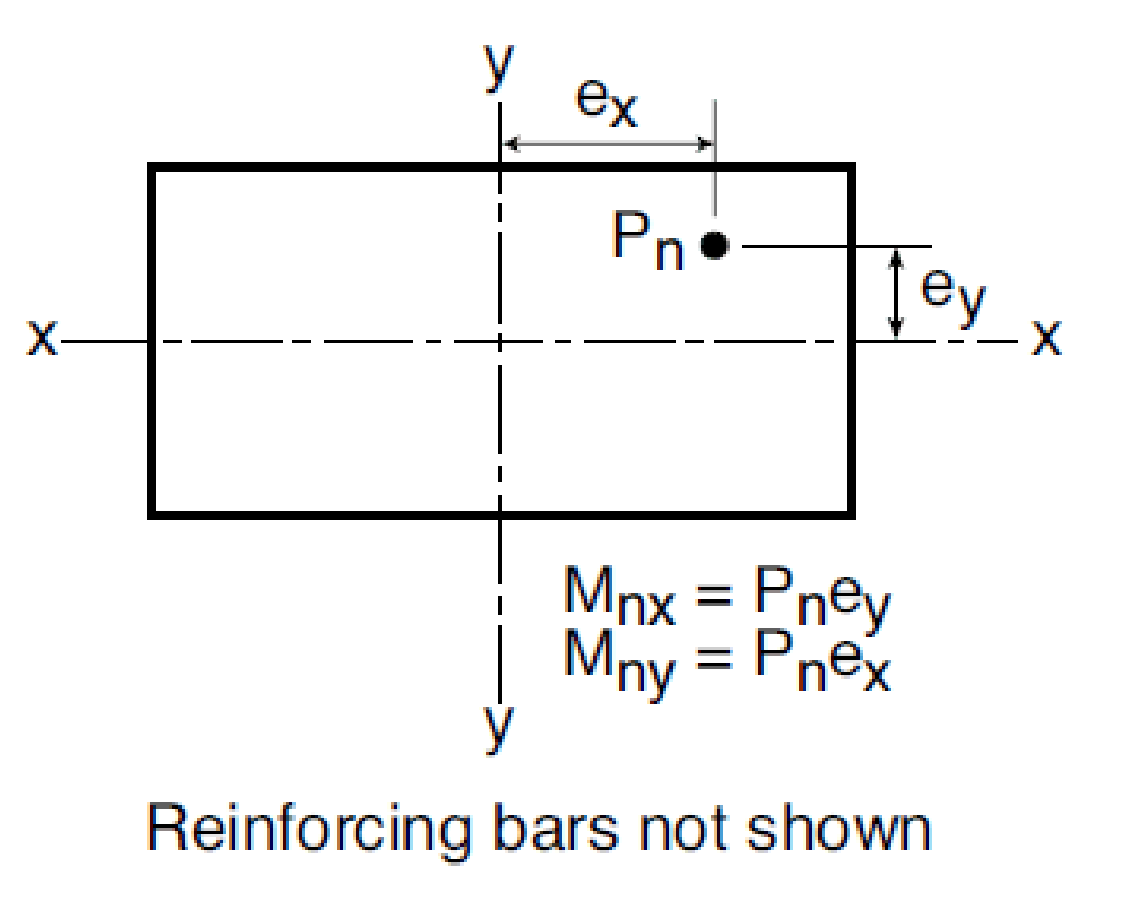
Figure 3 - Notation for Biaxial Loading
The following outlines the approximate manual design procedure proposed by the reference to estimate the capacity of column or wall sections subjected to combined axial load and biaxial bending moments. The procedure is comprised of four key steps where the fourth step covers the approximate biaxial methods.
STEP A) Choose the value of β at 0.65 or use Figures 7-15 and 7-16 in Chapter 7 in PCA Notes to make an estimate.
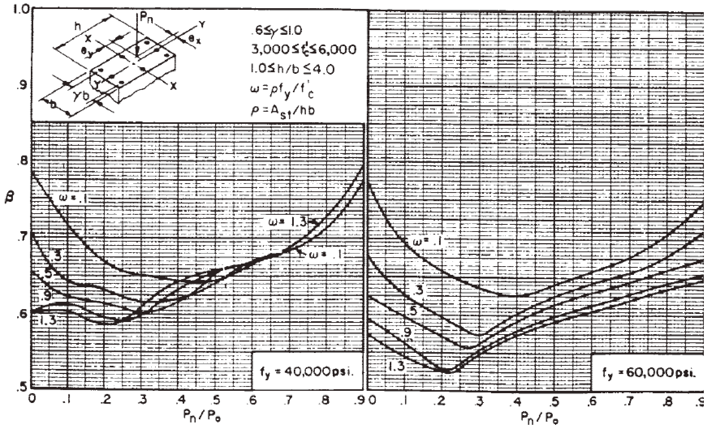
Figure 5 - Sample of Figure 7-15 (Biaxial Design Constants - 4 Bar Arrangement)
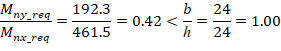
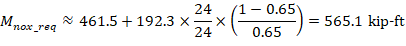
For this example, assume β = 0.65 and compression-controlled behavior

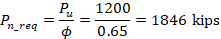
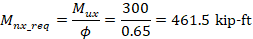
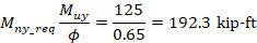
The minimum required strengths equal to:
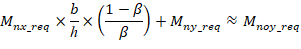
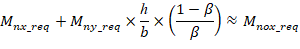
STEP B) If Mny_req/Mnx_req is greater than b/h, use Eq. (17) in Chapter 7 in PCA Notes to calculate an approximate equivalent uniaxial moment strength Mnoy_req. If Mny_req /Mnx_req is less than b/h, use Eq. (20) in Chapter 7 in PCA Notes to calculate an approximate equivalent uniaxial moment strength Mnox_req.
STEP C) Design the section using any suitable approximate or exact method for uniaxial bending with axial load to provide an axial load strength Pn_req and an equivalent uniaxial moment strength Mnoy_req or Mnox_req.
In this example, the exact calculations of column strength for uniaxial bending with axial load is used. Complete details about this procedure is provided in “Interaction Diagram - Tied Reinforced Concrete Column Design Strength (ACI 318-19)” design example. Using the same procedure explained in the design example (Summarized in "Figure 6 - Column Section Capacity Interaction Diagram (spColumn)"), a 24 in. square column with 4 #11 bars provides the following capacities:
Mnox = 682.8 kip-ft > Mnox_req = 565.1 kip-ft
∴ The section is adequate with this reinforcement for (Pn_req, Mnox_req).
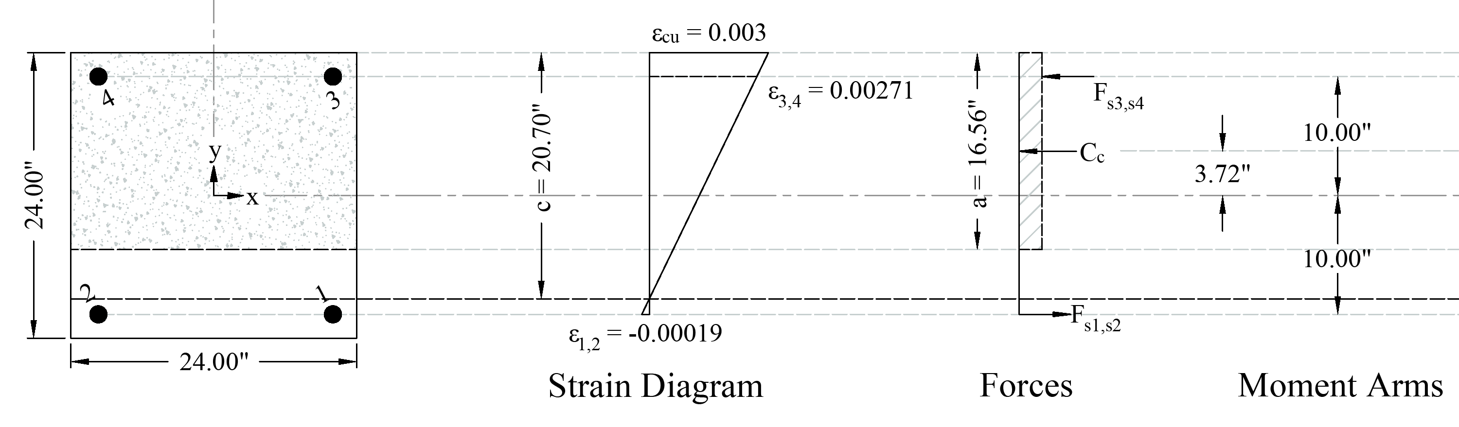
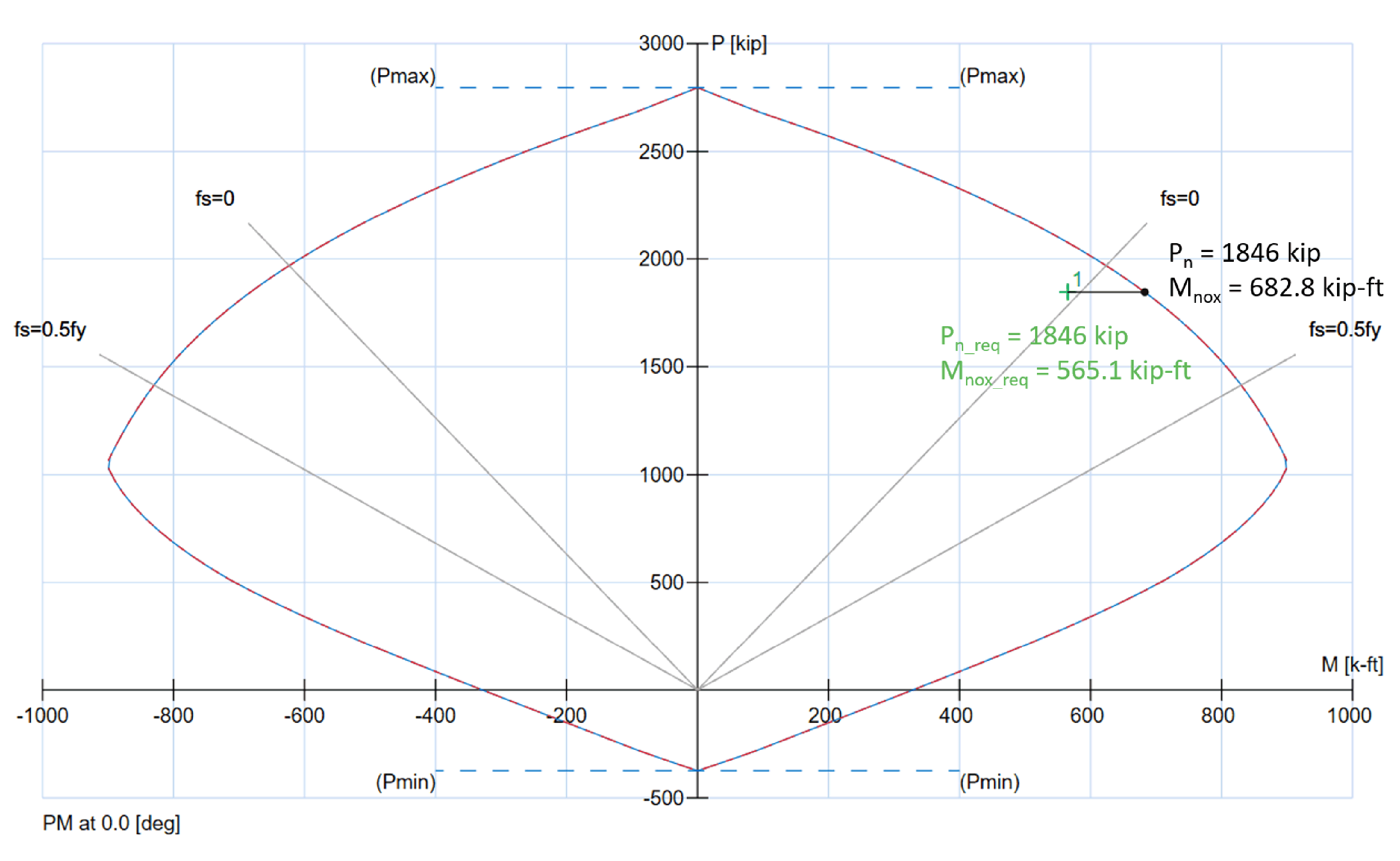
Figure 6 - Column Section Capacity Interaction Diagram (spColumn)
STEP D) Verify the suitability of the chosen section by any one of the following four methods:
1. Bresler Reciprocal Load Method.
2. Bresler Load Contour Method.