Based on the factored axial loads and magnified moments considering slenderness effects, the capacity of the assumed column section (18 in. x 18 in. with 8-#6 bars distributed all sides equal) will be checked and confirmed to finalize the design. A column interaction diagram will be generated using strain compatibility analysis, the detailed procedure to develop column interaction diagram can be found in “Interaction Diagram - Tied Reinforced Concrete Column Design Strength (ACI 318-19)” example.
The axial compression capacity ϕPn for all load combinations will be set equals to Pu, then the moment capacity ϕMn associated to ϕPn will be compared with the magnified applied moment Mu. The design check for load combination #6 is shown below for illustration. The rest of the checks for the other load combinations are shown in the following Table.
Figure 7 - Strains, Forces, and Moment Arms (Load Combination #6)
The following procedure is used to determine the nominal moment capacity by setting the design axial load capacity, ϕPn, equal to the applied axial load, Pu and iterating on the location of the neutral axis.
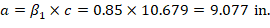
6.1. c, a, and strains in the reinforcement
Where c is the distance from the fiber of maximum compressive strain to the neutral axis. ACI 318-19 (22.2.2.4.2)


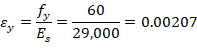


6.2. Forces in the concrete and steel


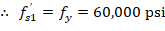


The area of the reinforcement in this layer has been included in the area (ab) used to compute Cc. As a result, it is necessary to subtract 0.85fc’ from fs’ before computing Cs:


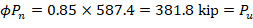
The assumption that c = 10.679 in. is correct.


Therefore, since ϕMn > Mu for all ϕPn = Pu, use 18 x 18 in. column with 8-#6 bars.