The key to successful implementation of spColumn in a project is to understand the unique and powerful approach the program takes in modeling, analyzing, designing, and investigating a structural member subjected to combined axial and flexural loads. This chapter provides an overview of assumptions and considerations the design professional must take into account while utilizing spColumn.
As a general rule, the geometry of the analytical model shall correspond to that of the physical member as closely as possible.
The user shall ensure the project criteria aligns correctly with applicable design code and standard provisions on subjects such as load type, load factors, load combinations, material properties and bar sets to name a few.
4.1.1. Physical Modeling Terminology
A complete model for a structural member requires detailed knowledge of the target structural member and the adjacent framing elements such as:
1. The design column, pier, wall, or beam
2. Structural element above and below the design member
3. Beams and/or slabs framing at the ends of the member in both orthogonal directions
4. Any other constraints at member ends
Refer to Figure 2.3 - Slenderness Input Convention for additional details of input convention and designations.
spColumn allows for designing a new structural member or investigating an existing structural member subject to axial loads with uniaxial or biaxial bending conditions. The components required for successful modeling of structural member is dependent on its slenderness consideration, as follows:
• Slenderness not considered: member can be sufficiently modeled with just the section SHAPE geometry, longitudinal BAR arrangement and their material properties.
• Slenderness considered: member requires, in addition, the height of design member together with the geometric and material properties of columns and beams/slabs at the top and bottom of the design column. This information is essential for slenderness consideration and is key for the determination of magnified moments and their effects on the structural member.
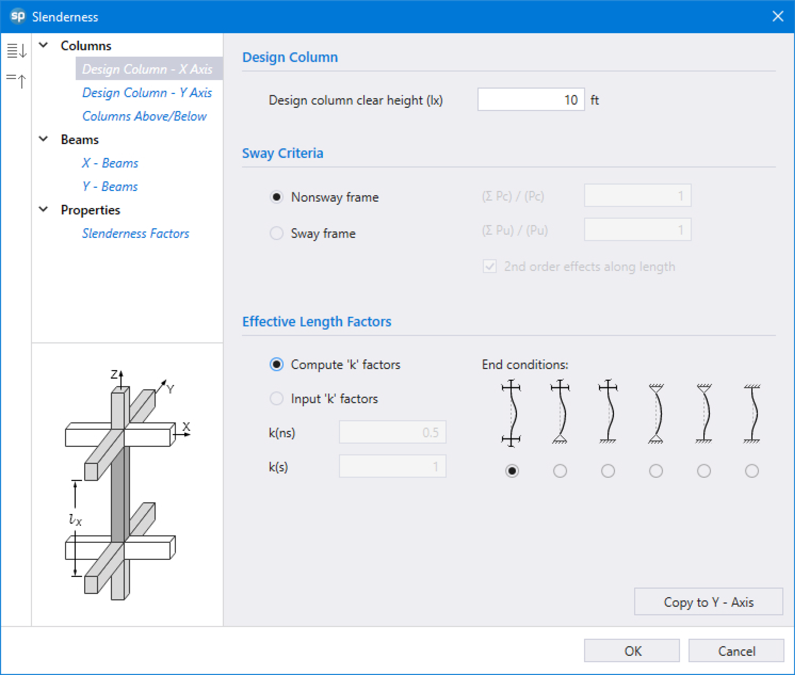
Slenderness can be considered in spColumn by utilizing the Moment Magnification Method (MMM). When slenderness effects are incorporated elsewhere, the Program can be run by selecting NO for CONSIDER SLENDERNESS run option.
When slenderness effects are considered, the height of the design column is considered in addition to the section dimensions. spColumn allows the effective length factor, k, either be inputted by the user or computed based on the end conditions. End conditions options enable the user to enter the member properties at the joint or simply assign it to be predefined pin or fixed conditions.
The section of the target structural member shall be composed of two essential objects, namely: the SHAPE and the REBAR. The modeling objects available to define the section are:
• SHAPE is used to model concrete solids or openings.
• BAR is used to model longitudinal reinforcing bars.
In spColumn, the section can be classified as regular or irregular based on the ability of spColumn to perform design based on user specified limits of shape dimensions and commonly used reinforcing bar patterns. Design of regular sections is an iterative process using an advanced algorithm intended to result in an optimal section with adequate strength for the applied loads. Sections that do not qualify as regular are classified as irregular and can be investigated with many variations of shape and bar arrangements as required by the user.
Regular section is defined as single solid object with standard shape and regular bar arrangement. Regular sections available in the Program with design options are:
• Rectangular is a rectangular solid with rectangular or circular bar layout arranged with all sides equal, equal spacing or sides different.
• Circular is a circular solid with rectangular or circular bar layouts arranged with equal spacing.
Design of regular sections is accompanied with a design trace feature allowing the user the follow the progression of design iteration leading to the final proposed design section.
Irregular section refers to any representation of single solid or multi-solid section that does not fit the description of a regular section. In other words, it cannot be designed using the standard shapes and bar patterns in the design option. Some of the more common irregular sections are shown as follows:
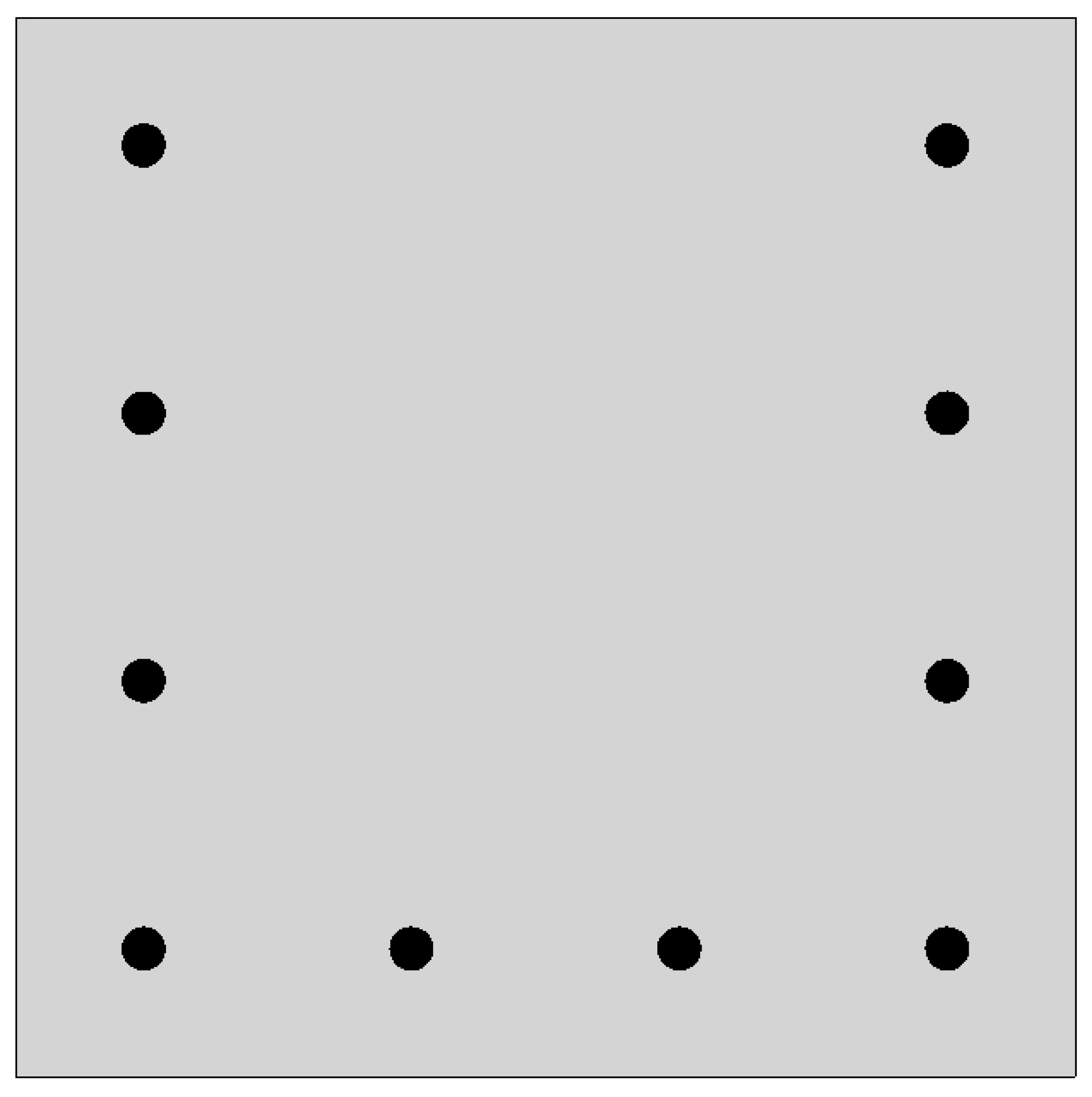
• Regular solid shape with irregular bar arrangement
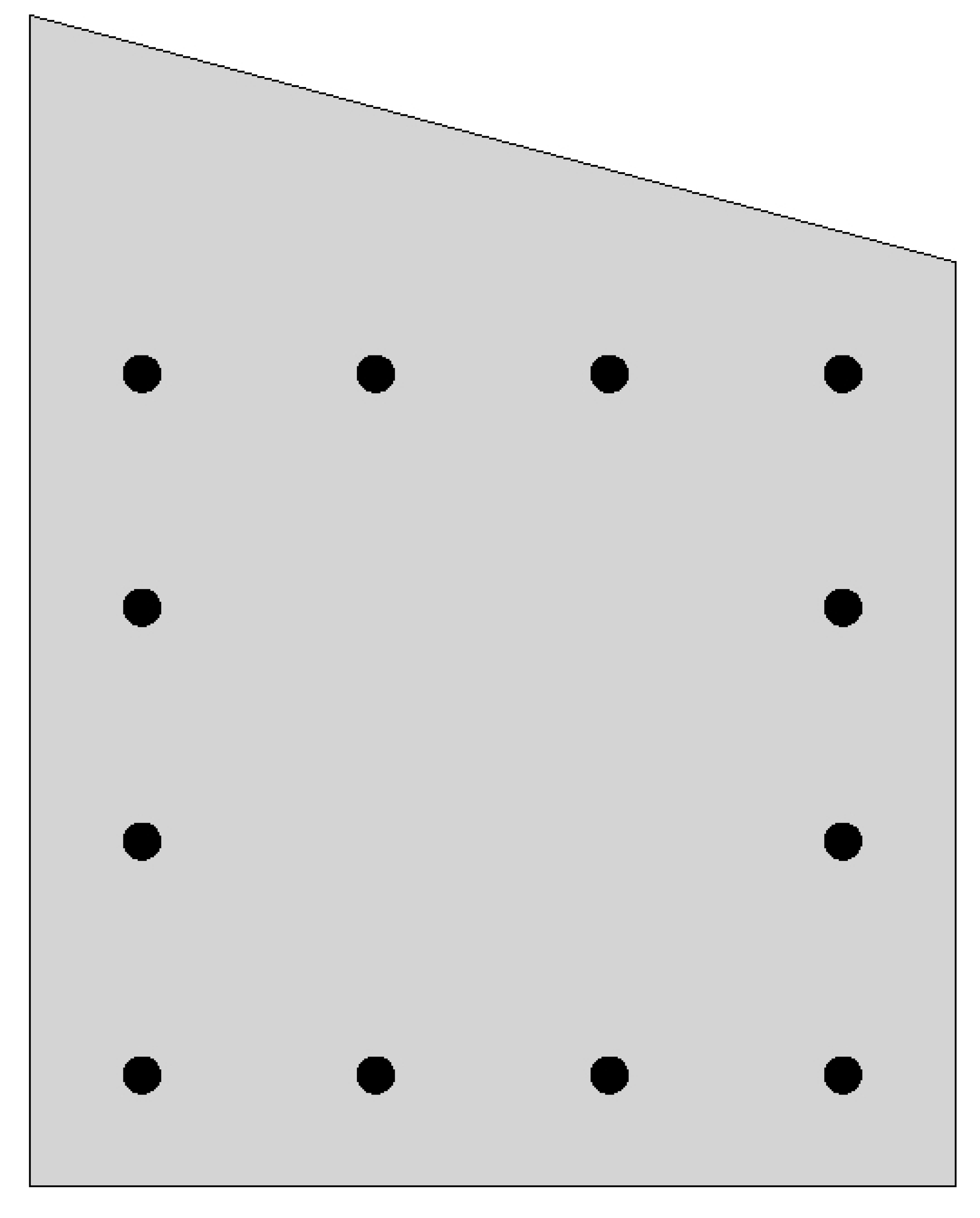
• Irregular solid shape or multiple shapes with regular bar arrangement
• Irregular solid shape or multiple shapes with irregular bar arrangement

• Solid shape with an interior opening
• Solid shape with an exterior opening
• Section created by advance modeling in spColumn or imported via text or DXF input
• Sections created using spColumn pre-selected templates
It is the user responsibility to ensure that the program assumptions and relevant code provisions hold true when modeling any irregular sections.
It is extremely important that all the concepts, assumptions and definitions are understood in order for the analytical model to achieve compliance with supporting provisions permitted by the applicable codes and standards used. It is also essential for the proper interpretation of design and analysis results.
In each model the run option of design or investigation depending is selected by the user based on project needs. The STRENGTH properties of concrete and reinforcing steel are input by the user for modeling the structural member and other members at end conditions. Other material properties are normally calculated per the code standard unless the user elects non-standard manual input.
The BAR SET can be selected as pre-defined sets per American and Canadian standards or the user can create user-defined set for other international design standards or to mimic the area of a bundled bar.
Model input requires a choice of run axis. The BIAXIAL bending consideration constitutes the most comprehensive state that enables the creation of the 3D failure surface and therefore, may be utilized by the user as a default condition in any model. The Uniaxial run option concerns either with ABOUT X-AXIS or ABOUT Y-AXIS runs. If a section does not undergo biaxial bending, the utilization of uniaxial option results in simpler output and fewer input requirements.
The axial load only condition may occur if the bending is negligible. A common case of this is interior column where unbalanced bending moments are negligible. Edge columns may be modeled for axial load with uniaxial bending. Corner columns often require to be modeled for axial load with biaxial bending.
4.1.5. Modeling Considerations
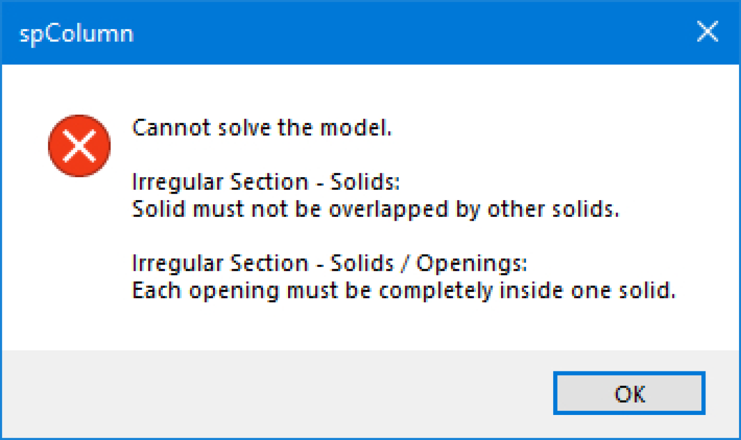
The following set of conditions need to be met for spColumn to proceed with a model solution, otherwise, the program shall provide an error message and the user shall resolve them:
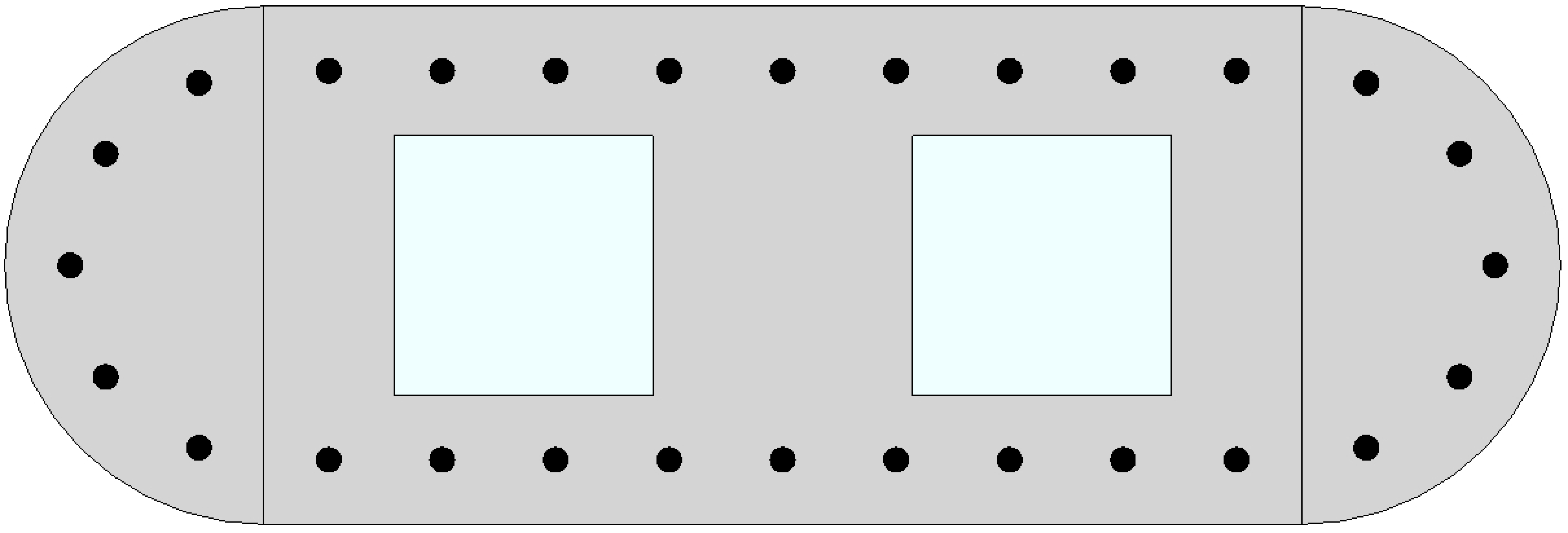
- Each opening shape shall be entirely within a solid shape.
- Solid shapes should not overlap.
- Opening shapes should not overlap.
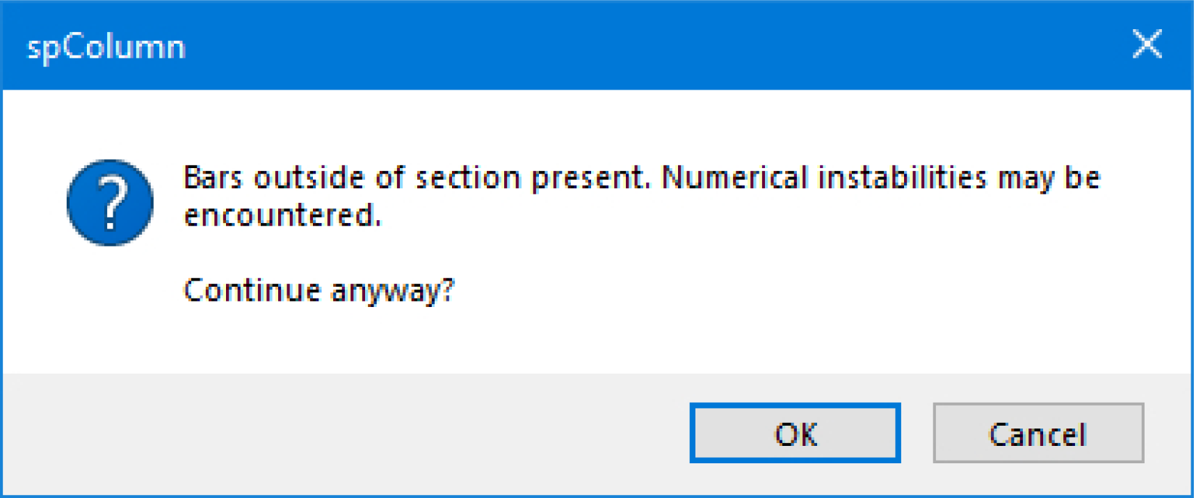
For the following second set of conditions, if any is not met spColumn shall provide a warning message and require user’s permission to proceed:
- The rebar shall need to be placed inside the section.
- The rebar shall not overlap with another rebar.
- Reinforcement ratio shall need to be in between the accepted range for columns 1% - 8%. Where reinforcement ration falls below 1% the program will provide the user with a choice between Architectural and Structural column. An article outlines the background of this choice
Columns with Low Reinforcement - Architectural Columns
Models not meeting these conditions may be for academic and research purposes to investigate transformed cracked sections and other theoretical circumstances. StructurePoint does not support the utilization of spColumn and its results for these models, due to numerical instabilities during analysis run.