2.3. Analysis Methods
2.3.1. Overview of Finite Element Method (FEM) of Analysis
As introduced in Section 2.1., the finite element method is used in spWall for structural analysis of walls. During analysis, spWall converts the object-based model into a finite element model. The user defines the mesh used in the finite element analysis by inputting maximum allowed mesh size and maximum allowed aspect ratio. Additional meshing is automatically introduced at plate boundaries, stiffeners, and nodes with assigned properties such as restraints and point loads.
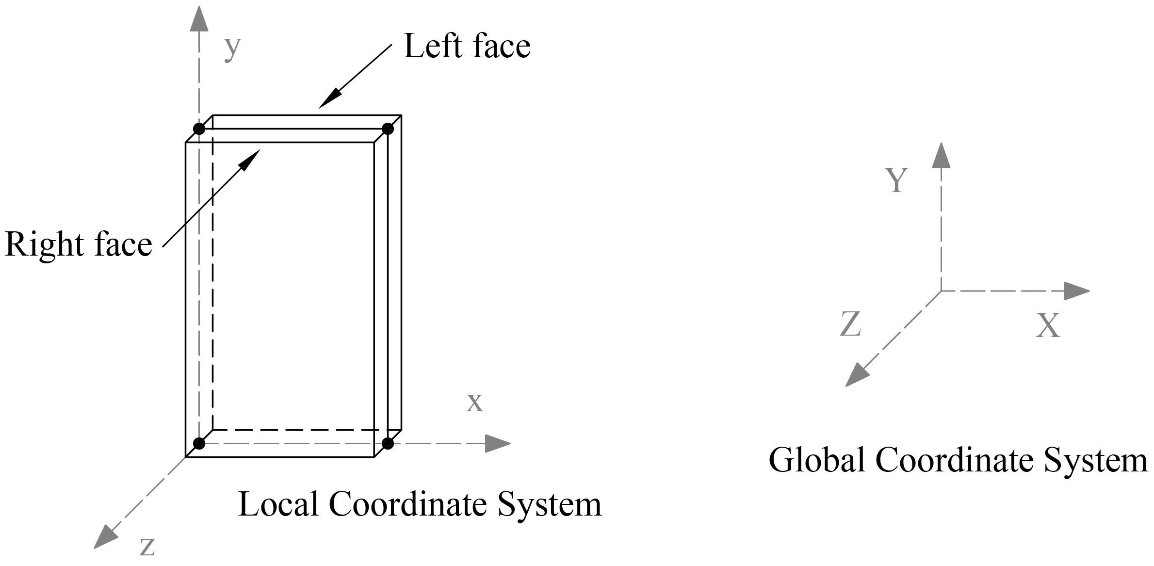
The rectangular plate finite element has four nodes, one at each corner, as shown in "Figure 2.2 - Plate Element". Each node has six degrees of freedom (Dx, Dy, Dz, Rx, Ry, and Rz). The rotation, Rz, is referred to as the drilling rotation4.
The plate element combines the membrane (in plane) and bending (out of plane) actions. Element stiffness is calculated based on the following assumptions
1. The x-y plane is the mid surface of the plate element.
2. Deformations are small and the resulting displacements do not significantly change the geometry of the wall.
3. The membrane and bending deformations are uncoupled.
4. Bending behavior follows the thin plate theory (Kirchhoff theory).
5. Plane sections initially normal to the mid-surface remain plane and normal to that surface after bending.
6. The stress component normal to the mid-plane is small compared to other stress components and is neglected.
7. The plate element material is homogeneous, elastic, isotropic, and obeys Hooke’s law.
If second order analysis is requested, the stiffness terms related to the bending action are modified to include the effect of in-plane internal forces5.
When locating reinforcement within a plate element, the program refers to the left face and right face. The left face of the panel is defined as the face to the left of the plate centerline when looking along the positive X-axis. See "Figure 2.2 - Plate Element".
Stiffener elements can be used to model beams or columns that are embedded in the wall to increase its structural capacity, e.g. lintels, pilasters, and boundary elements of shear walls. Wall piers that are required to be designed as columns can also be modeled using stiffeners.
Additionally, isolated stiffener elements placed outside of the wall can model rigid frame structures attached to the wall. The program will calculate internal forces in the stiffener elements and calculate the area of reinforcement required for axial action combined with biaxial bending as well as shear and torsion.
The stiffener element used in the program has two nodes, one at each end, as shown in "Figure 2.3 - Stiffener Element". Each node has six degrees of freedom (Dx, Dy, Dz, Rx, Ry, and Rz). Element stiffness is calculated based on the following assumptions:
1. The local x-axis passes through the element centroid.
2. Deformations are small and the resulting displacements do not significantly change the geometry of the wall.
3. Axial and bending deformations are uncoupled.
4. Plane sections initially normal to the element axis remain plane and normal to that axis after bending.
5. The stiffener element material is homogeneous, elastic, isotropic, and obeys Hooke’s law.
If second order analysis is requested, the stiffness terms related to the bending about the y-axis are modified to include the effect of the axial force6.
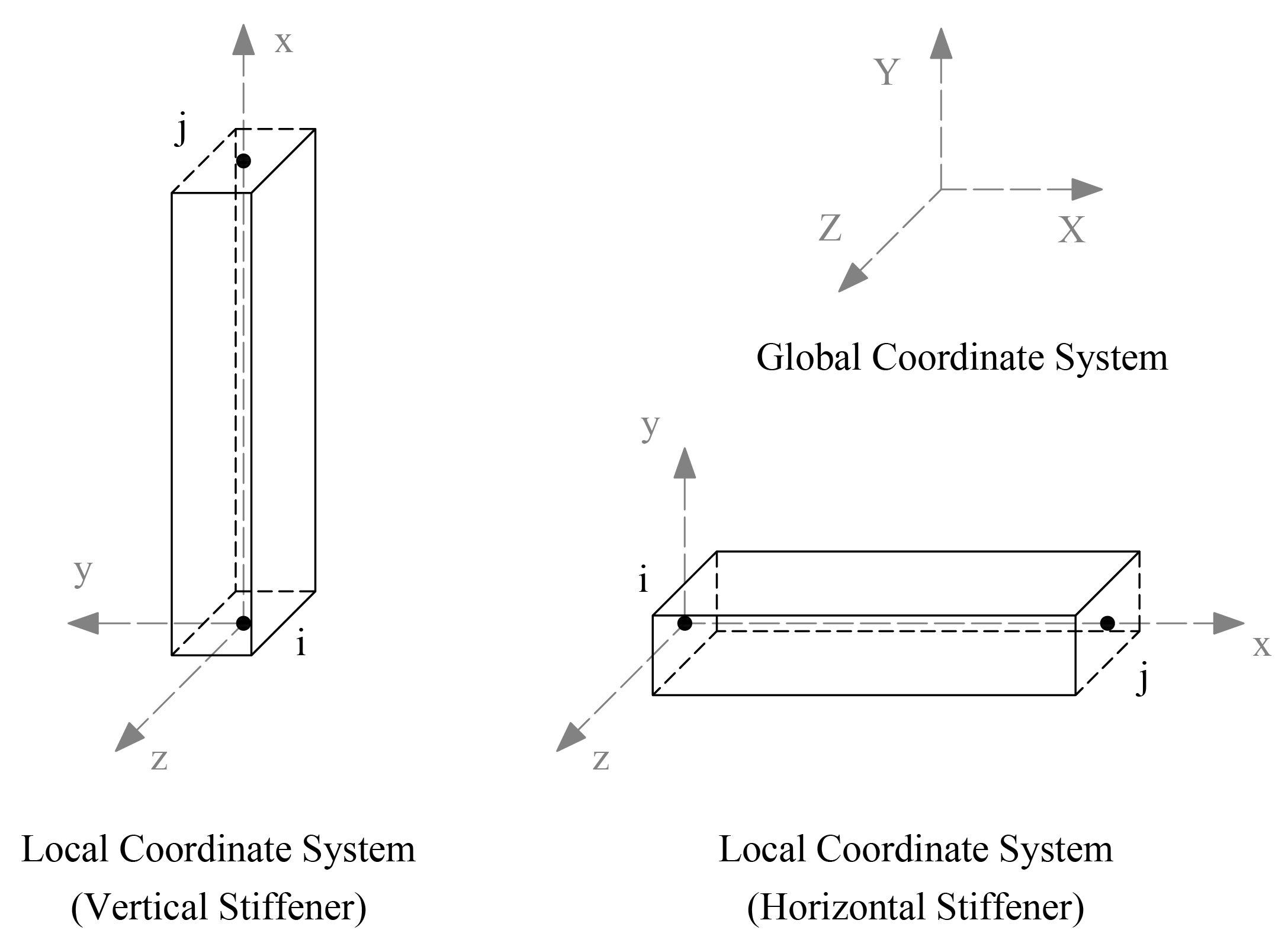
Figure 2.3 - Stiffener Element
The properties of the stiffener section, area (A), Inertia (Iy, Iz) and torsional constant (J) are calculated as follows
Iy = Inertia of the web and the flanges about the centroidal local y-axis.


"Figure 2.4 - Wall Elevation and Sections" shows the elevation and views of a sample wall.
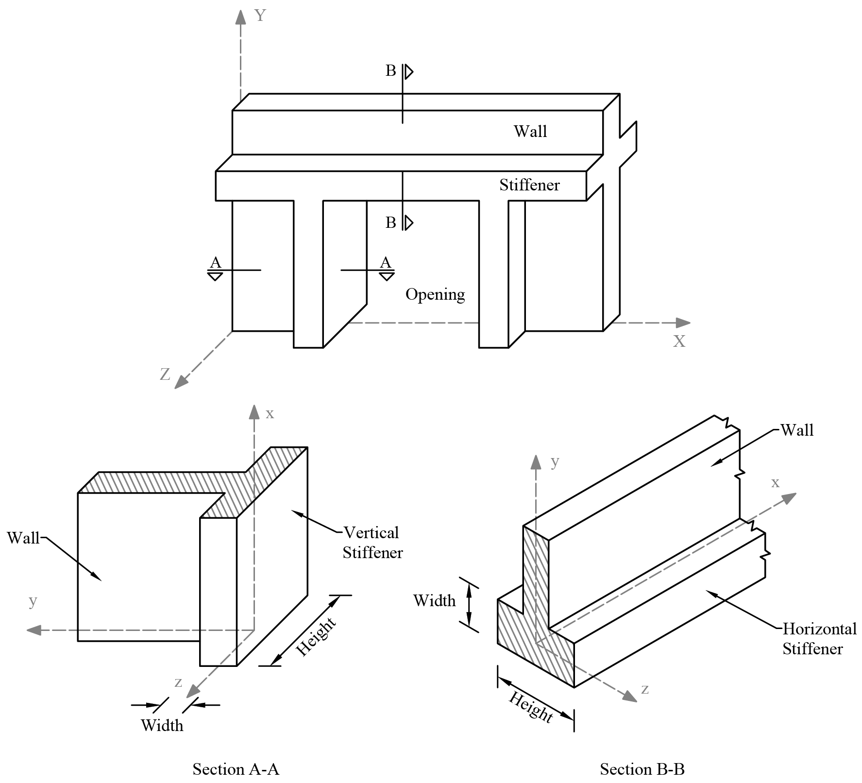
Figure 2.4 - Wall Elevation and Sections
2.3.2. Modeling of Supports
All nodal degrees-of-freedom (DOF) are assumed to be initially released (i.e. free to move). Mathematically speaking, each DOF implies an equilibrium equation; however, nodal DOF may be fully restrained against displacement and/or rotation. This allows the definition of wall supports. For equilibrium to exist, the wall must be restrained such that structure stability is achieved.
Nodal DOF can be partially restrained by defining spring supports. Spring constants corresponding to the six DOF can be defined at any node. The spring supports are idealized as linear springs. Units of the spring constant are in terms of force per unit length for translational springs and moment per radian for rotational springs.
An external load is applied as a point load, a line load, or an area load. Positive forces are defined as forces in the positive direction of the global axes, and positive moments are defined in accordance with the right-hand rule. In other words, if the thumb of your right-hand points in the positive direction of an axis, curling the rest of your right-hand fingers defines the positive moment about that axis.
A point load consists of three forces Px, Py, and Pz and three moments Mx, My, and Mz corresponding to the six DOF at each node. Point forces have units of force, and point moments have units of force times length. Point forces and point moments must be applied at a node. In addition to point moments, an eccentricity in the Z-direction, Ez, can be input. Px and Py values are multiplied by Ez to obtain additional point moments ("Figure 2.5 - Eccentric Point Load"). Thus, the final moments at a node are
 and
and  ,
,
where and are the moment input by the user about the X and the Y axes respectively.
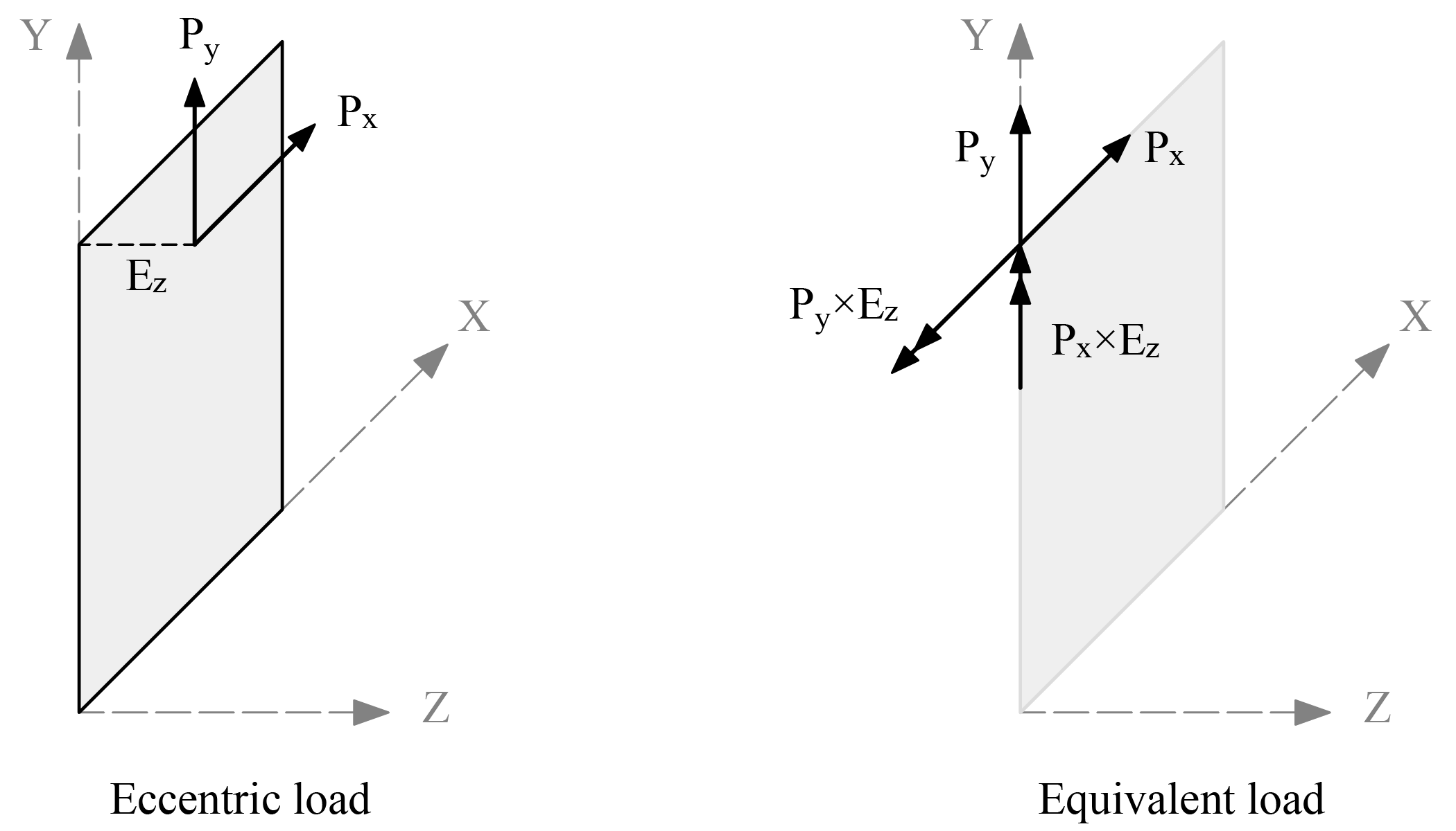
Figure 2.5 - Eccentric Point Load
Eccentricity of the load can also account for wall’s deviation from plumb that is either measured or assumed based for example on specifications for tolerances7.
A line load consists of three uniformly distributed line loads Wx, Wy, and Wz corresponding to the three translational DOF at each node and an eccentricity in the Z-direction, Ez. Line loads must be applied along the boundary of a plate element or along a stiffener element. Wx, Wy, and Wz have units of force per unit length. Internally in the program, lumped-nodal loads replace the line load as follows ("Figure 2.6 - Line Load").
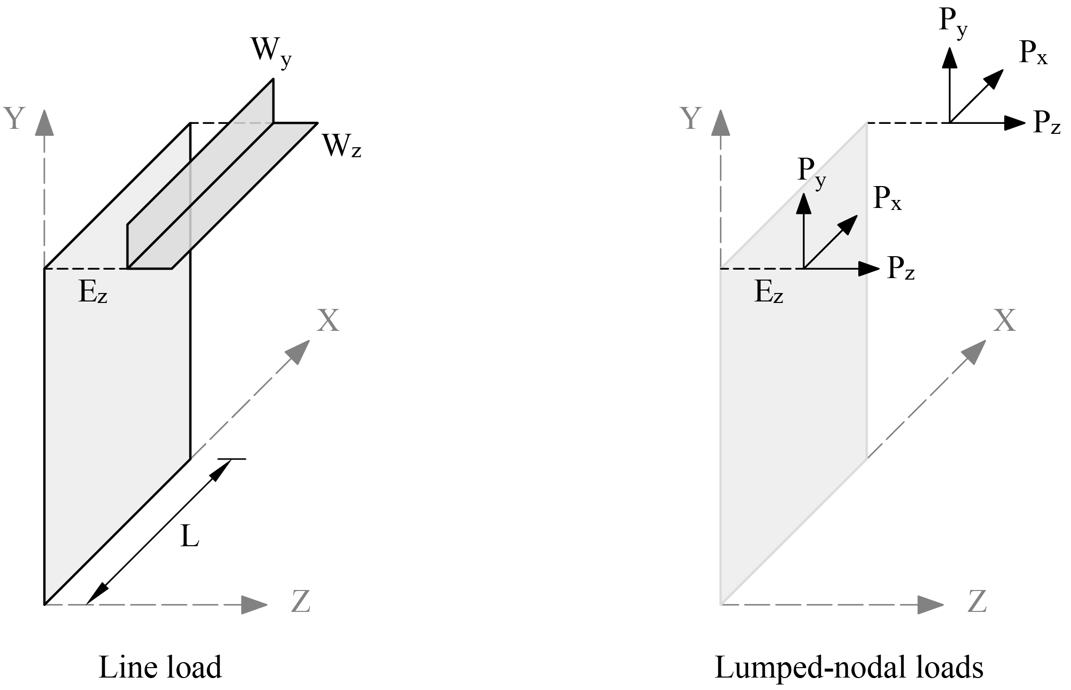
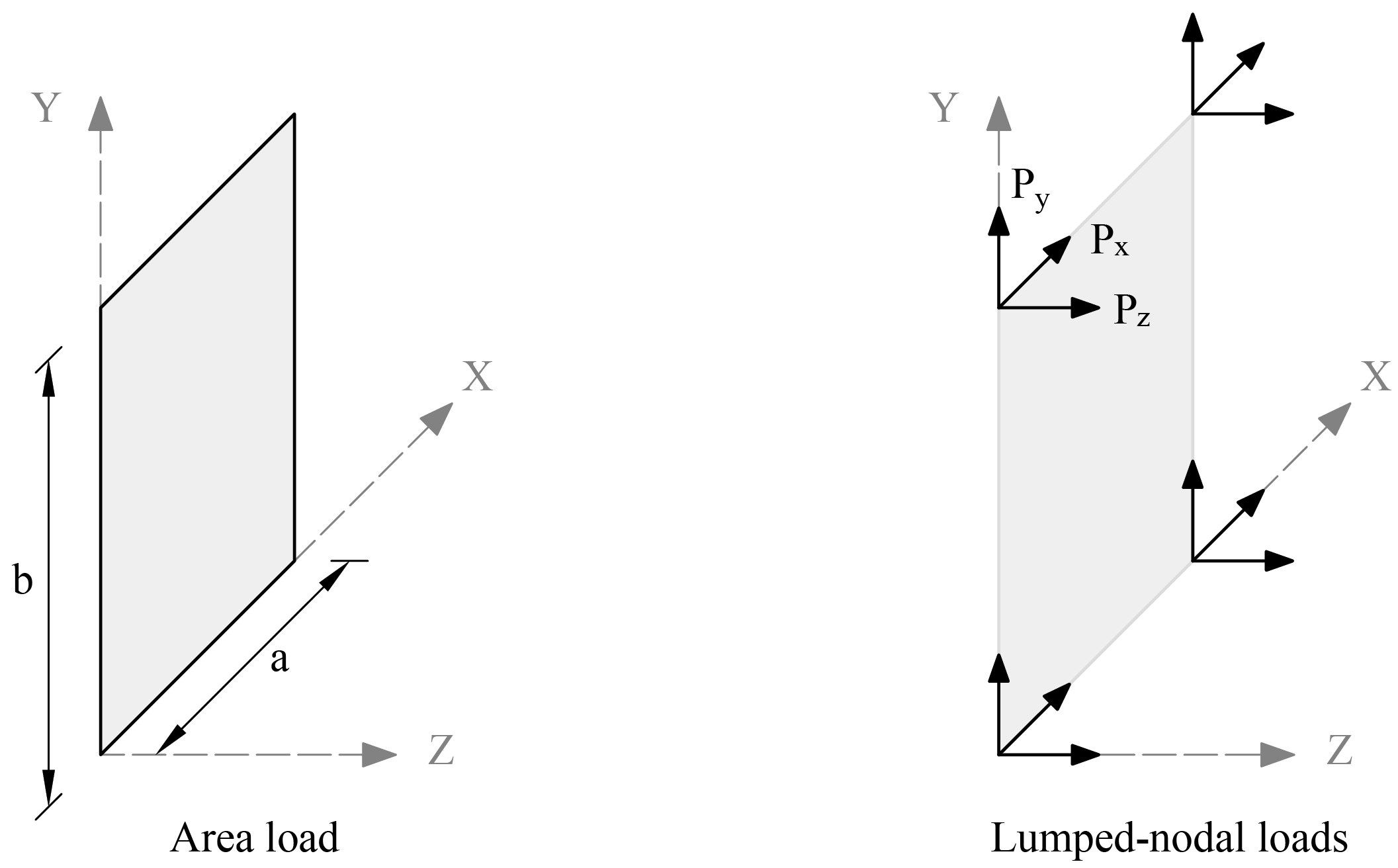
A uniform area load consists of three uniformly distributed loads, Wx, Wy and Wz corresponding to the three translational DOF. Area loads are applied over the area of plate elements. Wx, Wy and Wz have units of force per unit area. Internally in the program, lumped-nodal loads replace the uniform area load as follows ("Figure 2.7 - Area Load").
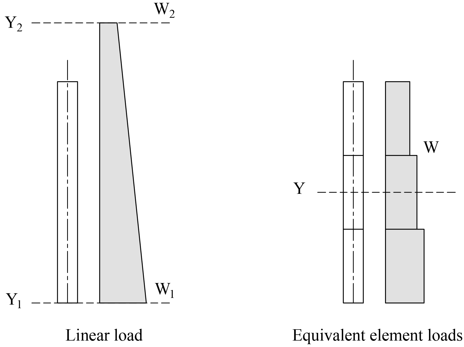
Linear area loads are used to represent water and earth pressure. The load is defined as linearly varying in the Y direction and uniform in the X direction ("Figure 2.8 - Linear Area Load"). The load values are defined at two points, along the Y-direction, whose Y-coordinates are denoted Y1 and Y2 respectively. The load values are denoted Wx1, Wy1, and Wz1 at Y1 while they are denoted Wx2, Wy2, and Wz2 at Y2.
The load is applied to an element as uniform area load intensity of which is calculated as follows:
Where Y is the Y-coordinate of the element center.
The self-weight of the wall is computed internally based on the concrete unit weight and the thickness of each plate element or volume of each stiffener element. For plate elements, the value of self-weight is applied as a uniform area load in the Y-direction. For stiffener element, the value of self-weight is applied as a uniform line load in the Y-direction. The self-weight may optionally be included in the analysis in load case A.
2.3.4. Displacement and Stability - Cracking Coefficients
To account for cracking of elements, the user can input cracking coefficient values for plate and stiffener elements to effectively reduce stiffness. Cracking coefficients for out-of-plane (bending and torsion) and in-plane (axial and shear) stiffness can be entered for plate elements. Cracking coefficients for A, Iz, Iy, and J can be entered for stiffeners. Because the values of the cracking coefficients can have a large effect on the analysis and design results, the user must take care in selecting values that best represent the state of cracking at the particular loading stage. Cracking coefficients are greater than 0 and less than or equal to 1.
At ultimate loads, a wall is normally in a highly cracked state. The user could enter a value for out-of-plane cracking coefficient for plates and Iz and Iy cracking coefficients for stiffeners of Icracked / Igross based on estimated values of As. With an assumed value of As, Icracked can be calculated using the following formula8.

where
Refer to Section 2.6.1. for additional information
After the analysis and design, if the computed value of As greatly differs from the estimated value of As, the analysis should be performed again with new values for the crack coefficients9.
At service loads, a wall may or may not be in a highly cracked state. For service load deflection analysis, a problem should be modeled with an out-of-plane cracking coefficient for plates, and Iz and Iy cracking coefficients for stiffeners of Ieffective / Igross. Ieffective is a value between Icracked and Igross. The value of Ieffective can be obtained from the following formula10.
2.3.5. Analysis Solution and Results
The solution process is summarized in the following steps.
A. Perform in-plane analysis
1. Compute the plate and stiffener element matrices related to the in-plane degrees of freedom (δx, δy, and θz).
2. Assemble the in-plane global stiffness matrix, [Ki].
3. Combine the applied loads and form number of load vectors equal to the number of load combinations, [Fi].
4. Compute the displacement [Ui], by solving the equilibrium equations.
5. Compute the plate element in-plane forces Nxx, Nyy, and Nxy.
6. Compute the stiffener element in-plane end forces Fx, Fy, and Mz.
7. Compute the reaction forces Fx, Fy, and Mz at each restrained node.
B. Perform out-of-plane analysis
1. If first order analysis is requested, the out-of-plane analysis is done once for all load combinations in a similar way to that done for the in-plane analysis.
2. Out-of-plane analysis gives
i. the displacements (δz, θx, and θy) at each node,
ii. the reaction forces Fz, Mx, and My at each restrained node,
iii. the plate element internal moments Mxx, Myy, Mxy,
iv. the stiffener element end forces Fz, Mx, and My.
3. If second order analysis is requested (the default setting), a complete analysis cycle is done for each load combination. In each cycle, the basic stiffness terms of plate elements are modified to account for the effect of membrane forces11. For stiffener elements, the basic stiffness matrix is modified to account for the effect of axial forces12.
C. Compute envelopes for the displacements produced by all service load combinations.
D. For each plate and stiffener element, compute the area of steel required for resisting all ultimate load combinations, For plate elements, the required area of steel is calculated at the element center. For stiffener elements, the area of steel is calculated at each of the element ends. Then, the maximum value of area of steel is reported.
The program output is organized into tables that may be optionally viewed, printed, or sent to file. Furthermore, the tables may be fully or partially output for all or for only selected nodes, members, and load combinations.
Nodal Displacements
Nodal displacements Dx, Dy, and Dz are output for individual service and individual ultimate load combinations. Positive displacement is in the positive direction of the axes. If the user selects the option to check out-of-plane displacement against the maximum permissible value provided by the user, the program will perform the comparison and flag service displacement results where the permissible values are exceeded.
Reactions
Restraint and Nodal Spring reactions are output for individual service load and ultimate load combinations for nodes with specified restraints or nodal springs. Nodal translational reactions Fx, Fy, and Fz, and rotational reactions Mx, My, and Mz are output. Positive translational reactions are in the direction of the positive axes and positive moment reactions are determined using the right-hand rule. The program also reports sum of forces and moments with respect to wall center of gravity for applied loads and reactions.
Element Internal Forces
For each plate element, internal forces Nxx, Nyy, Nxy, Mxx, Myy and Mxy are output for individual service or ultimate load combination.
For each stiffener element, internal forces N, Vy, Vz, My, Mz and Tx are output for individual service or ultimate load combination.
Displacement Envelopes
Maximum nodal displacements Dx, Dy, and Dz from all service load combinations are output. The governing load combination is identified. Positive displacements are in the direction of the positive axes.
Element Reinforcement
For each plate element, the required areas of reinforcement Asx and Asy are computed based on the average moments per element and are output along with design forces and governing ultimate load combination. In both horizontal and vertical directions, the reported reinforcements is the total required area of steel per unit length. Half of the reported value applies to each curtain in models with two curtain layout.
If the area of vertical reinforcement for a plate element is greater than one percent (0.5 percent for CSA A23.3-14/04), the program indicated that ties are required for bars in compression. If the program reports that ties are required for a single curtain design, switching to two curtain design should be considered by the user.
For each stiffener element, the required area of longitudinal reinforcement for flexure and axial loads As, transverse reinforcement, Av/s, required for shear and torsion, and torsional transverse reinforcement At/s and Al are output along with the design forces and governing ultimate load combination. Area of transverse reinforcement required for shear only can be calculated by subtracting twice the torsional reinforcement area from the area required for both shear and torsion.
Wall Cross-Sectional Forces
The program reports values of cross-sectional forces (Nuy, Vux, Vuz, Mux, Muy, Muz) at entire wall sections directly above (+) and directly below (–) each horizontal grid line level. The cross-sectional forces are calculated as sums of all corresponding forces or moments (with respect to cross-section centroid) applied as loads or reactions on one side of the section less forces and moments transferred by stiffeners if the wall section intersects any.
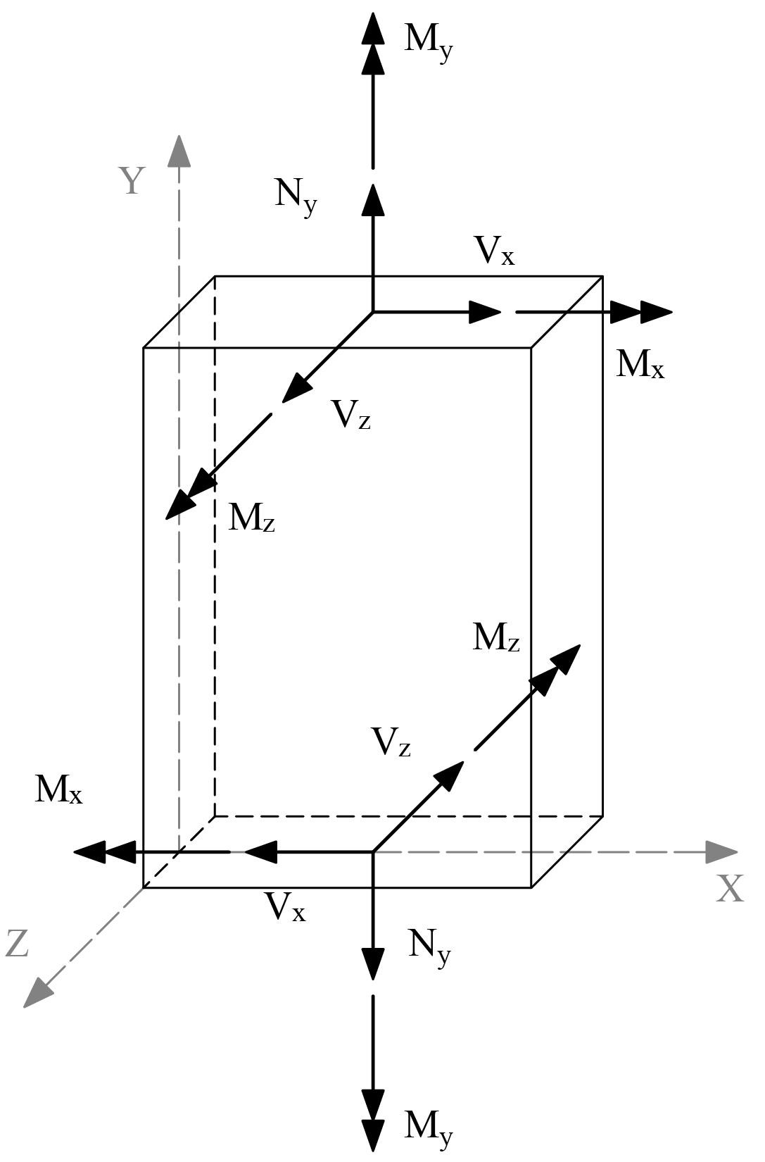
Figure 2.9 - Wall Cross-sectional Forces
The wall cross-sectional forces are used by the program to determine wall shear strength provided by concrete. The user may also use these forces to verify correctness of load input or as input to supplemental calculations of flexural and shear reinforcement for entire wall cross-sections.
Wall Shear Strength
For solid (without openings) walls designed according to the ACI code, the program optionally reports factored in-plane (Vcx) and out-of-plane (Vcz) shear strength provided by concrete in entire wall cross-sections above and below each horizontal grid line level. The shear strengths are also compared to the corresponding calculated shear forces Vux and Vuz, respectively. The comparison may be used by the user to determine the adequacy of the wall thickness and whether additional shear reinforcement or minimum shear reinforcement is required in addition to the axial and flexural reinforcement calculated by the program.