2.1. Introduction
spWall uses the Finite Element Analysis (FEA) Method for the structural modeling and analysis of slender and non-slender reinforced concrete walls subject to static loading conditions.
The wall is idealized as a mesh of rectangular plate elements and straight-line stiffener elements. Walls of irregular geometry are idealized to conform to geometry with rectangular boundaries. Even though plate and stiffener properties can vary between elements, they are assumed uniform within each element.
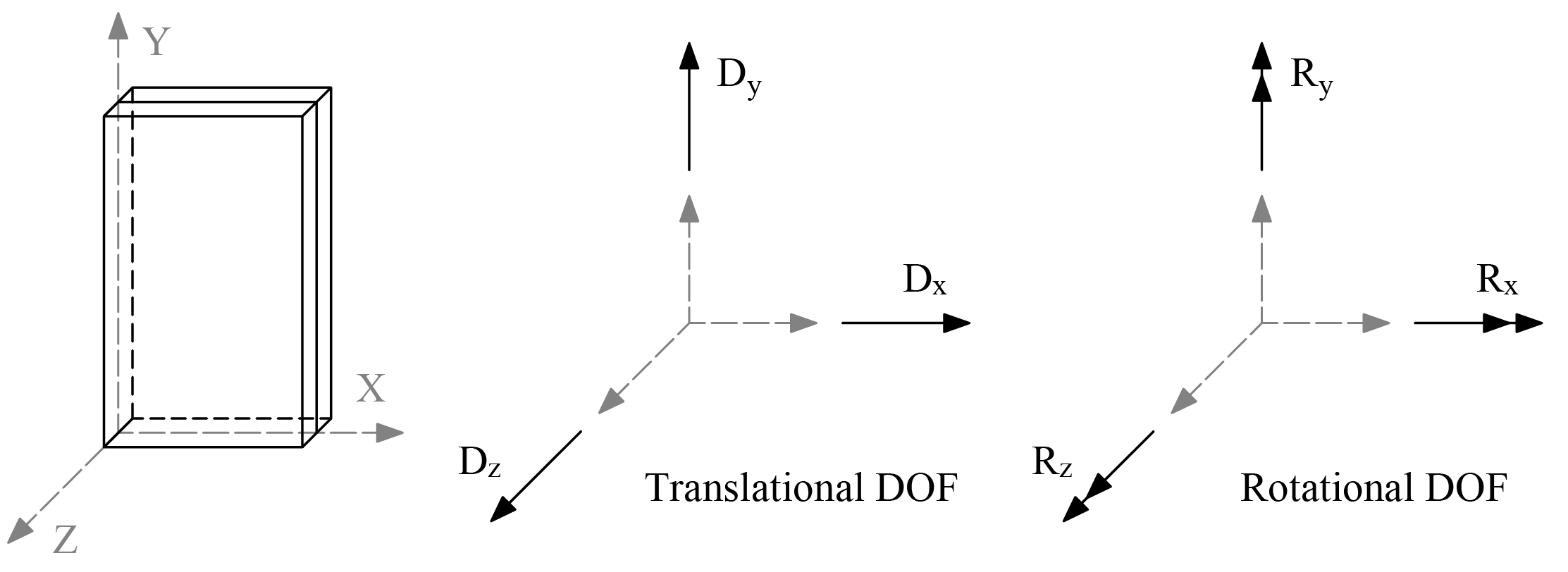
The six degrees of freedom considered at each node are the three translations and three rotations relating to the three Cartesian axes. An external load can exist in the direction of each of the degrees of freedom, i.e., three forces and three moments about the Cartesian axes. Sufficient number of nodal degrees of freedom should be restrained in order to achieve stability of the model.
The program assembles the global stiffness matrix and load vectors for the finite element model. Then, it solves the equilibrium equations to obtain deflections and rotations at each node. Finally, the program calculates the internal forces and internal moments in each element. At the user’s option, the program can perform second order analysis. In this case, the program takes into account the effect of in-plane forces on the out-of-plane deflection.
Walls can be designed using simplified methods such as the empirical design method and alternative method provided in ACI 318 and CSA A23.3 standards1. Such methods are limited to specific wall geometry, section attributes, loading configuration, and support conditions. Walls that do not meet these limitations are required to be designed as compression members2 and slenderness effects in them can be accounted for by performing second-order analysis3. This general approach is implemented in spWall to allow for a wider range of wall configurations and applications.
The program calculates the required amount of reinforcement in the plate elements and stiffener elements based on the code selected by the user. For solid walls, spWall can also compare cross-sectional shear forces with calculated in-plane and out-of-plane shear strength provided by concrete. User can use this information to determine the need for additional shear strength and finalize the reinforcement distribution and detailing.
2.1.1. Wall Systems
spWall can be used to model, analyze, and design wall systems such as shear walls, bearing walls, precast walls, tilt-Up walls, tank walls, retaining walls, and deep beams (also known as transfer girders). Samples of such systems are illustrated below:
Shear Walls | Bearing Walls |
Precast Walls | Tilt Up Walls |
Tanks & Retaining Walls
Deep Beams / Transfer Girders
Global Coordinate System
The mid-surface of the wall lies in the XY plane of the right-handed XYZ rectangular coordinate system shown in "Figure 2.1 - Global Coordinate System". The wall thickness is measured in the direction of the Z-axis. The positive X-axis points to the right, the positive Y-axis points upward towards the top of the monitor, and positive Z-axis points out of the screen. Thus, the XY plane is defined as being in the plane of the display monitor.

Figure 2.1 - Global Coordinate System
While the local and global coordinate systems are the same for plate elements and horizontal stiffeners, the vertical stiffeners local coordinate system is different from the global. Refer to "Figure 2.2 - Plate Element" and "Figure 2.3 - Stiffener Element" for more information.