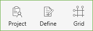
In the Start Screen under Projects select the New Project option. The model development process may require general input regarding a specific project. Project Information is entered through the Project command button, and Structural Grids are entered through the Grid command button.
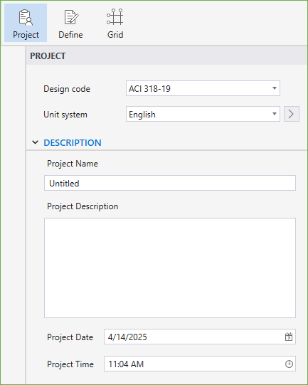
The project information regarding to DESIGN CODE, UNIT SYSTEM, PROJECT NAME, PROJECT DESCRIPTION, PROJECT DATE, and PROJECT TIME can be entered into the model through the Project Left Panel. The Program supports American (ACI 318) and Canadian (CSA A23.3) Design Codes, and English and Metric unit systems.
The structural grids can be created or imported in order to facilitate the input of structural elements such as columns, walls, piles in a specific structural plan view.
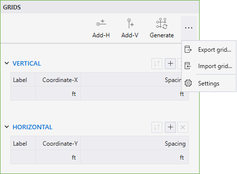
You can select the Grid command button from the Ribbon. The corresponding Grids Left Panel provides various tools and options for effectively working with grids.
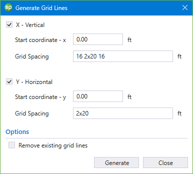
• Click the Generate icon to display the GENERATE GRID LINES dialog box
• To create multiple grid lines at once enter:
number of grid spaces x grid interval in the GRID SPACING input box
• Entering a single number in the GRID SPACING input box will create a single grid line at the given spacing from either the start coordinates or the last existing grid line in that direction
• You can create grid lines at multiple intervals by separating the grid intervals by space
Click the Add-H or Add-V commands to add a single HORIZONTAL or VERTICAL grid.
You can use the Grid table to change the LABEL, COORDINATE or SPACING of the grid. The table can also be used to add or delete specific grids.
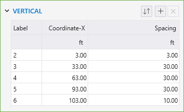
• Click on the  button to add a gridline in the active direction.
• Click on the  button to delete the selected gridline in the table.
• Click on the  button to reorder the labels if they have been shuffled.
• To change a grid LABEL, click on the desired grid in the table and click on its label.
Leaving a grid label field empty will remove the label bubble from the gridline in the model.
• COORDINATE or SPACING of the grids can also be changed by clicking on the respective field and typing in the desired value.
• Changing the coordinate of the first gridline in the table displaces the entire grid system in the respective direction.
• Except the first gridline in the table, other gridlines cannot be assigned a negative spacing value.
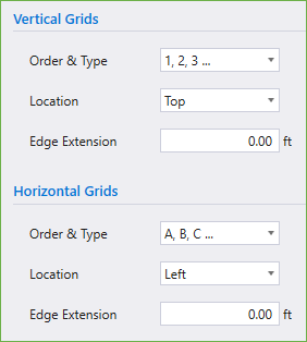
You can use the Settings / General / Grids to change the ORDER & TYPE and LOCATION of the grid labels. You can also change how far the grid labels are located from the grid lines by changing the EDGE EXTENSION value.
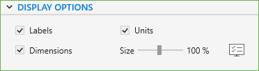
• Use the checkboxes to toggle the display of various grid items in the model.
• You can use the slider to adjust the SIZE of the grid LABELS, UNITS and DIMENSIONS displayed.
Once the project information has been completed, editing and adding new definitions can be done in the DEFINITIONS Dialog Box by selecting the Define command button from the Ribbon.
The DEFINITIONS dialog box contains predefined labels for various Objects, Properties, Restraints, and Load Case/Combo. You can enter additional definitions per your project requirements by clicking the NEW button. Similarly, an existing definition can be removed by clicking the DELETE button. Either start by creating definitions to be used in the program in the DEFINITIONS dialog box or simply start creating the model with one of the several command buttons available in the Ribbon using the default program definitions.
Items like PROPERTIES, RESTRAINTS and LOAD CASES/COMBO are available during modeling only after they have been first defined in the DEFINITIONS dialog box. Objects i.e. slabs, columns and piles can also be defined in the DEFINITIONS dialog box to be used during modeling. Conversely, Object definitions are automatically added to the list of definitions as they are created and used during modeling process.
Clicking the dialog launcher  next to an item in the Left Panel will open the DEFINITIONS dialog box.
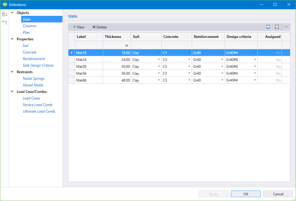
The Objects that can be defined are: Slabs, Columns and Piles.
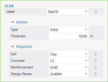
The Slabs Object definition consists of the LABEL, THICKNESS, PROPERTIES, and whether the Slabs label is ASSIGNED in the model or not.
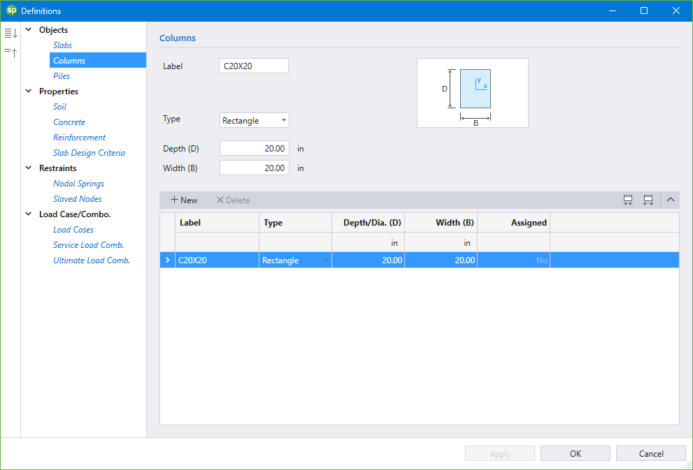
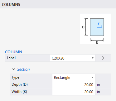
The Columns Object definition consists of the LABEL, TYPE, DIMENSIONS, and whether the Column label is ASSIGNED in the model or not.
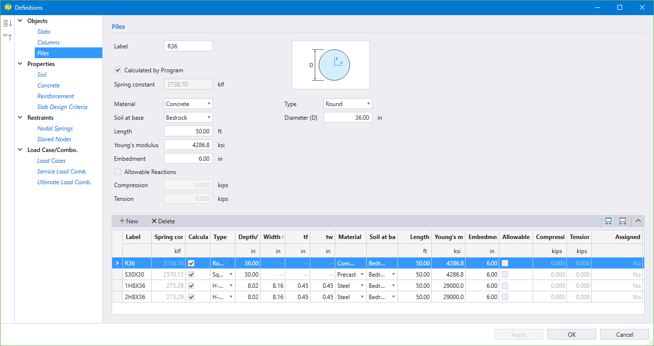
The Piles Object definition consists of the LABEL, TYPE, DIMENSIONS, and CHARACTERISTICS OF PILE, SUPPORTING SOIL, ALLOWABLE REACTIONS, and whether the Pile label is ASSIGNED in the model or not.
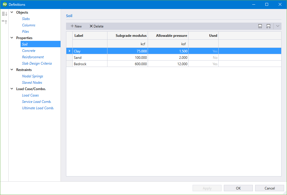
The Properties that can be defined are: Soil, Concrete, Reinforcement, and Slab Design Criteria.
The Soil definition consists of the LABEL, SUBGRADE MODULUS, ALLOWABLE PRESSURE, and whether the Soil label is USED in the model or not.
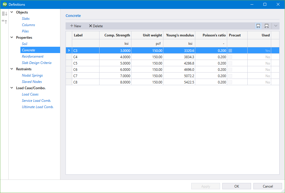
The Concrete definition consists of the LABEL, COMPRESSIVE STRENGTH, UNIT WEIGHT, YOUNG’S MODULUS, POISSON’S RATIO, and whether the Concrete label is USED in the model or not.
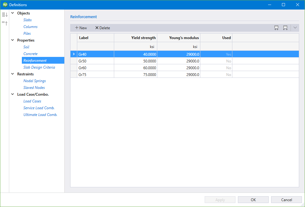
The Reinforcement definition consists of the LABEL, YIELD STRENGTH, YOUNG’S MODULUS, and whether the Reinforcement label is USED in the model or not.
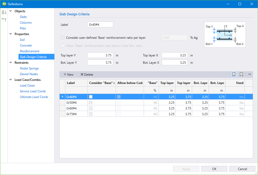
The Slab Design Criteria definition consists of the LABEL, CONSIDER USER-DEFINED BASE REINFORCEMENT RATIO PER LAYER, ALLOW BASE REINFORCEMENT RATIO BELOW CODE MIN. RATIO, REINFORCEMENT CENTERLINE LOCATIONS, and whether the Slab Design Criteria label is USED in the model or not.
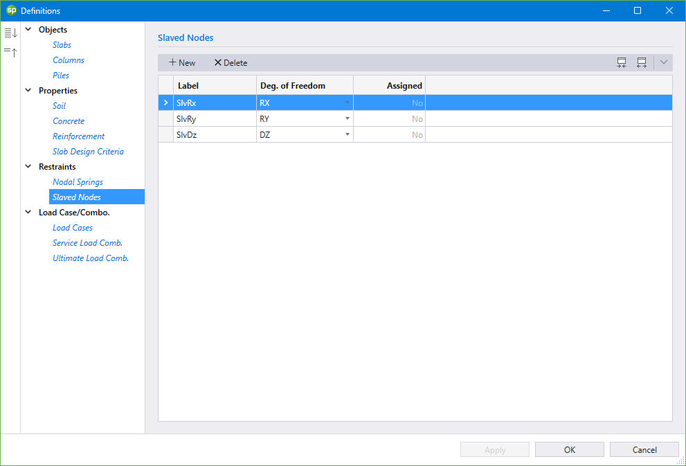
The Restraints that can be defined are: Nodal Springs, and Slaved Nodes.
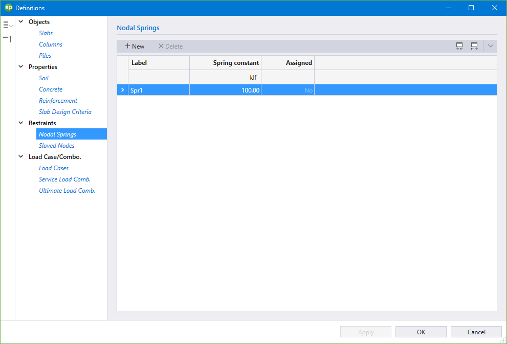
The Nodal Springs definition consists of the LABEL, SPRING CONSTANT, and whether the Nodal Spring label is ASSIGNED in the model or not.
The Slaved Nodes definition consists of the LABEL, DEGREE OF FREEDOM, and whether the Slaved Node label is ASSIGNED in the model or not.
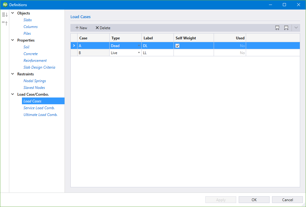
The Load Case / Combo. that can be defined are: Load Cases, Service Load Combinations, and Ultimate Load Combinations.
The Load Cases definition consists of the CASE, TYPE, LABEL, whether the SELF-WEIGHT be included with the load case or not, and whether the Load Case is USED in the model or not.
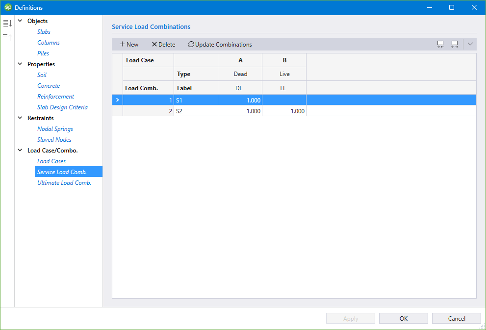
The Service Load Combinations definition consists of the LOAD CASES, LOAD CASE TYPE, LOAD COMBINATION NUMBER, LOAD COMBINATION LABEL, and LOAD FACTORS. Load combinations can also be generated automatically based on the design code in the model.
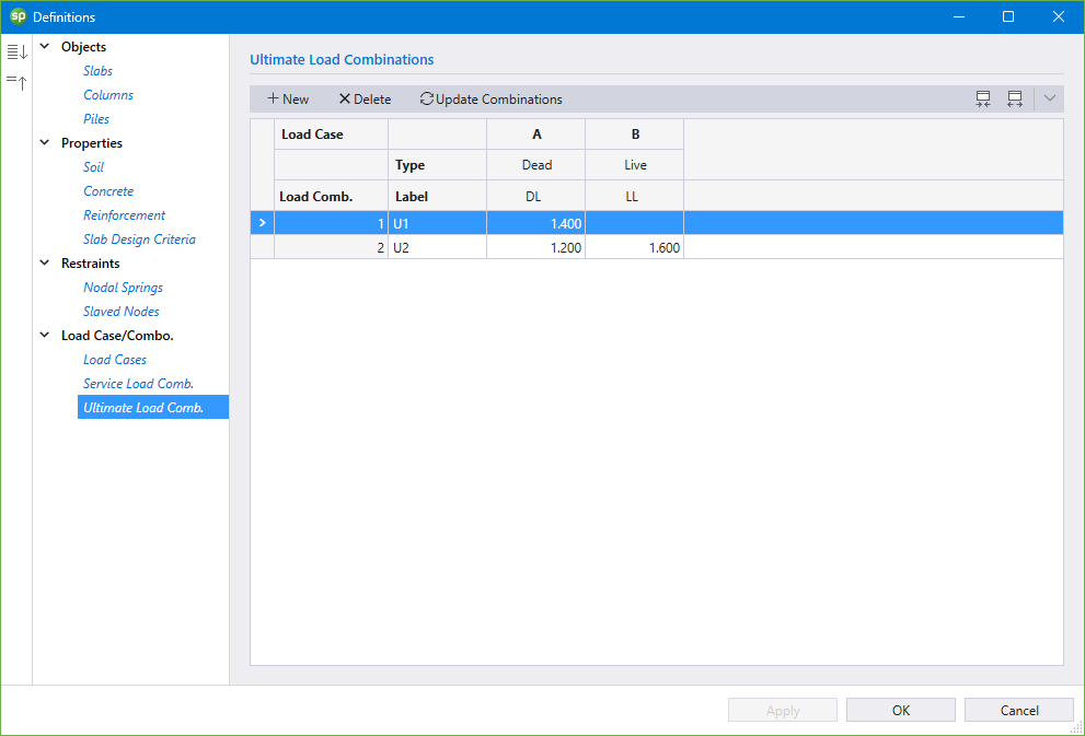
The Ultimate Load Combinations definition consists of the LOAD CASES, LOAD CASE TYPE, LOAD COMBINATION NUMBER, LOAD COMBINATION LABEL, and LOAD FACTORS. Load combinations can also be generated automatically based on the design code in the model.
The Objects that can be created are: Slabs, Columns, and Piles.
You can create Slabs using the Slabs command from the Ribbon.
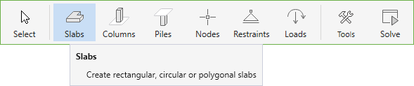
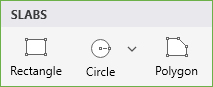
You can draw Rectangular, Circular or Polygonal slabs by using one of the following three tools in the Slabs Left Panel.
If you have already defined a slab type in the DEFINITIONS dialog, select it from the LABEL drop down menu in the Left Panel before you start drawing. You can also simply select the SECTION and PROPERTIES and start drawing, the corresponding definition created will automatically be added to the DEFINITIONS dialog.
To draw a slab shape using the mouse, first select the desired tool.
• Then click on the workspace to begin drawing.
• For circular or rectangular slabs, move your mouse until the desired size is achieved and click again to finish drawing.
• For polygonal slabs keep clicking on the workspace until you create all the desired vertices. You can close a polygon either by clicking the right mouse button or manually clicking on the first vertex point created.
Alternately slab shapes can also be created by using the dynamic input box.
• To display a dynamic input box, press ENTER after you have selected the desired slab tool.
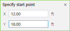
• You will be required to provide the start point (center point for circular slabs).
• Type in the required coordinates and press ENTER.
• Press ENTER once more to display the dynamic input box again. Type in the required quantities i.e. width and height for a rectangular slab or radius for a circular slab and press ENTER to finish drawing.
• For polygonal slabs you will have to keep pressing ENTER to bring out the dynamic input box to provide each vertex. The polygon will be closed once you enter the coordinates of the starting point provided that the shape is geometrically correct.
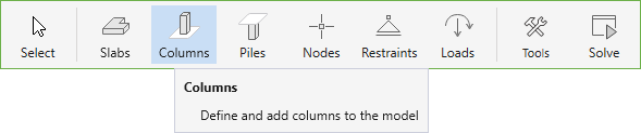
You can create Columns using the Columns command from the Ribbon.
If you have already defined a Column type in the DEFINITIONS dialog, simply select it from the LABEL drop down menu in the Left Panel to assign it to the model. You can also simply select the section type, enter the dimensions and start assigning, the corresponding column definition created will automatically be added to the DEFINITIONS dialog.
To assign a column using the mouse, first decide on the parameters of the column to be assigned. The cursor shape changes to the column selected to be assigned.
• Then click on the workspace to begin assigning.
• You can also marquee select a group of nodes to assign multiple columns at once.
Alternately columns can also be assigned by using the dynamic input box.
• To display a dynamic input box, press ENTER after you have selected the column to be assigned.
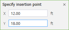
• You will be required to provide the insertion point.
• Type in the required coordinates and press ENTER.
5.2.4.3. Piles
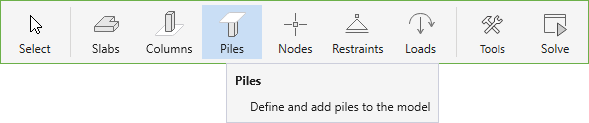
You can create Piles using the Piles command from the Ribbon.
If you have already defined a Pile type in the DEFINITIONS dialog, simply select it from the LABEL drop down menu in the Left Panel to assign it to the model. You can also simply select the section type, enter the dimensions, select the required properties and allowable reactions (if applicable), and start assigning, the corresponding pile definition created will automatically be added to the DEFINITIONS dialog.
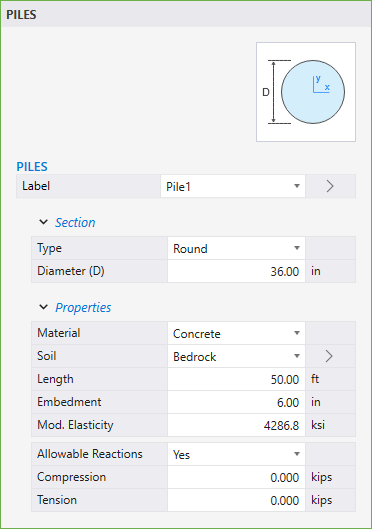
To assign a pile using the mouse, first decide on the parameters of the pile to be assigned. You can also define whether ALLOWABLE REACTIONS are considered for the pile in the Properties section. The cursor shape changes to the pile selected to be assigned.
• Then click on the workspace to begin assigning.
• You can also marquee select a group of nodes to assign multiple piles at once.
Alternately piles can also be assigned by using the dynamic input box.
• To display a dynamic input box, press ENTER after you have selected the pile to be assigned.
• You will be required to provide the insertion point.
• Type in the required coordinates and press ENTER.
You can create Nodes scope using the Nodes command from the Ribbon.
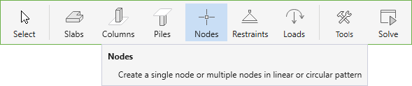
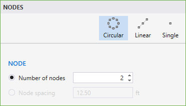
You can draw a Single node, nodes in Linear arrangement or nodes in Circular arrangement by using one of the following three tools in the Nodes Left Panel.
To draw nodes, first select the desired Nodes Tool.
• Select the NUMBER OF NODES or the NODE SPACING option for the Circular and/or Linear tools and enter the desired number of nodes to be created or the spacing at which the nodes are to be distributed.
• Then click on the workspace to begin drawing. If you have selected the Single node tool then the node is created at the point you click.
• Move your mouse until the desired size is achieved and click again to finish drawing.
• You can also marquee select grid intersections to assign multiple nodes at them.
Alternately you can also use dynamic input box.
• To display a dynamic input box, press ENTER after you have selected the node tool and decided on the number or spacing of the nodes to be created.
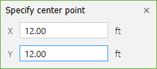
• You will be required to provide the starting point (center point for Circular node distribution).
• Type in the required coordinates and press ENTER.
• If you have selected the Single node tool then the node is created at the point you specify.
• Press ENTER once more to display the dynamic input box again. Type in the required quantities i.e. X and Y coordinates of the end points for linear node distribution or radius for the circular node distribution and press ENTER to finish drawing.
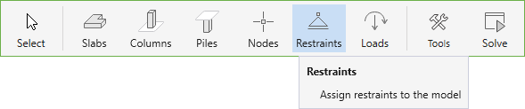
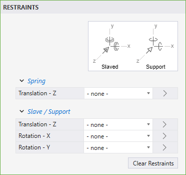
The Restraints that can be assigned are: Nodal Springs, Slaved Nodes, and Supports. You can create Restraints using the Restraints command from the Ribbon.
spMats considers restraints as nodal properties. It is possible to assign more than one kind of restraint to a node at the same time.
• In the SPRING → TRANSLATION - Z and the SLAVE/SUPPORT → TRANSLATION - Z, ROTATION - X and ROTATION - Y boxes, select the required restraint type.
• You can also use the CLEAR RESTRAINTS button to clear any existing restraints and select new ones.
• Next, click on the location you want the restraint to be assigned to.
• You can also marquee select a group of nodes to assign all of them the same restraints.
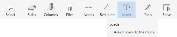
You can create Loads using the Loads command from the Ribbon.
You can assign Point loads or Area loads by using one of the two options that are presented in the Loads Left Panel.

Area loads can only be assigned to Slabs.
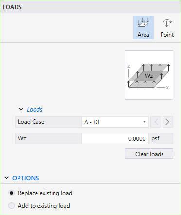
To assign an Area load, make sure that the Area command in the Left Panel is selected. The Left Panel should be displaying various Area Loads options.
• Select the LOAD CASE you want the Area load to belong to. You can always define LOAD CASES in the DEFINITIONS dialog.
• In the Wz box, type in the required load value. Note that the downward forces have negative values.
• From the OPTIONS select if you want to ADD TO EXISTING LOAD on the slab or REPLACE EXISTING LOAD completely.
• Next, click on the slab you want the load to be assigned to.
• You can also marquee select a group of slabs to assign all of them the same area load.
spMats considers Point loads as nodal properties.
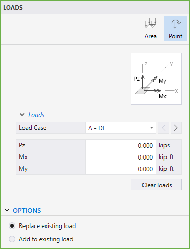
To assign a Point load, make sure that the Point command in the Left Panel is selected. The Left Panel should be displaying various Point Loads options.
• Select the LOAD case you want the Point load to belong to. You can always define LOAD CASES in the DEFINITIONS dialog.
• In the Wz, Mx, and My boxes, type in the required load and moment values. Note that the downward forces have negative values. To determine the direction of the moments Mx and My, use the right-hand rule.
• From the OPTIONS select if you want to ADD TO EXISTING LOAD on the node or REPLACE EXISTING LOAD completely.
• Next, click on the location you want the load to be assigned to.
• You can also marquee select a group of nodes to assign all of them the same point load.
You can open Tools scope using the Tools command from the Ribbon.
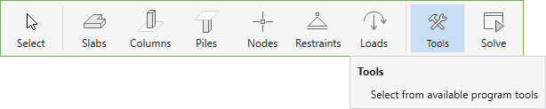
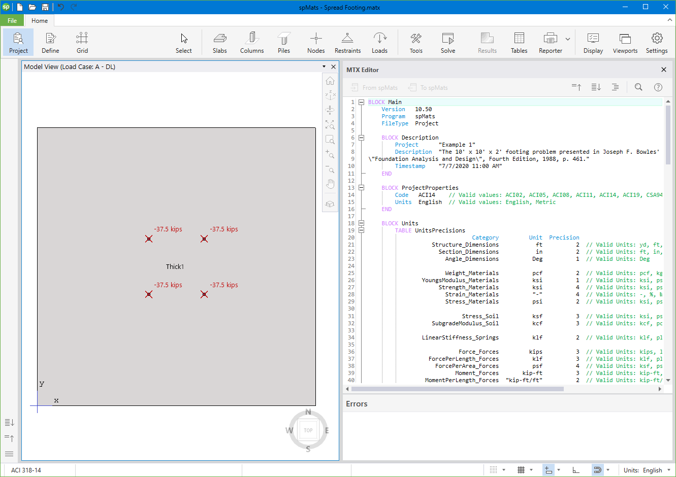
You can open the MTX Editor using the Tools command from the Ribbon.
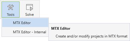
The Main MTX Editor works like a normal text editor. It can be used for opening, editing and saving both project and import/export (exchange) MTX files.
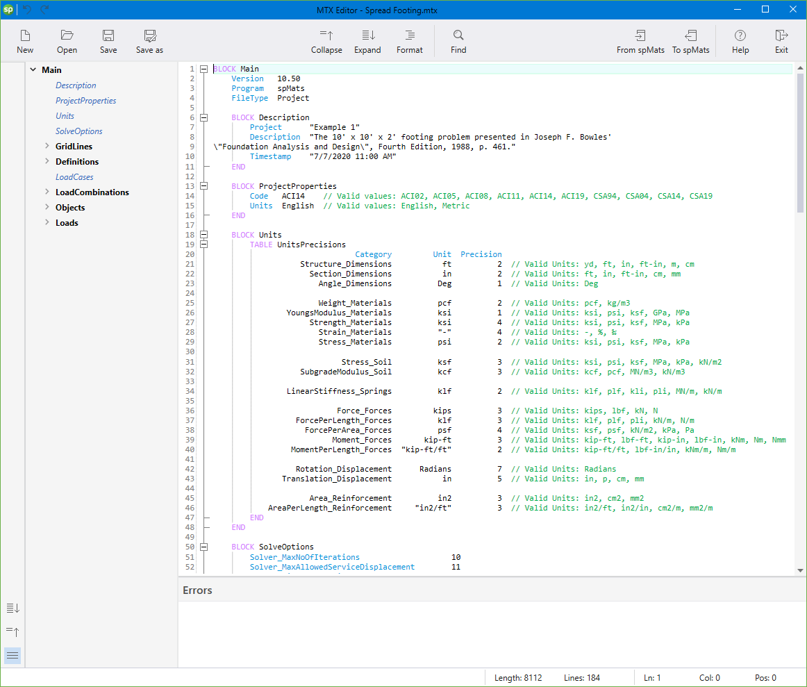
More information about this topic can be found in Section 3.6 and A.3.
You can open the MTX Editor - Internal using the Tools command from the Ribbon.
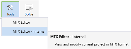
MTX Editor Internal has the exact same interface as the Main MTX Editor. The difference between the two is that while Main MTX Editor can be used to load, edit and save files independent of what is loaded in the GUI, MTX Editor Internal is synced with the spMats project loaded in the main program. It can therefore be easily used to investigate spMats models, compare MTX data with spMats Models and also modify the active spMats models.
More information about this topic can be found in Section 3.6 and A.3.
The model can be edited by using the Left Panel, Left Panel Toolbar or by using right-click at Viewport.
5.2.5.1. Using the Left Panel Objects
The Objects that can be edited are: Slabs, Columns and Piles.
The corresponding Slabs Left Panel provides various tools and options for effectively working with Slabs. You must have the Select command button toggled on to edit the Slabs.
To edit a slab section or properties:
• Click on the slab to select it.
• Then in the Left Panel, simply change the desired parameter.
• If the given set of parameters match the parameters of a pre-defined slab, the new slab will automatically be assigned the existing label.
• If the given set of parameters do not match the parameters of any pre-defined slab, the slab will be assigned a new definition.
The corresponding Columns Left Panel provides various options for effectively working with Columns. You must have the Select command button toggled on to edit Columns.
To edit a single column:
• Click on the column you want to edit to display its properties and position in the Left Panel.
• Change the desired column parameter.
To edit multiple columns at once:
• Use marquee select to select multiple columns at once.
• Notice that if all the selected columns are of the same type, then the section properties are displayed in the left panel and you can change the desired parameter as required.
• If different columns types are selected then only the column label is available to be changed.
The corresponding Piles Left Panel provides various options for effectively working with Piles. You must have the Select command button toggled on to edit Piles.
To edit a single pile:
• Click on the pile you want to edit to display its section, properties, allowable reactions, and position in the Left Panel.
• Change the desired pile parameter.
To edit multiple piles at once:
• Use marquee select to select multiple piles at once.
• Notice that if all the selected piles are of the same type, then the section properties are displayed in the left panel and you can change the desired parameter as required.
• If different piles types are selected then only the pile label is available to be changed.
The corresponding Nodes Left Panel provides various tools and options for effectively working with Nodes. You must have the Select command button toggled on to edit Nodes.
To edit a single node:
• Click on the node you want to edit to display its properties and position in the Left Panel.
• Change the desired node parameter.
To edit multiple nodes at once:
• Use marquee select to select multiple nodes at once.
• Edit the desired nodal properties from the Left Panel.
The corresponding Restraints Left Panel provides various options for effectively working with Restraints.
spMats considers restraints as nodal properties. Therefore, to edit restraints the corresponding nodes have to be selected.
To edit a single restraint:
• Click on the node containing the restraint you want to edit to display its properties and position in the Left Panel.
• Change the desired restraint parameter.
To edit multiple restraints at once:
• Use marquee select to select multiple nodes with desired restraints.
• Change the desired restraint parameter or parameters.
The corresponding Loads Left Panel provides various options for effectively working with Loads.
Editing Area Loads
In spMats Area loads can only be assigned to Slabs. Therefore, to edit Area loads, the corresponding slabs have to be selected.
To edit an area load:
• Click on the slab containing the load you want to edit to display its properties and position in the Left Panel.
• Change the load value as desired.
To edit multiple area loads at once:
• Use marquee select to select multiple slabs with desired loads.
• Change the load value as desired.
Editing Point Loads
spMats considers Point loads as nodal properties. Therefore, to edit Point loads the corresponding nodes have to be selected.
To edit a single point load:
• Click on the node containing the load you want to edit to display its properties and position in the Left Panel.
• Change the desired load parameter.
To edit multiple point loads at once:
• Use marquee select to select multiple nodes with desired loads.
• Change the desired load parameter or parameters.
5.2.5.2. Using the Left Panel Toolbar
You must have the Select command button toggled on in order to use the tools available in the Left Panel Toolbar. You can use the tools in the Left Panel Toolbar to edit various model items.
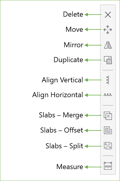
The Delete command is active only when one or more items are selected.
• Select the item or items you want to remove from the model and click Delete to remove.
The Move command is active only when one or more items are selected.
• Select the item or items you want to move and click the Move command.
• Click on the screen to specify the base point from which to start moving. Alternatively, you can also press ENTER and manually enter the coordinates of the base point.
• Drag the selected items to the desired location and click to complete moving. Alternatively, you can also press ENTER and enter the translation vector to move the selected items to their new location.
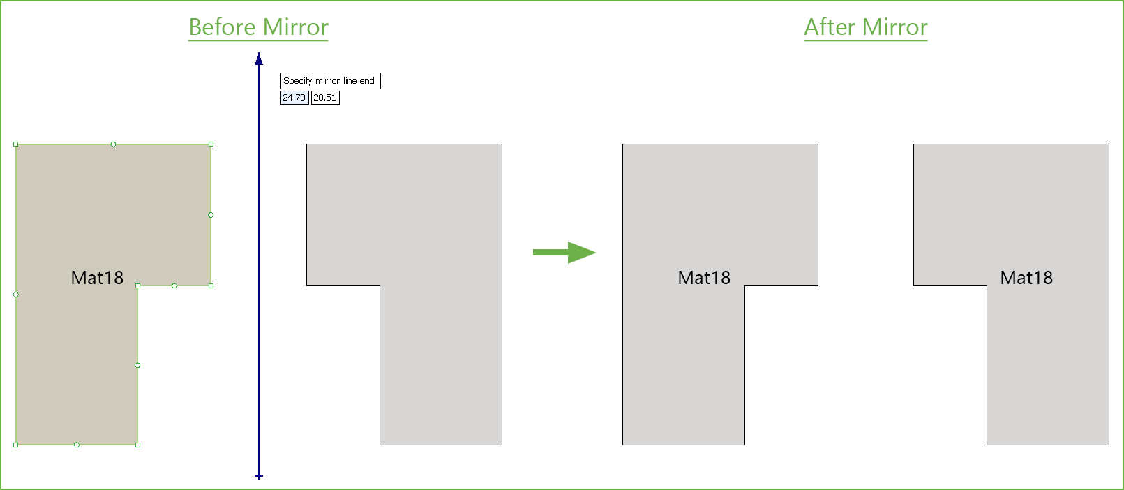
The Mirror command is active only when one or more items are selected.
• Select the item or items you want to mirror and click the Mirror command.
• Click on the screen to specify the start point of the mirror line. Alternatively, you can also press ENTER and manually enter the coordinates of the start of the mirror line.
• Next click on the screen to specify the end point of the mirror line. Alternatively, you can also press ENTER and manually enter the coordinates of the end of the mirror line.
The Duplicate command is active only when one or more items are selected.
• Select the item or items you want to duplicate and click the Duplicate command.
• Click on the screen to specify the base point from which to start the duplicate process. Alternatively, you can also press ENTER and manually enter the coordinates of the base point.
• Drag the duplicated items to the desired location and click to create a new instance. Alternatively, you can also press ENTER and enter the translation vector to move the duplicated instances of items to their new location.
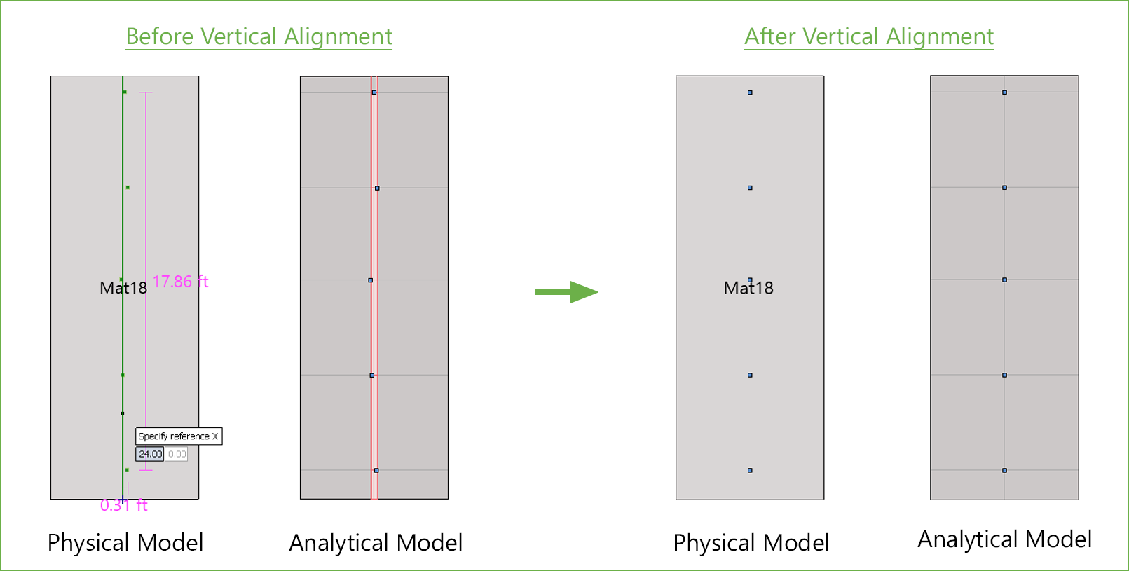
The Align Vertical command is active only when one or more model items are selected. This command is used to eliminate very small difference in location coordinates that could result in unwanted elements with an irregular or high aspect ratio.
• Select the item or items you want to align vertically in a straight line and click the Align Vertical command.
• Click on the screen to specify the reference X point at which to vertically align all the selected items.
• Alternatively, you can also press ENTER and manually enter the coordinate of the X reference point and press ENTER to complete alignment.
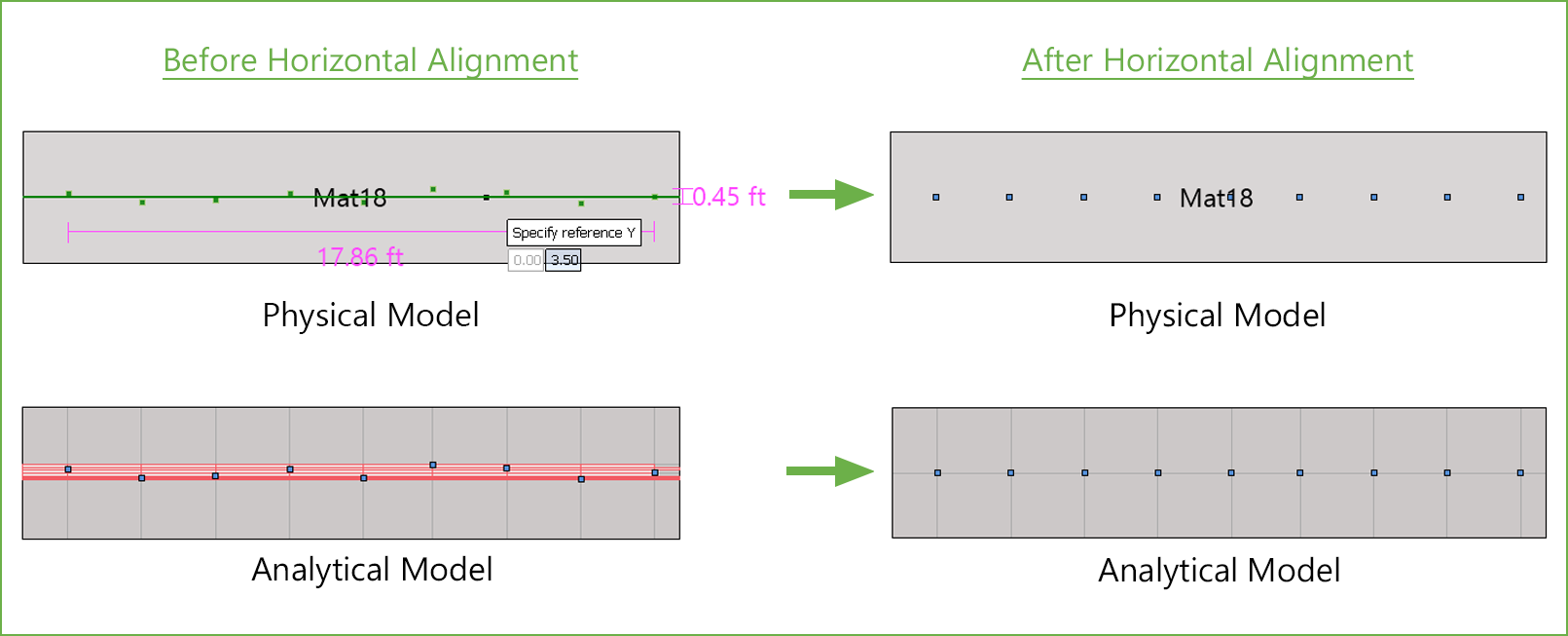
The Align Horizontal command is active only when one or more model items are selected. This command is used to eliminate very small difference in location coordinates that could result in unwanted elements with an irregular or high aspect ratio.
• Select the item or items you want to align horizontally in a straight line and click the Align Horizontal command.
• Click on the screen to specify the reference Y point at which to horizontally align all the selected items.
• Alternatively, you can also press ENTER and manually enter the coordinate of the Y reference point and press ENTER to complete alignment.
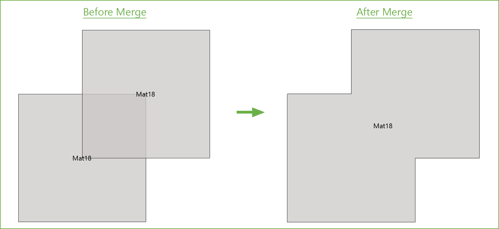
The Slabs – Merge command is active only when more than one slabs are selected.
• Select the slabs that you want to merge and click the Slabs – Merge command.
While merging two or more slabs, the program requires you to select a reference slab, the properties of which will be applied to the final merged slab. These include section type and thickness along with properties like soil, concrete, reinforcement, design parameters, and any area loads applied.
• Click on slab whose properties you want the final merged slab to contain.
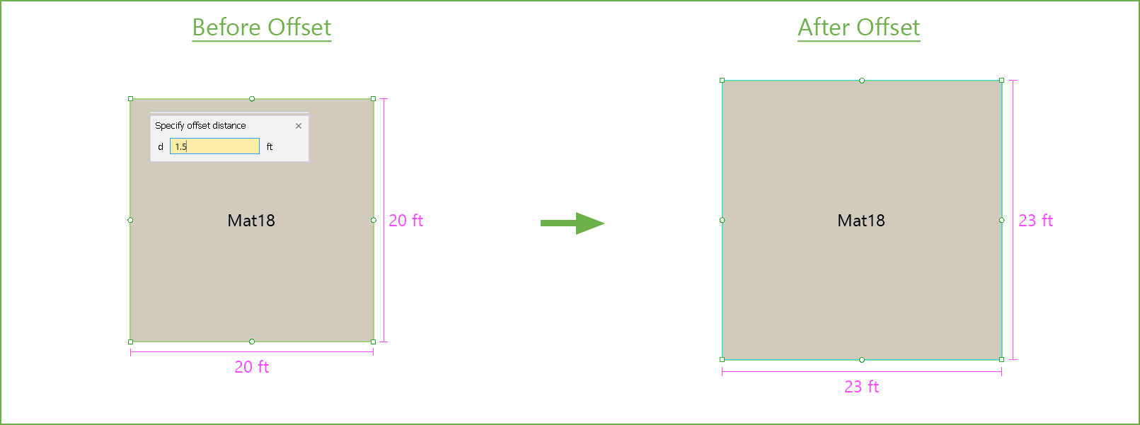
The Slabs – Offset command is active only when one slab is selected. It is used to enlarge or reduce a slab overall size proportionally all around the perimeter to create accommodation for architectural or other features in a slab element.
• Select the slabs that you want to offset and click the Slabs – Offset command.
It is possible to offset the slab inwards or outwards.
• Click the side of the slab you want to offset.
• In the input box that appears, specify the offset distance and press ENTER.
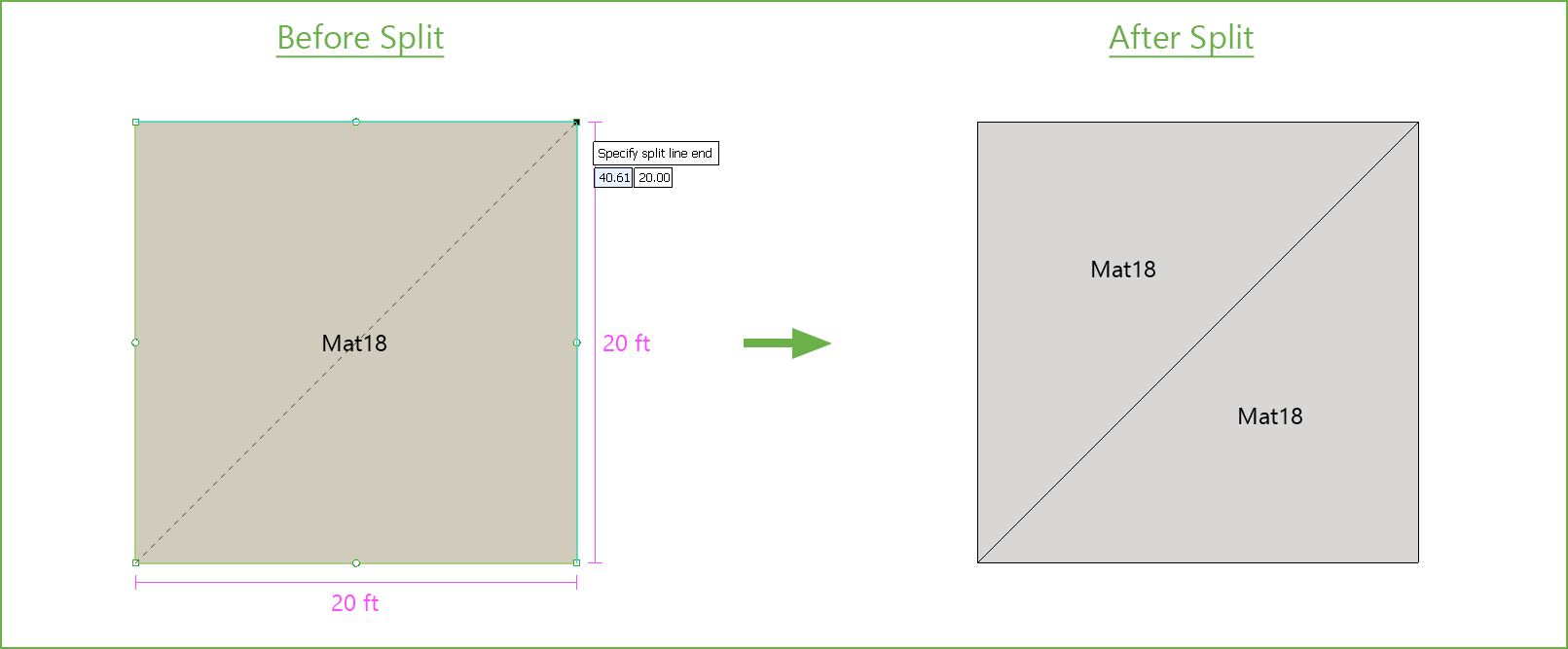
The Slabs - Split command is active only when one or more slabs are selected. Splitting a slab is useful in situations where different load or support options need to be assigned to two separate parts of a slab created previously.
• Select the slabs that you want to split and click the Slabs – Split command.
• Click on the screen to specify the start point of the cutting line.
• Alternatively, you can also press ENTER and manually enter the coordinates of the start of the cutting line.
Note that a slab can be split only if the cutting line starts from outside or one edge of the slab and extends to or beyond the other edge of the slab. Starting a cutting line from any point within a slab will not cut that particular slab.
• Next click on the screen to specify the end point of the cutting line.
• Alternatively, you can also press ENTER and manually enter the coordinates of the end point of the cutting line.
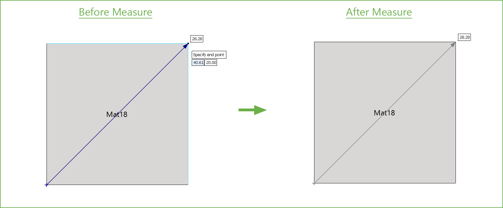
The Measure command is always active and can be used to measure distance between any two points. This command is particularly useful for obtaining the distance between two points along a diagonal.
• Click on the screen to specify the start point. Alternatively, you can also press ENTER and manually enter the coordinates of the start point.
• Click on the screen to specify the end point. Alternatively, you can also press ENTER and manually enter the coordinates of the end point.
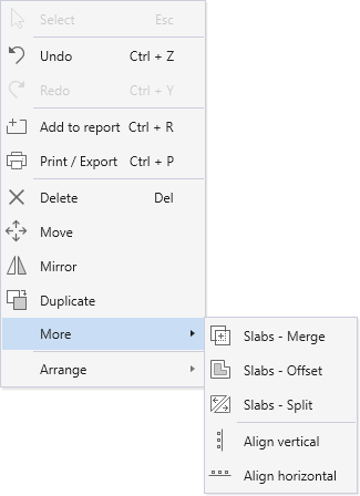
5.2.5.3. Using the Right Click Menu at Viewport
All the tools in the Left Panel Toolbar are also available in the Right Click Menu at Viewport when the Select command button is toggled on.
5.2.5.4. Understanding Slab Layers
While creating models, the need may arise to place one slab on top of another. In this case the properties (including the area load applied on the slab) of the slab on top are considered for solving the model. During modeling, a slab drawn later is always placed above the slab drawn first.
To move a Slab above or below another one:
• Click on the slab to select it.
• Then right click on it to show the Right Click Menu.
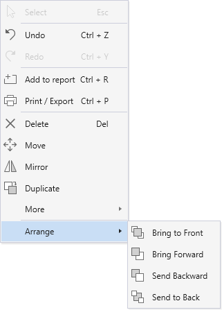
• From the Arrange sub menu, select the desired action.
It should be noted that openings are always on top regardless of the order they are drawn in.
The following figure shows essential Drafting Aids that enhance modeling precision and workflow during the modeling or editing process.
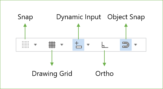
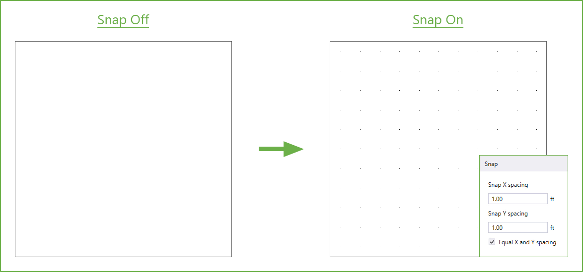
The Snap command enables the cursor to automatically align with a predefined snap points, allowing for precise placement of elements during the modeling or editing process.
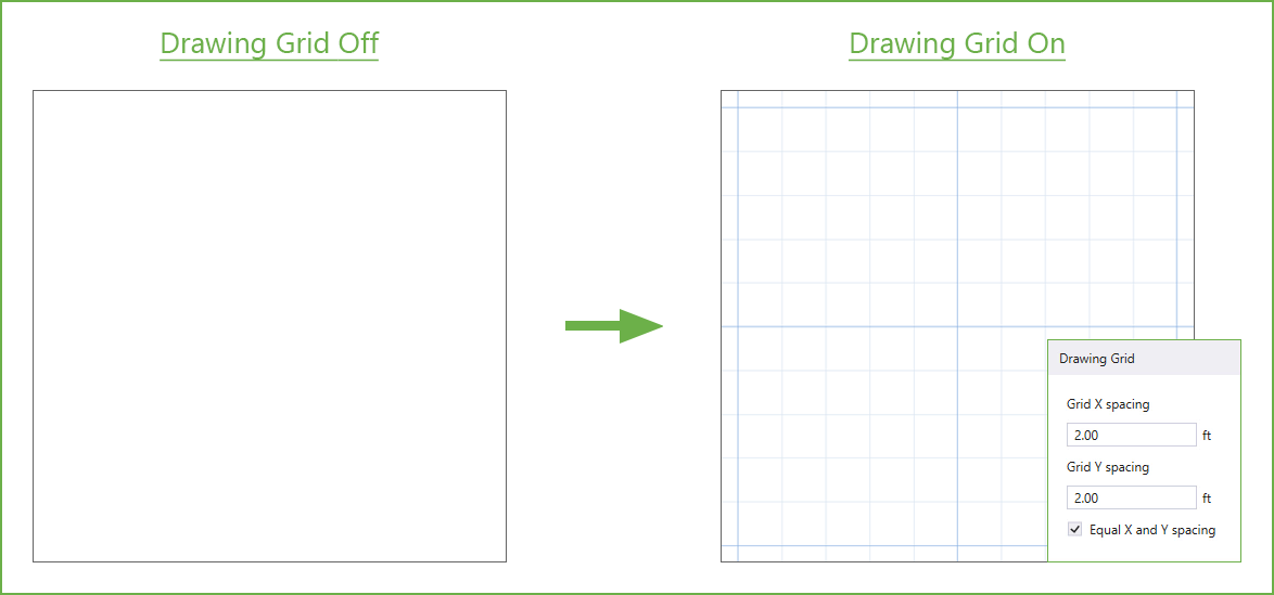
The Drawing Grid command enables the cursor to automatically align with a predefined grids, allowing for precise placement of elements during the modeling or editing process.
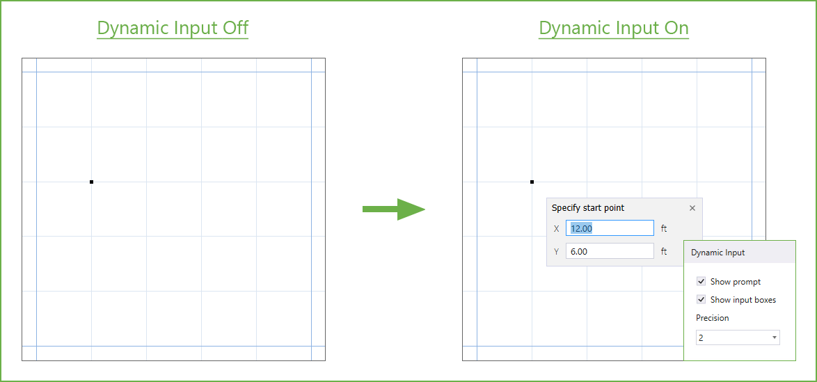
The Dynamic Input command allows to enter coordinates and dimensions directly on-screen near the cursor. This feature can be toggled on or off while creating or editing objects in the viewport.
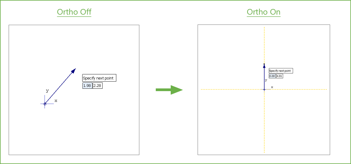
The Ortho command restricts cursor movement to horizontal or vertical directions, when creating or modifying objects.
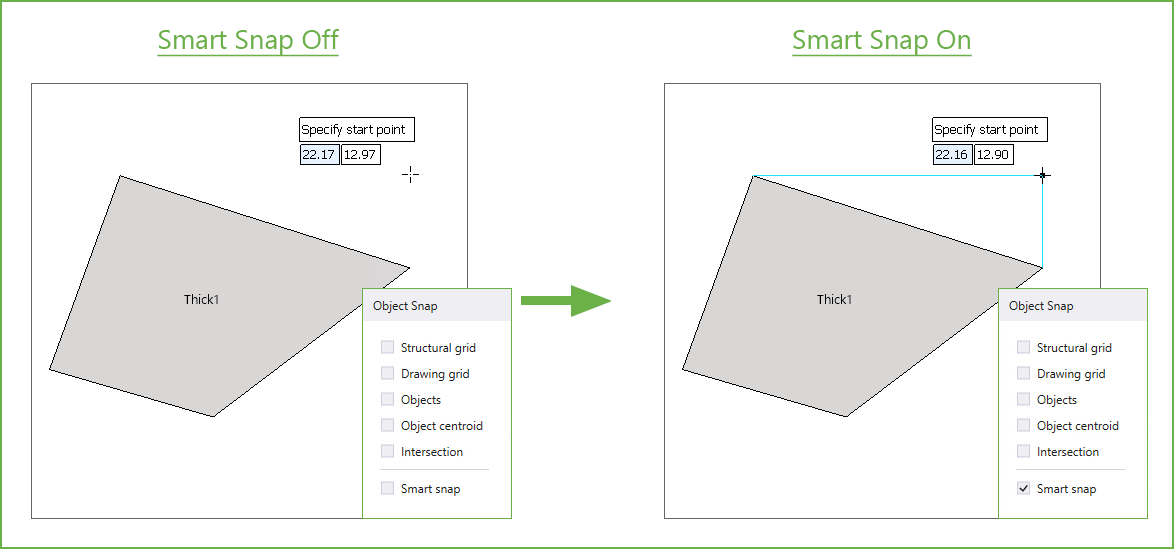
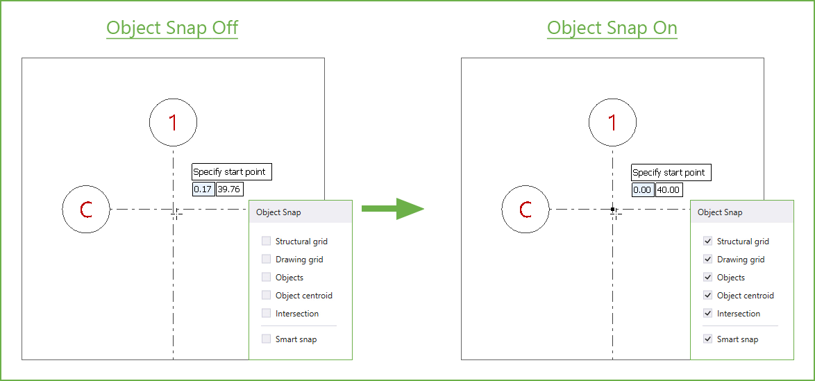
The Object Snap command allows the cursor to automatically detect and lock onto specific reference points such as structural grids, drawing grids, objects, object centroids, and intersections.
Additionally, the Smart Snap command shows Horizontal and Vertical tracking guides to object vertices, midpoints, geometric center and apparent intersections even when the cursor is at a significant distance from the points. The cursor snaps to these guides and any location on the guide can be used as a reference to add to or edit the model.