2.3. Analysis Methods
2.3.1. Overview of Equivalent Frame Method
The equivalent frame method, as described in the code36, is used by spSlab for both analysis and design. The code specifies procedures for the analysis and design of slab systems reinforced for flexure in more than one direction, with or without beams between the supports. A two-way slab37 system, including the slab and its supporting beams, columns, and walls may be designed by either of the following procedures:
• The Direct Design Method
• The Equivalent Frame Method
spSlab uses the Equivalent Frame Method of analysis which is based on extensive analytical and experimental studies conducted at the University of Illinois. Note also that there are no restrictions on the number of slab spans or on dead-to-live load ratios in this method of analysis.
The first step in the frame analysis is to divide the three-dimensional building into a series of two-dimensional frames extending to the full height of the building. Horizontal members for each frame are formed by slab strips as shown in Figure 2.9. For vertical loads, each story (floor and/or roof) may be analyzed separately with the supporting columns being considered fixed at their remote ends (Figure 2.10).
The required reinforcing and resulting deflections for an interior or exterior panel in a floor system shall be combined from the analysis of two equivalent frames in orthogonal directions in order to arrive at the final design.
2.3.1.1. Stiffness Characteristics
The stiffness factors for the horizontal members (the slab beams) and the vertical members (the equivalent columns) are determined using segmental approach.
The moment of inertia of the slab beam elements between the faces of the columns (or column capitals) is based on the uncracked section of the concrete including beams or drop panels. The moment of inertia from the face of the column (or capital) to the centerline of the column (or capital) is considered finite and is dependent on the transverse dimensions of the panel and support. This reduced stiffness (as compared to the infinite stiffness assumed in previous codes) is intended to soften the slab at the joint to account for the flexibility of the slab away from the support. This is consistent with provisions of the code38.
Figure 2.11 shows the changes in stiffness between a slab, and a drop panel, and a column (or capital).
Figure 2.10 - Analytical Model for Vertical Loads for a Typical Story
The computation of the column stiffness is more complicated as it utilizes the concept of an equivalent column. Theoretical slab studies have shown that the positive moment in a slab may increase under pattern loads, even if rigid columns are used, because of the flexibility of the slab away from the column. However, if a two-dimensional frame analysis is applied to a structure with rigid columns, pattern loads will have little effect.
Figure 2.11 - Sections for Calculating Slab-Beam Stiffness, Ksb
To account for this difference in behavior between slab structures and frames, the equivalent column torsional member, as shown in Figure 2.13, runs transverse to the direction in which the moments are being determined. The transverse slab beam can rotate even though the column may be infinitely stiff, thus permitting moment distribution between adjacent panels. It is seen that the stiffness of the equivalent column is affected by both the flexural stiffness of the columns and the torsional stiffness of the slabs or beams framing into the columns. Note that the method of computation of column stiffness is in accordance with the requirements of the code39.
Figure 2.15 shows a schematic representation of the stiffness of typical columns.
Figure 2.12 - Continued
The column stiffness is based on the column height, lc, measured from mid-depth of the slab above, to the mid-depth of the slab below. spSlab calculates the stiffness of the column below the design slab, taking into account the design slab system at its top end. spSlab calculates the stiffness of the column above the design slab taking only the slab depth into account at its bottom end; column capitals, beams, or drops are ignored.
The computation of the torsional stiffness of the member requires several simplifying assumptions. The first step is to assume dimensions of the transverse torsional slab-beam members. Assumptions for dimensions of typical torsional members are shown in Figure 2.14.
The stiffness, Kt, of the torsional member is given by the following expression40:
| Eq. 2-20 |
where: | ||
• Σ | = | denotes summation over left and right side torsional member, |
• Ecs | = | modulus of elasticity for slab concrete, |
• C | = | cross-sectional constant defined in Eq. 2-21, |
• c2 | = | size of rectangular column or capital measured transverse to the direction in which moments are being determined, |
• lt | = | l2L and l2R, lengths of span transverse to l1, measured on each side of the column for ACI 318; for CSA A23.3 value of lt is taken as the smaller of l1a and l2a where l1a is the average l1 and l2a is the average l2 on each side of an interior column. In case of an exterior columns, l1a and l2a are taken respectively as l1 (if the column is exterior with respect to the direction of analysis) and l2 (if column is exterior in the transverse direction) of the adjacent span, i.e. cantilevers, if any, are neglected. |
Figure 2.13 - Equivalent Column
The constant C is evaluated for the cross section by dividing it into separate rectangular parts and by carrying out the following summation41:
| Eq. 2-21 |
where: | ||
• x | = | short overall dimension of the rectangular part of a cross section, |
• y | = | long overall dimension of the rectangular part of a cross section. |
The program divides the section into rectangles in such a way that the value of constant C is maximum (Figure 2.14).
Walls perpendicular to the direction analysis can be modeled as wide columns. If a column/wall runs full length of the total design strip42, the program modifies moment distribution factors to achieve uniform distribution of moments along the column and middle strips. If the width of the wall is less than 75% of the total design strip then no modification of distribution factors is applied. For column/wall widths between 75% and 100% of total strip widths, moment distribution factors are linearly interpolated between regular values and uniformly distributed values.
When beams frame into the column in the direction of analysis, the value of Kt as computed in Eq. 2-20 is multiplied by the ratio of the moment of inertia of the slab with the beam (Isb) to the moment of inertia of the slab without the beam (Is), as shown:
| Eq. 2-21 |

With reference to Figure 2.13, Is is computed from part A (slab without beam), whereas Isb is computed from both parts A and B (slab with beam).
Figure 2.14 - Section of the attached Torsional Members
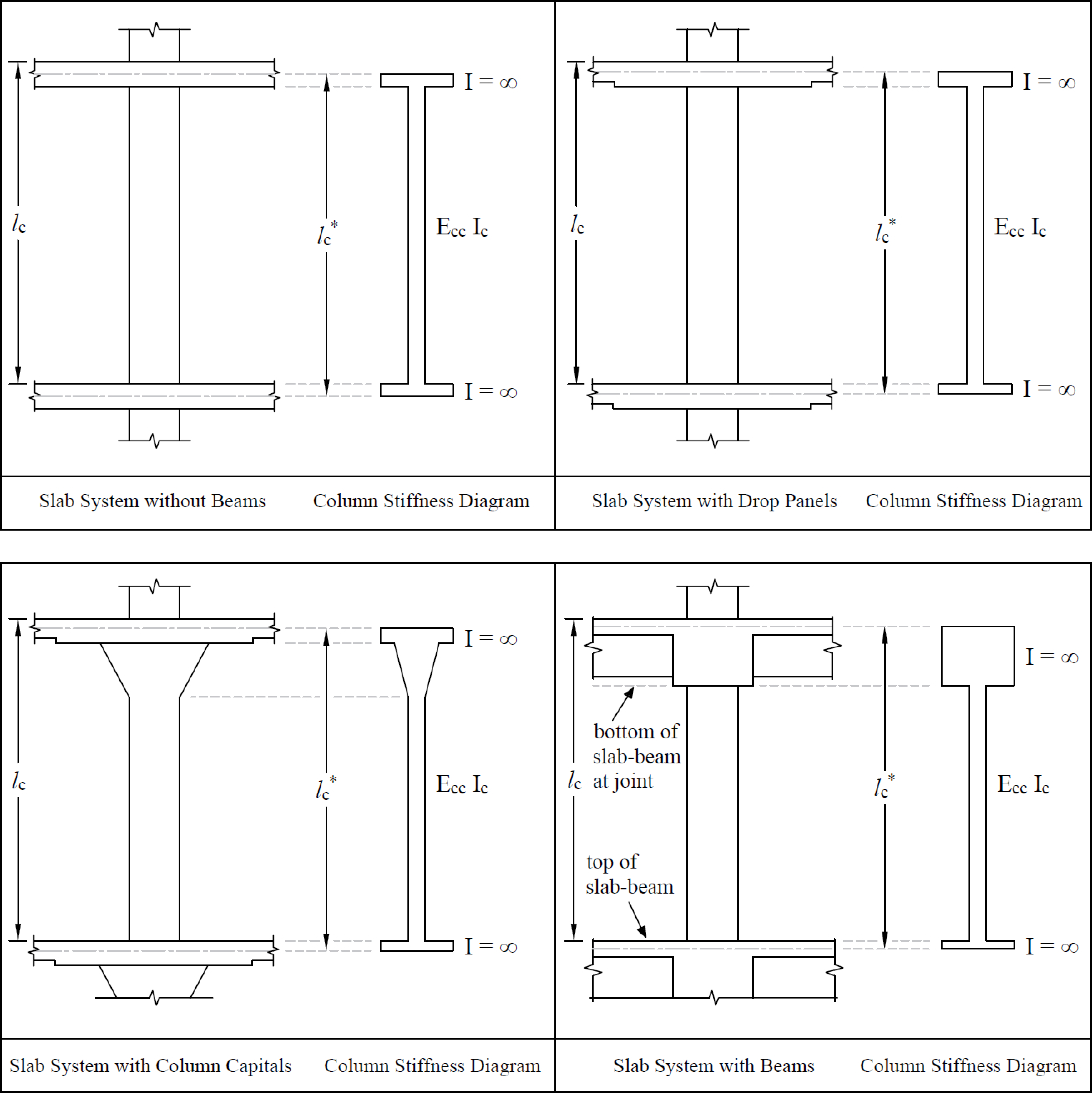
Figure 2.15 - Section for Calculating the Stiffness (Kc) of the Column Below the Design Floor (lc-input, lc*-computed)
Having the column stiffness, Kc, and the stiffness of the attached torsional member, Kt, the stiffness of the equivalent column, Kec, is computed from the equation:
| Eq. 2-23 |
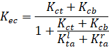
where: | ||
• Kct | = | top column stiffness, |
• Kcb | = | bottom column stiffness, |
• Kta | = | torsional stiffness of the left (Klta) and the right (Krta) member. |
2.3.2. Modeling of Supports
By default spSlab assumes that column-slab/beam joints can only rotate and that they do not undergo any translational displacements. Rotation of a joint is affected by the stiffness of elements it connects i.e. slabs/beams, transverse beams, and columns. Columns are assumed by default to be fixed at their far ends as shown in Figure 2.10. These default assumptions can be altered using the Column and Restraint commands.
By specifying vertical spring support constant with Kz value other than 0, you can allow the joint to displace vertically. This movement is then controlled by the stiffness of the spring Kz in addition to the stiffness of the column below. The column above is assumed not to constrain the vertical movement of the joint. Additional rotational spring support can be applied to the joint by specifying the value of Kry. Also, the far end column conditions can be selected as either fixed or pinned as shown in the Figure 2.16. All elements controlling the displacements of a joint are shown in the Figure 2.16. More information about creating support elements in spSlab/spBeam can be found in Section 5.2.4.2.
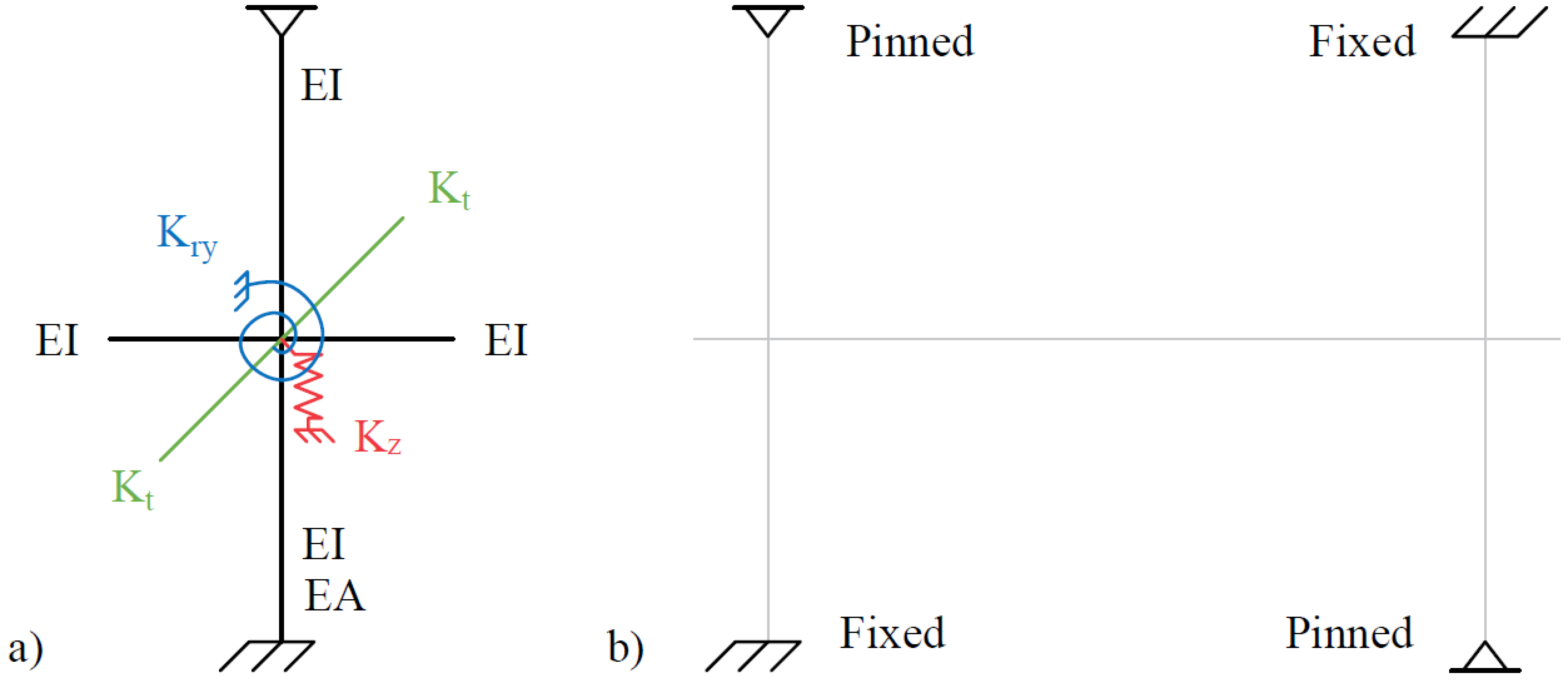
Figure 2.16 - (a) Elements controlling joint displacements (b) Far End Column Boundary Conditions
All applied loads are input as unfactored loads. There are no limitations imposed on the ratio of dead to live loads in the Equivalent Frame Method. Results of gravity load and lateral load analyses may be combined, however, the effects of cracking and reinforcement on stiffness must be accounted for in the lateral load analysis.
The self-weight of the system is automatically calculated and assigned to the reserved load self-weight load case, SELF, which is by default defined in all new data files. The weights of the slabs, drops, and longitudinal and transverse beams are considered in the self-weight computations. Only the concrete weight is considered, the reinforcement weight is ignored. The weight of longitudinal beams is ignored starting at the column centerline, for a length equal to one-half c1, the column dimension in the direction of analysis. This will produce slightly less self-weight than actually present for beams wider than c2, the column’s transverse dimension.
If load case SELF is removed then the program will ignore self-weight in all ultimate load combinations as well as in internally defined service load combination used to calculate displacements.
All superimposed vertical loading is considered to act over the entire transverse width of the slab. For slab systems with beams, loads supported directly by the beam (such as the weight of the beam stem or a wall supported directly by the beams) are also assumed to be distributed over the entire transverse width of the strip. An additional analysis may be required, with the beam section designed to carry these loads in addition to the portion of the slab moments assigned to the beam.
2.3.3.3. Lateral Loading
For lateral loads, each frame should be analyzed as a unit for the entire height of the building (Figure 2.17). Computer programs, such as spFrame, are available for performing such analyses. It should be realized that, for lateral load analysis, slab-beam elements may have a reduced stiffness due to cracking as well as other assumptions made for the effective slab width used for the lateral analysis. The moments obtained from such an analysis may then be input into the equivalent frame model using the program to determine the appropriate design moments under combined vertical and lateral loads.
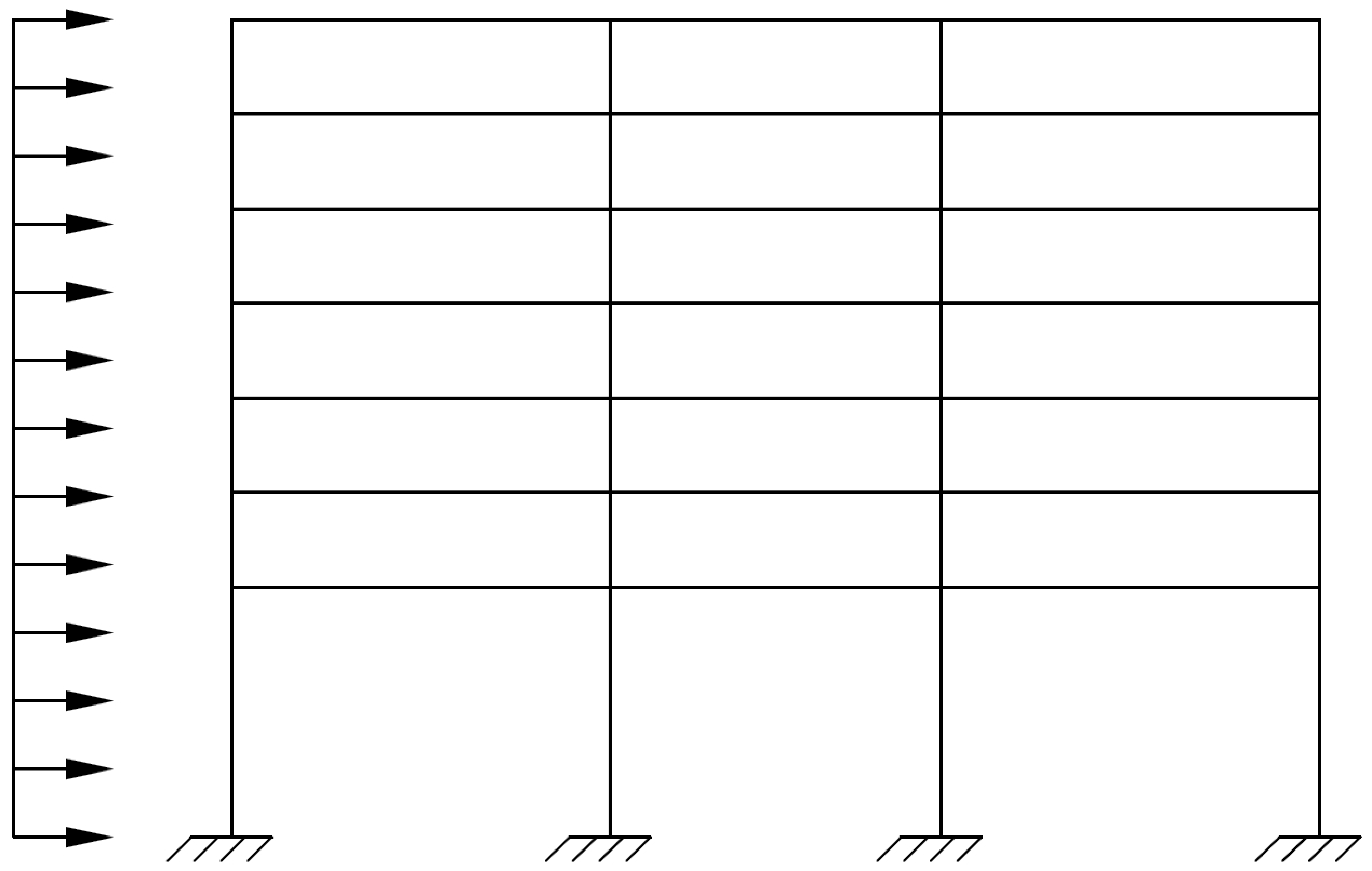
Figure 2.17 - Analytical Model for Lateral Loads
The program distributes the effect of the superimposed lateral load moments to the column strip and middle strip according to the moment distribution factors computed for gravity loads (see Table 2.2 through Table 2.4 later in this chapter).
2.3.3.4. Load Patterns
The analysis of floor systems requires the consideration of several loading configurations. For example, the two adjacent spans loaded may produce the maximum shear stress around a column, while the alternate spans loaded may produce the maximum flexural moments. To cover different loading scenarios the program generates live load case based on the following load patterns (Figure 2.18):
• Pattern No. 1 (All): | All spans loaded with live load, |
• Pattern No. 2 (Odd): | Starting at span 1, alternate spans loaded with live load, |
• Pattern No. 3 (Even): | Starting at span 2, alternate spans loaded with live load, |
• Pattern No. 3+N (SN): | Two spans adjacent to support No. N loaded with live load. |
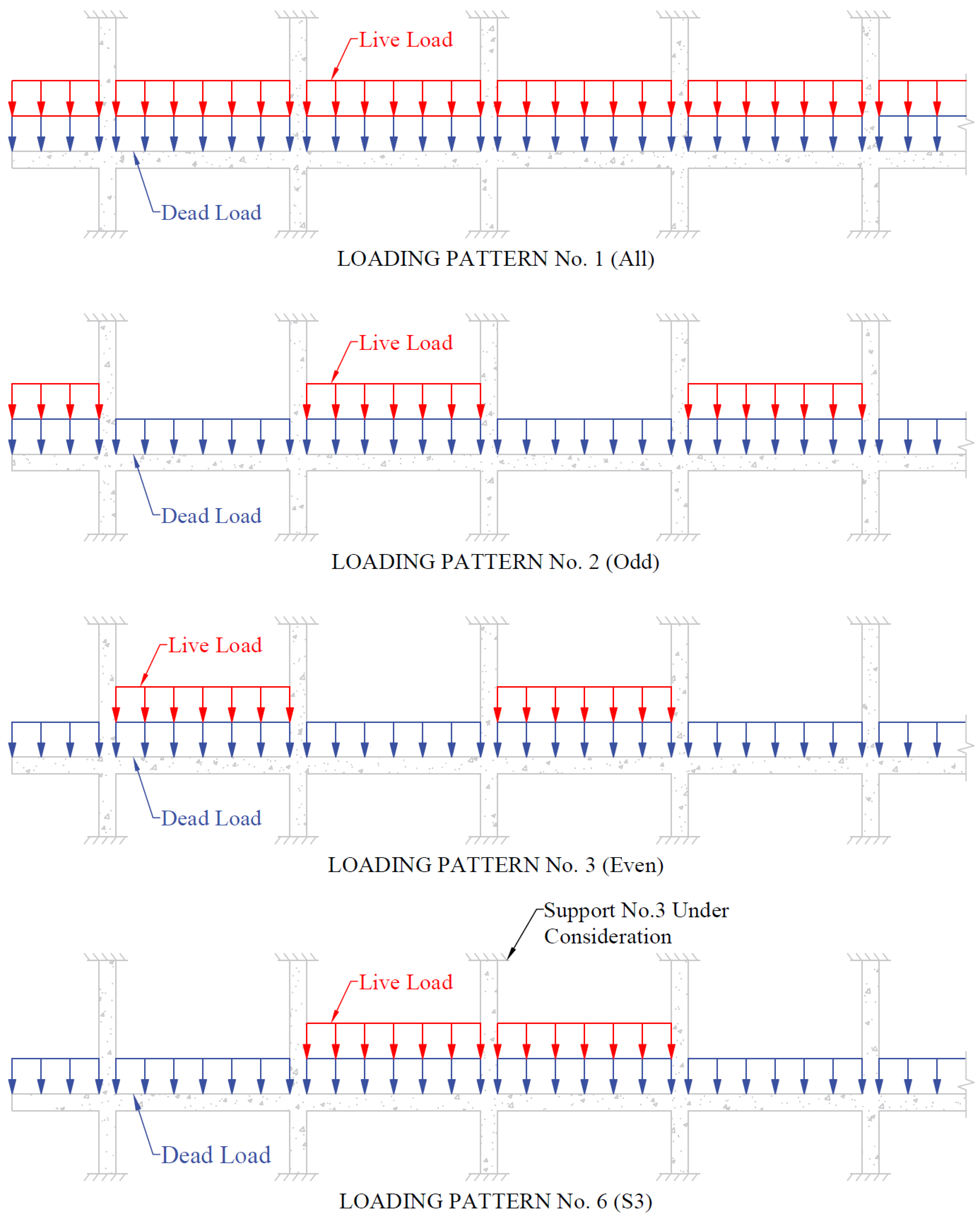
Figure 2.18 - Live Load Patterns
The program reduces the magnitude of live load patterns No. 2 through No. (3+n) by a predefined ratio. For two-way systems, the default live load pattern ratio selected by the program equals 75% as permitted by the code43. The user has the ability to select different value for the pattern ratio within the range 0-100%. If 0% is selected then load patterning effects will be neglected. However, the pattern No. 1 with all spans loaded (as specified by the user) is always considered with full unreduced magnitude.
2.3.4. Column and Middle Strip Widths
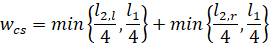
The code44 defines the width of the column strip on each side of the column centerline as being one-fourth of the smaller of either the transverse or the longitudinal span. These widths are printed as part of the design results.
The strip widths at a support are computed by (see Figure 2.19)
• column strip | |
Eq. 2-24 | |
• middle strip | |
| Eq. 2-25 |
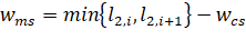
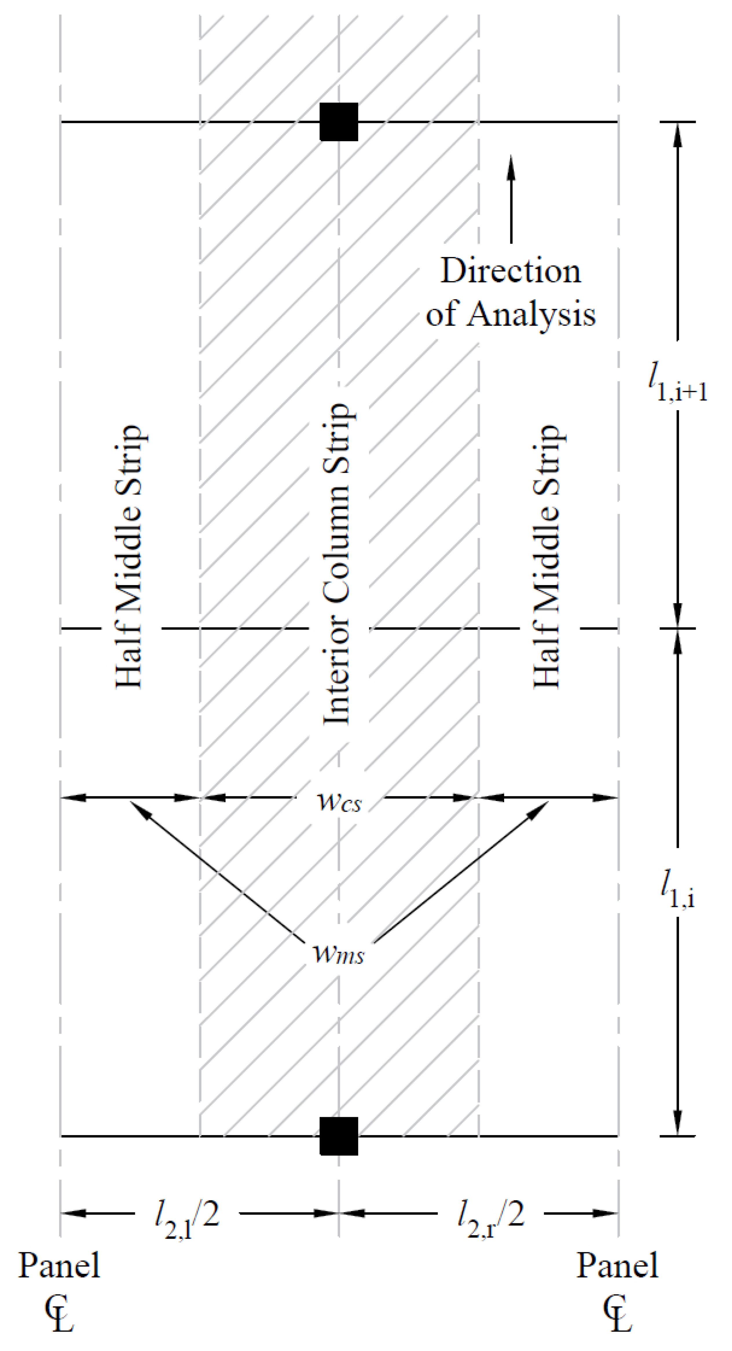
Figure 2.19 - Strip Widths at Support
The strip widths in the span are defined as (see Figure 2.20)
• column strip | |
| Eq. 2-26 |
• middle strip | |
| Eq. 2-27 |
where: | ||
• l1 | = | span length in the direction of analysis, |
• l2,l | = | the input transverse strip widths on the left of column centerline, |
• l2,r | = | the input transverse strip widths on the right of column centerline, |
• l2 | = | l2,l / 2 + l2,r / 2, the total input transverse strip width. |
Figure 2.20 - Strip Widths in Span
If a longitudinal slab band is defined (CSA A23.3-14/04 standard only) then the column strip width is automatically adjusted to be equal to the band width:
wcs = wband | Eq. 2-28 |
If a longitudinal beam exists then the adjusted column strip width, , is calculated by subtracting the beam width, wbeam, from the width of the column strip:
| Eq. 2-29 |
If the user selects the BEAM T-SECTION DESIGN option in Design Options tab under Solve command in the Ribbon, the beam width, wbeam, used by the program will include portion of the slab on each side of the beam equal to projection of the beam below the slab, but not greater than slab thickness45.
Otherwise, only web width is used. If the beam width, wbeam, is greater than the column strip width, wcs, then the adjusted column strip width is set to zero and moment distribution factors are adjusted to apply all column strip moment to the beam. This may occur when modeling a slab band with a wide longitudinal beam for codes other than CSA A23.3-14/04. In case of CSA A23.3-14/04 standard, the dedicated LONGITUDINAL SLAB BAND option in Project Left Panel is available to model slab band systems explicitly.
By selecting USER SLAB STRIP WIDTH and USER STRIP DISTRIBUTION FACTORS options in the Design & Modeling panel under Define command in the Ribbon, the user has the ability to manually override strip widths and moment distribution factors calculated automatically by the program and requires engineering judgment.
Note: For exterior frames, the edge width should be specified to the edge of the slab from the column centerline. Entering edge width greater than l1 / 4 involves engineering judgment regarding two-way behavior of the system and the applicability of the equivalent frame method.
For design purposes46, spSlab considers negative moments as those producing tension at the top of the slab and positive moments as those producing tension at the bottom of the slab.
The negative design moment is taken at the face of the column below the slab, or at the face of the column capital, but in no case is it considered at a location greater than 0.175 of the longitudinal span length, l1, away from the center of the column.47 This imposes a limit on long narrow supports, in order to prevent undue reduction in the design moment. For slab systems with transverse beams, the face of a beam is not considered as the face of support. For end columns with capitals, the negative moments are taken at the midpoint of the capital extension.48 If a positive moment occurs at a support then its value at the face of the column above the slab is considered (or at the support centerline if there is no column above the slab).
spSlab computes the amount of reinforcement for the moments on the left and the right side of the support. The negative design moment is the moment which requires the most area of reinforcement to be resisted. The location, left or right of the support, of the maximum moment may vary when systems differ on each side of the support (for example, a system with beams on one side only).
spSlab automatically calculates the values of strip moment distribution factors for column strips and longitudinal beams (if present). Portion of the total factor moment not assigned to a column strip or a beam is then proportionally assigned to the remaining middle strip.
Note: By checking USER DISTRIBUTION FACTORS option in Design & Modeling panel under Define command in the Ribbon, the user has the ability to manually adjust strip moment distribution factors calculated automatically by the program.
2.3.5.1. ACI 318 and CSA A23.3-9449
The column strips are proportioned to resist the portions in percent of interior negative factored moments according to Table 2.2.50
l2/l1 | 0.5 | 1.0 | 2.0 |
(αf1 l2/l1) = 0 | 75 | 75 | 75 |
(αf1 l2/l1) ≥ 1.0 | 90 | 75 | 45 |
Table 2.2 - Column Strip Percent of Interior Negative Factored Moments at Supports
The column strips are proportioned to resist the portions in percent of exterior negative factored moments according to Table 2.3.51
l2/l1 | 0.5 | 1.0 | 2.0 | |
(αf1 l2/l1) = 0 | βt = 0 | 100 | 100 | 100 |
βt ≥ 2.5 | 75 | 75 | 75 | |
(αf1 l2/l1) ≥ 1.0 | βt = 0 | 100 | 100 | 100 |
βt ≥ 2.5 | 90 | 75 | 45 | |
Table 2.3 - Column Strip Percent of Exterior Negative Factored Moments at Supports
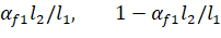
The values αf1 in Table 2.2 and Table 2.3 and βt in Table 2.3 are defined as:
where:
• αf1 = ratio of flexural stiffness of the beam section to flexural stiffness of a width of slab bounded by centerlines of adjacent panels (if any) on each side of the beam in the direction of analysis. For flat plates, flat slabs, and waffle (αf1 l2 / l1) = 0,
• βt = ratio of torsional stiffness of an edge beam section to flexural stiffness of a width of slab equal to the span length of the beam, center-to-center of supports.52 When no transverse beams are present, βt = 0, otherwise
| Eq. 2-30 |

where: | ||
• Ecb | = | modulus of elasticity of beam concrete, |
• Ecs | = | modulus of elasticity of slab concrete, |
• C | = | cross-sectional constant, see Eq. 2-21, |
• Is | = | moment of inertia of the gross section of the slab about its centroidal axis. |
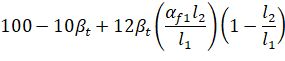
For intermediate values of (l2 / l1), (αf1 l2 / l1) and βt the values in Table 2.2 and Table 2.3 are interpolated using equations Eq. 2-31 and Eq. 2-32.
Percentage of negative factored moment at interior support to be resisted by column strip:
| Eq. 2-31 |
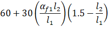
Percentage of negative factored moment at exterior support to be resisted by column strip:
| Eq. 2-32 |
When a column width, c2, is equal to or greater than 75 percent of the tributary strip width l2, the distribution factor for negative column strip moment is linearly interpolated between the factor for regular support, and the factor equal 0.50 (moment uniformly distributed across l2). This extends the requirement of the design code53, by providing continuous linear transition between standard and uniform moment distributions, depending on the relative dimension of the support with respect to strip width. User may override software assumptions by selecting user defined distribution factors.
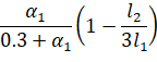
When designing by the CSA A23.3-94 code, a portion of the total positive or interior negative moment equivalent to54:
| Eq. 2-33 |

is resisted by the beam. For exterior supports, the beam is proportioned to resist 100% of the negative moment.
That portion of the moment not resisted by the beam is resisted by the slab. The reinforcement required to resist this moment is distributed evenly across the slab.
For ACI designs the longitudinal beams are proportioned to resist 85 percent of the column strip moments if αf1 l2 / l1 is equal to or greater than 1.0. For values of αf1 l2 / l1 between 0 and 1.0, the beam is designed to resist a proportionate percentage of the column strip moment between 0 and 85.55
The middle strips are proportioned to resist the portion of the total factored moments that is not resisted by the column strips.
The column strips are proportioned to resist the portions in percent of positive factored moments according to Table 2.4.56
l2/l1 | 0.5 | 1.0 | 2.0 |
(αf1 l2/l1) = 0 | 60 | 60 | 60 |
(αf1 l2/l1) ≥ 1.0 | 90 | 75 | 45 |
Table 2.4 - Column Strip Percent of Positive Factored Moments
For intermediate values of (l2 / l1) and (αf1 l2 / l1) the values in Table 2.4 are interpolated using Eq. 2-34 as follows:
| Eq. 2-34 |
Note: For flat plates, flat slabs, and waffle slabs, αf1 l2 / l1 = 0.
For slabs without drop panels (with or without transverse beams) the following moment factors are used57:
• Negative moment at interior column, factor = 0.80
• Negative moment at exterior column, factor = 1.00
• Positive moment at all spans, factor = 0.60
For slabs with drop panels (with or without transverse beams) the following moment factors are used58:
• Negative moment at interior column, factor = 0.825
• Negative moment at exterior column, factor = 1.00
• Positive moment at all spans, factor = 0.60
For slabs with longitudinal slab bands59:
• Negative moment at interior column, factor = 0.90
• Negative moment at exterior column, factor = 1.00
• Positive moment at all spans, factor = 0.90
For slabs with transverse slab bands60:
• Negative moment at interior column in width bb, factor from 0.05 to 0.15 range is selected so that the remaining moment is distributed evenly over the entire frame width (including bb width) and at least one-third of the total factored moment61 is applied to the band width bb.
• Negative moment at exterior column, factor = 1.00
• Positive moment at all spans where (l1 / l2) ≥ 1.0, factor = 0.55
• Positive moment at all spans where (l1 / l2) < 1.0, factor = 0.55 (l1 / l2)
For slabs with beams between all the supports62, the positive and interior negative factored moments are distributed as follows:
| Eq. 2-35 |
Factored negative moments at exterior supports are assigned in 100% proportion to beams.
CSA A23.3-14/04 does not stipulate requirement for distributing moments in slab systems with beams between some (but not all) supports. For estimation of the moment resisted by the beams in this case, the program applies the ACI approach described in the previous section where longitudinal beams are proportioned to resist 85 percent of the column strip moments if αf1 l2 / l1 is equal to or greater than 1.0. For values of αf1 l2 / l1 between 0 and 1.0, the beam is designed to resist a proportionate percentage of the column strip moment between 0 and 85%.
2.3.6. Moment Redistribution
Redistribution of negative moments applies to one-way and beam systems only. It can be engaged using the MOMENT REDISTRIBUTION option in the Design & Modeling panel under Define command in the Ribbon.
The program allows for redistribution of negative moments at supports. Only reduction in negative moments is considered. Increase of negative moments at the support is not taken into account even though it is allowed by the code63. Static equilibrium is maintained meaning that bending moments and shear forces along the span are adjusted in accordance with the reduction of moments applied at the supports. The following procedure is followed to obtain moment redistribution factors at the supports.
From elastic static analysis, the largest moments from all load combinations and load patterns are determined at support faces on both ends of each span except cantilevers. These moments are used to calculate the maximum percentage adjustment of moments, δ, allowed by the codes.
For ACI 318-14, ACI 318-11, ACI 318-08, ACI 318-05, and ACI 318-0264:
| Eq. 2-36 |
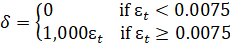
where εt is net tensile strain in extreme tension steel at nominal strength.
For ACI 318-9965:
Eq. 2-37 |
where: | ||
• ρ | = | tension reinforcement ratio, |
• ρ' | = | compression reinforcement ratio, |
• ρb | = | balanced reinforcement ratio. |
For CSA A23.366:
| Eq. 2-38 |
where: | ||
• c | = | distance from extreme compression fiber to neutral axis, |
• d | = | distance from extreme compression fiber to centroid of tension reinforcement. |
In the investigation mode, program uses the area of provided reinforcement to obtain redistribution factors. In the design mode the required reinforcement area is used. Additionally, δ is limited to 20% and not to exceed the maximum values specified by the user. Negative moments at span ends are reduced by the amount of redistribution factors and new moment values are iteratively used to obtain new redistribution factors. This iterative procedure is repeated until the change in distribution factor is negligible (does not exceed 0.01%), but no more than 10 times.
2.3.7. Shear Analysis of Slabs
Shear analysis in spSlab takes into account one way shear and two-way shear. For two-way shear, the program considers contributions of factored shear force67, Vu, and fraction of unbalanced moment transferred by shear,68 γvMunb.
spSlab does not consider torsional stresses in the slab. If in the engineer’s judgment this may control, it must be computed manually.
spSlab checks one-way shear at a critical section located at a distance not less than the effective depth away from the face of the support69. If a concentrated load is applied closer than the effective depth away from the face of the support then critical section is located at the face of the support. Factored shear force at the critical section is obtained from the analysis of the equivalent frame70.
Figure 2.21 - Critical Section for Two-Way Shear
Figure 2.21 shows the general two-way shear area71 used by spSlab. Note that the shaded area represents the general case and is modified for special considerations as explained below.
Beams are considered in the two-way shear as indicated in Figure 2.21 by areas B1, B2, B3, B4, B5, and B6. Ordinarily, transverse beams transfer unbalanced moment to the column through torsion along the beam and not through shear between the slab and column. However, the code leaves the transfer method to the engineer’s judgment concerning the point at which punching shear is no longer applicable and beam shear becomes the dominate element in shear transfer to the column. spSlab makes no such distinction and computes unbalanced moment transfer stress without regard to any beams framing into the column. When a beam is present, the depth of the beam increases the depth of the critical section where it intersects with the beam. The distances from the face of the support to the critical section will also be increased, i.e. effective depth of the beam will be used to calculate the distance instead of effective depth of the slab, if it results in a critical section that is still within the beam. Otherwise, distances to the critical section are not increased.
For circular supports (column or column capital), ACI code and CSA standard differ in their treatment and do not provide clear guidance towards the applicability of an equivalent rectangular section for checking punching shear around circular supports. Therefore, spSlab provides as a default option the calculation of properties of the critical section for punching shear based on circular critical shear perimeter. This option is possible given that both the soffit around the perimeter of circular support and the soffit around the perimeter of circular critical shear perimeter are flat & critical shear perimeter stays circular.
If circular critical shear perimeter is not achievable or possible, then, the program calculates properties of the critical section for punching shear based on an equivalent rectangular support with the same centroid and equal perimeter length72. The equivalent rectangular support is a square with side length equal to π D/4 ≈ 0.785D where D is the diameter of the circular support as shown in Figure 2.22.
Figure 2.22 - Critical Section for Circular Column
While this approach is widely used, it produces an equivalent section but not an equivalent shear perimeter. It is, therefore, left to the end-user discretion to judge the use of the circular shear perimeter as it produces more conservative results compared with the traditional equivalent square option.
The critical section is considered closed if the concrete slab around a column extends to a distance greater than or equal to the specified threshold value. In spSlab, the user may define the distance extended beyond the column face in order to consider the section closed. If the critical section does not meet the distance requirement, it is considered open.
ACI 318-08 code introduced the definition of the shear cap73 which, alternatively to column capital, can be used to increase the critical section around the column. spSlab users can use the capital geometry to model a shear cap and calculate the punching shear through the thickness of the slab itself (shear cap acting as capital). Other failure modes, such as punching within the perimeter of the shear cap, need to be verified by the user manually. The dimensions of the substitute capital have to be selected such that the resulting critical section is equivalent to critical section for a column with a shear cap. ACI code74 requires shear caps to extend beyond the face of the column by at least the distance equal to cap depth, and so depth/extension ratio should not exceed 1.0. For column capitals depth/extension ratio should not be less than 1.0. Therefore to model shear cap acting as capital, the substituted capital should have depth/extension ratio equal to 1.0.
For Interior Supports of Interior Frames
The critical section (Figure 2.23) consists of four vertical surfaces through the slab, located at distances of d/2 beyond the support faces.
The critical section for interior supports of interior frames is always closed. A closed section will have all its faces defined in Figure 2.21 resisting shear as indicated by Eq. 2-39:
| Eq. 2-39 |

If beams frame75 into the column, then the critical section includes the dimensions of the beams (B1 through B6 in Figure 2.21).
Figure 2.23 - Interior Supports of Interior Frames
For Exterior Supports of Interior Frames
The critical section for exterior supports of interior frames (Figure 2.24) will be either closed (full A7 and A6 for the first column or A1 and A2 for the last column in Figure 2.21) or open, depending upon the length of the cantilever in relation to slab thickness. The critical section will be considered closed when the clear cantilever span, lc, is greater than or equal to the distance defined by the user beyond the column face. The default value of the distance is 4h when an ACI code is selected76 and 5d for the CSA standard77.
The user can modify the default value to accommodate scenarios when larger distances are required, e.g. 10h for slabs with openings78.
If beams frame into the column then the critical section includes the contributions from the beam dimensions (B1 through B6 in Figure 2.21).
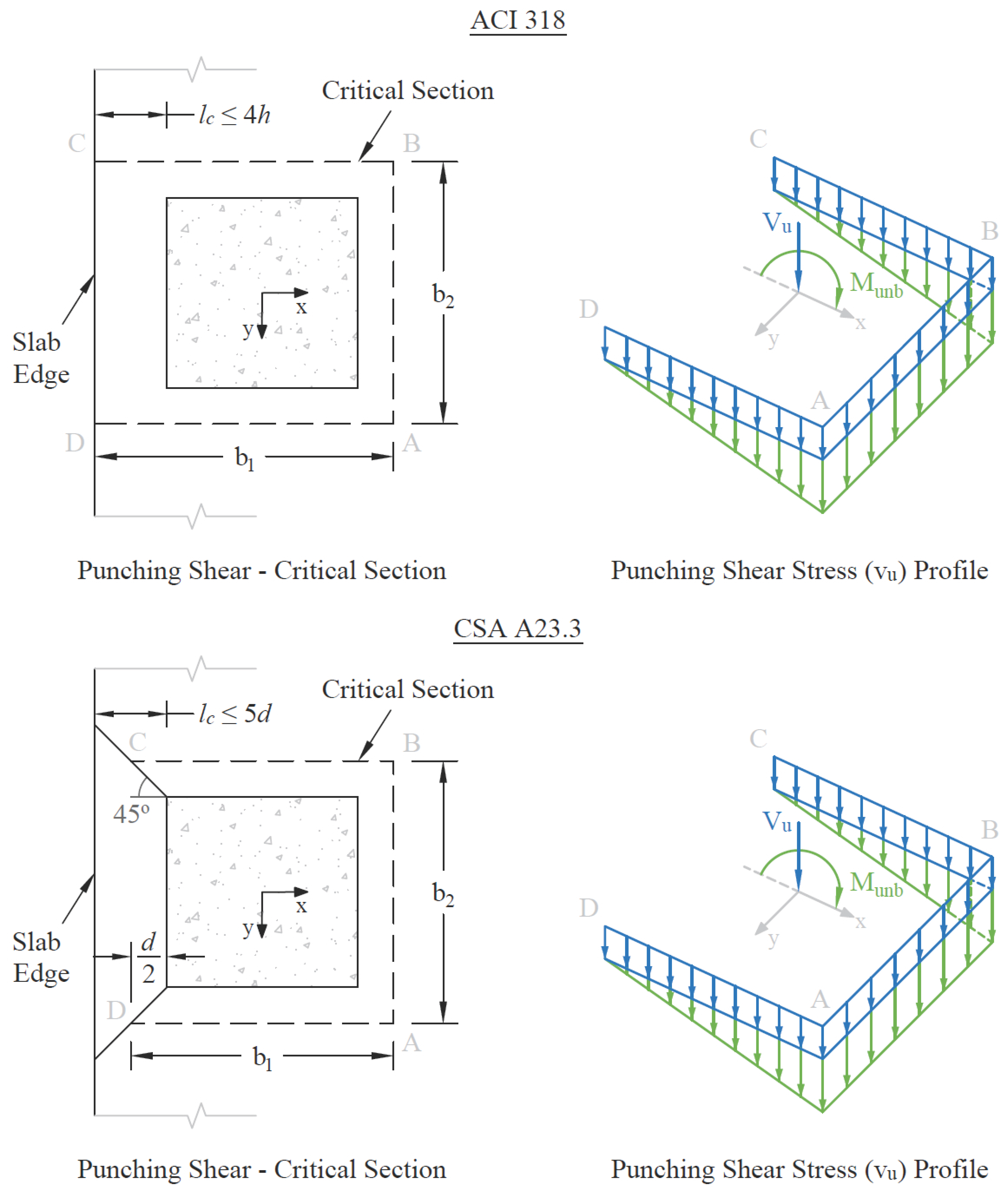
Figure 2.24 - Exterior Supports of Interior Frames
For Interior Supports of Exterior Frames
Figure 2.25 shows the critical section for shear for an interior support of an exterior frame. Note that the section is considered as U-shaped (A5 = 0, A8 = 0, B3 = 0, B4 = 0 in Figure 2.21) and it extends up to the edge of the exterior face of the support. If beams frame into the column, then the critical section includes the contribution from the beam dimensions (B1 through B6 in Figure 2.21). If the exterior cantilever span, lc, is greater than or equal to the distance defined by the user beyond the column face (the default value is 4h when an ACI code is selected81 and 5d for the CSA standard82), the section is treated as closed, that is, the support is treated as an interior support of an interior frame.
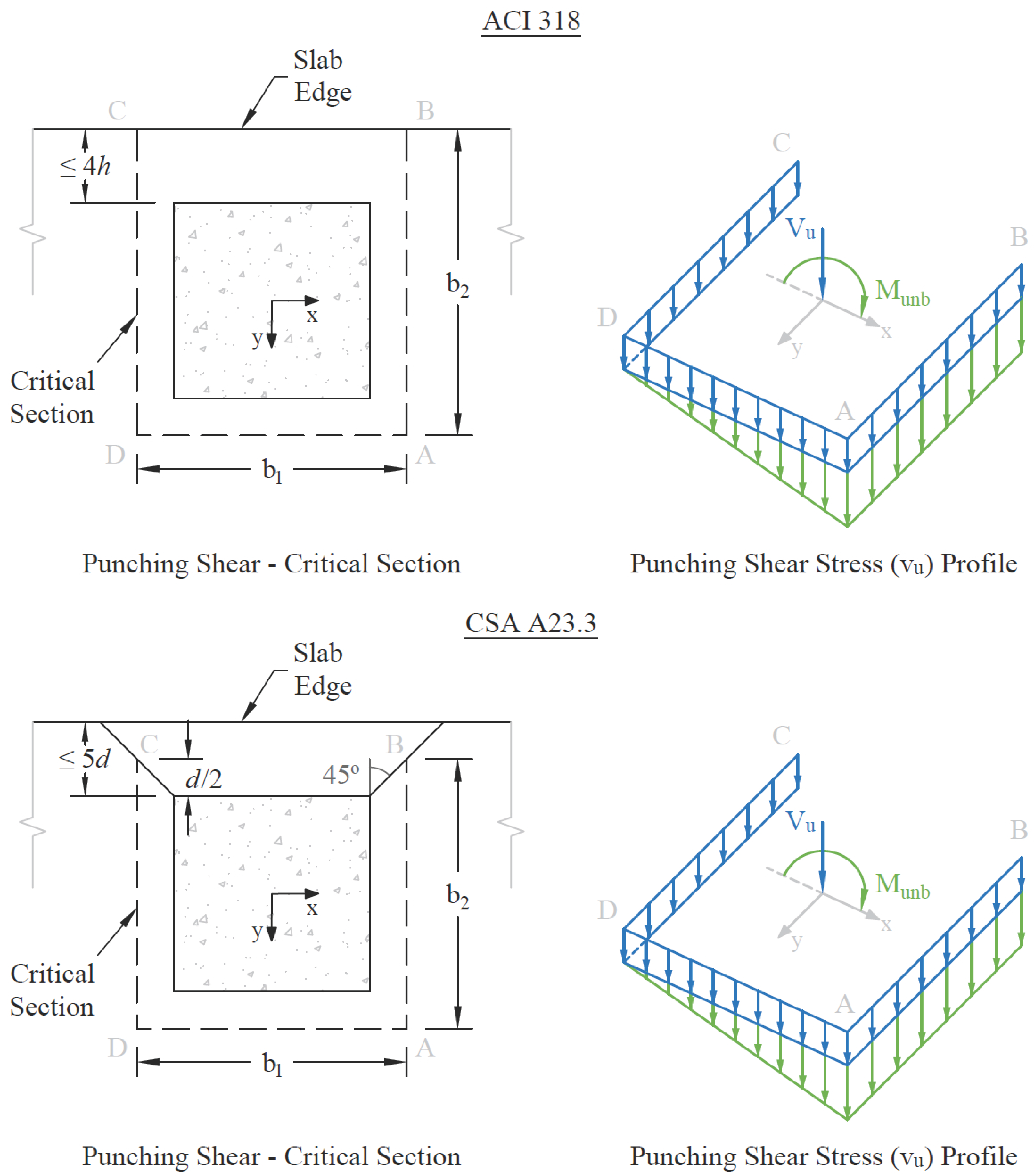
Figure 2.25 - Interior Supports of Exterior Frames
For Exterior Supports of Exterior Frames
The critical section for an exterior support of an exterior frame will typically be L-shaped as shown in the Figure 2.26. If the cantilever span, lc, (in the direction of analysis) is greater than or equal to the distance defined by the user beyond the column face (the default value is 4h when an ACI code is selected81 and 5d for the CSA standard82), then the section is treated as a U-shaped interior support. If, in addition, the cantilever span in transverse direction is greater than or equal to the distance defined by the user beyond the column face, the section is treated as closed. If beams frame into the column, then the critical section includes the contributions from the beam dimensions.
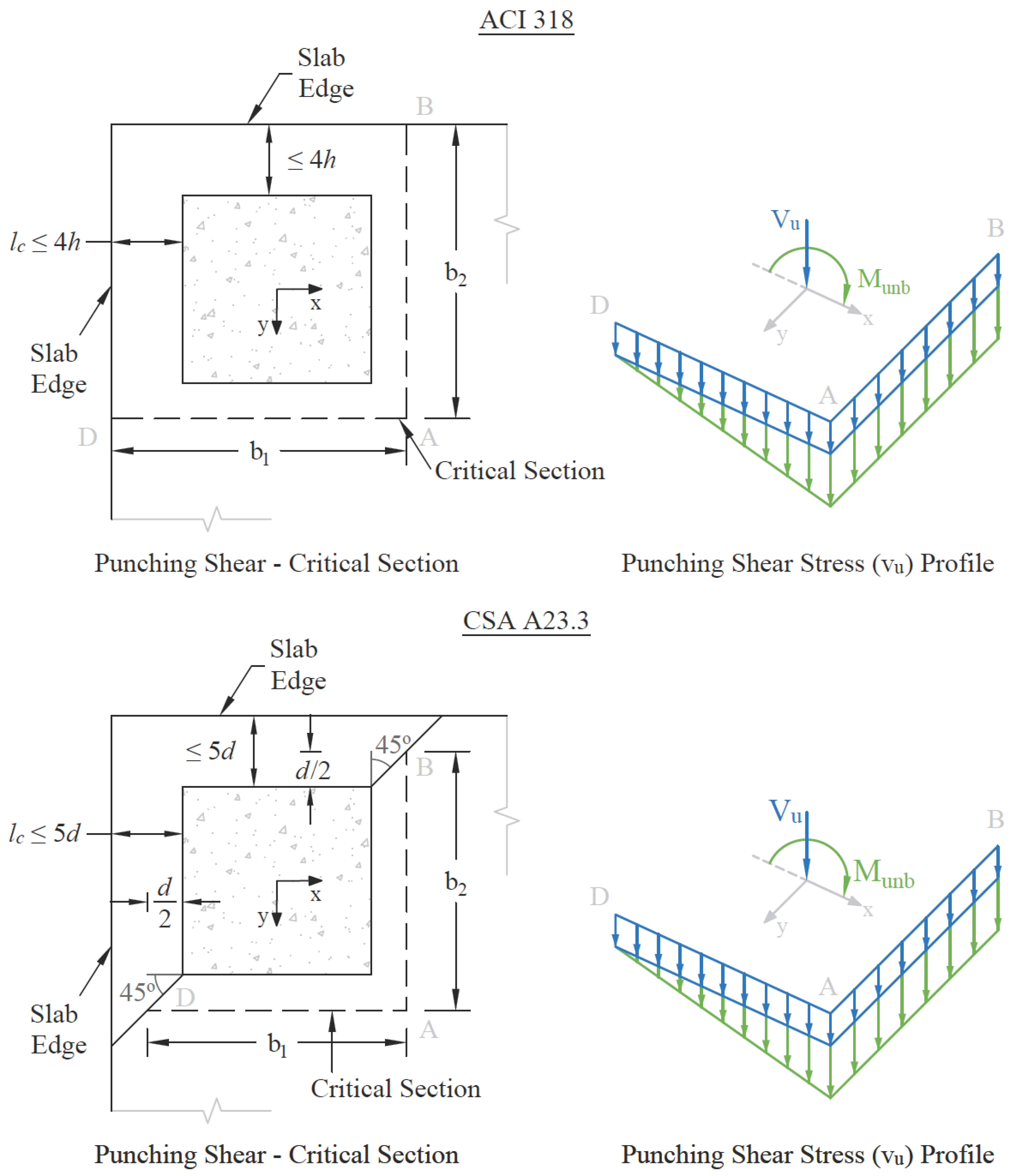
Figure 2.26 - Exterior Supports of Exterior Frames
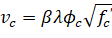
2.3.7.2. Computation of Allowable Shear Stress at Critical Section
One-way shear strength of slabs is limited79 to . Two-way shear strength of slabs is affected by concrete strength, relationship between size of loaded area and slab thickness, loaded area aspect ratio, and shear-to-moment ratio at slab-column connections.
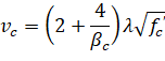
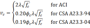
These variables are taken into account in the allowable shear stress, vc, computed at distances of d/2 around the columns and drops (if applicable). For the ACI 318 code, vc is taken as the smallest of the 3 quantities80:
| Eq. 2-40 |
| Eq. 2-41 |
| Eq. 2-42 |
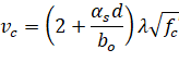

where: | |
• βc = the ratio of the long to the short side of the column, | |
• αs = a constant dependent on the column location, (40 for an interior 4-sided effective critical area, 30 for an exterior 3-sided critical area, 20 for a corner 2-sided effective critical area), | |
• d = distance from the slab bottom to centroid of the slab tension reinforcement at support (average value is used if d changes along critical section perimeter), | |
• bo = the perimeter of the critical section, |
• λ = factor81 reflecting the reduced mechanical properties of light weight concrete equal to 0.75 for all-lightweight concrete, 0.85 for sand-lightweight concrete and 1.0 for normal weight concrete. Refer to Table 2.1 for determination of concrete type.
For the CSA A23.382, the allowable shear stresses are calculated as the minimum of the following metric equations:
| Eq. 2-43 |
| Eq. 2-44 |
| Eq. 2-45 |
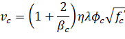
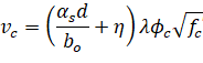
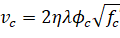
where: | |
• η = 0.19 for CSA A23.3-14/04 and 0.20 for CSA A23.3-94, | |
• αs = a constant dependent on the column location, (4 for an interior 4-sided effective critical area, 3 for an edge column, 2 for a corner column), | |
• d = distance from the slab bottom to centroid of the slab tension reinforcement at support (average value is used if d changes along critical section perimeter), |
• ϕc = resistance factor for concrete83 equal to 0.60 for CSA A23.3-94 and for CSA A23.3-14/04 it is equal to 0.65 for regular and 0.70 for precast concrete,
• λ = factor84 reflecting the reduced mechanical properties of lightweight concrete equal to 0.75 for structural low-density concrete, 0.85 structural semi-low-density concrete and 1.0 for normal density concrete. Refer to Table 2.1 for determination of concrete type,
• 
When the value of d is greater than 300 mm, allowable stress vc obtained from the above three equations shall be multiplied by 1300 / (1000 + d) as required by CSA A23.3-14/04 code85.
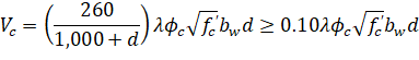
The allowable shear stress around drops when waffle slabs are used is computed as:
| Eq. 2-46 |
For waffle slab systems with valid ribs defined earlier in this chapter, the allowable shear stress is increased by 10% for ACI designs86.
2.3.7.3. Computation of Factored Shear Force at Critical Section
The factored shear force Vu in the critical section, is computed as the reaction at the centroid of the critical section (e.g., column centerline for interior columns) minus the self-weight and any superimposed surface dead and live load acting within the critical section. If the section is considered open, two 45° lines are drawn from the column corners to the nearest slab edge (lines AF and DE in Figure 2.25) and the self-weight and superimposed surface dead and live loads acting on the area ADEF are omitted from Vu.
2.3.7.4. Computation of Unbalanced Moment at Critical Section
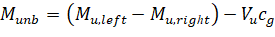
The factored unbalanced moment used for shear transfer, Munb, is computed as the sum of the joint moments to the left and right. Moment of the vertical reaction with respect to the centroid of the critical section is also taken into account by:
| Eq. 2-47 |
where: | ||
• Mu,left | = | factored bending moment at the joint on the left hand side of the joint, |
• Mu,right | = | factored bending moment at the joint on the right hand side of the joint, |
• Vu | = | factored shear force in the critical section described above, |
• cg | = | location of the centroid of the critical section with respect to the column centerline (positive if the centroid is to the right in longitudinal direction with respect to the column centerline). |
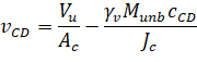
2.3.7.5. Computation of Shear Stresses at Critical Section
The punching shear stress computed by the program is based on the following87:
| Eq. 2-48 |

where: | ||
• Vu | = | factored shear force in the critical section described above, |
• Ac | = | area of concrete, including beam if any, resisting shear transfer. |
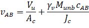
Under conditions of combined shear, Vu, and unbalanced moment, Munb, γvMunb is assumed to be transferred by eccentricity of shear about the centroidal axis of the critical section. The shear stresses computed by the program for this condition correspond to88:
| Eq. 2-49 |
| Eq. 2-50 |
where:
• Munb = factor unbalanced moment transferred directly from slab to column, as described above,
• γv = (1 – γf),
Eq. 2-51
• γv = is a fraction of unbalanced moment considered transferred by the eccentricity of shear about the centroid of the assumed critical section89,
• c = distance from centroid of critical section to the face of section where stress is being computed,
• Jc = property of the assumed critical section analogous to polar moment of inertia.
Factor γf in Eq. 2-51 is calculated as90:
| Eq. 2-47 |
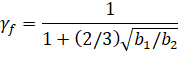
where: | ||
• b1 | = | width of critical section in the direction of analysis, |
• b2 | = | width of the critical section in the transverse direction. |
If an ACI 318 standard is selected then the program provides an option to use an increased value91 of γf. For edge and corner columns with unbalanced moment about an axis parallel to the edge, the value can be increased to 1.0 if the factored shear force at the support doesn’t exceed 0.75ϕVc for edge columns and 0.5ϕVc for corner columns. For ACI 318-99, ACI 318-02, and ACI 318-05, condition that reinforcement ratio in the effective slab width doesn’t exceed 0.375ρb must also be satisfied to apply the increase. For interior columns and for edge columns with unbalanced moment perpendicular to the edge, γf can be increased 25% but the final value of γf cannot exceed 1.0. The increase can be applied if the shear doesn’t exceed 0.4ϕVc. Also, the net tensile strain in the effective slab has to exceed 0.010 for the ACI 318-08, ACI 318-11, and ACI 318-14. For earlier ACI 318 editions, the condition that reinforcement ratio does not exceed 0.375ρb applies.
spSlab calculates vu as the absolute maximum of vAB and vCD. Local effects of concentrated loads are not computed by spSlab and must be calculated manually.
2.3.7.6. Shear Resistance at Corner Columns
For the CSA A23.3 code in design mode, the program performs one-way shear resistance check in the vicinity of corner columns. A corner column is determined in spSlab as the exterior support along an exterior left or exterior right equivalent frame. For slabs with edge beams or drop panels a supplementary check including the contribution of these components should be performed manually.
For the CSA A23.3-94 edition, a critical shear section is located d/2 from the column corner. The minimum length section is selected using an optimization algorithm which analyzes sections at different angles. The extension to the cantilevered portion is considered by a length not to exceed effective slab thickness d.
For the CSA A23.3-14/04 edition, a critical shear section is located not further than d/2 from the edge of the column or column capital. The extension to the cantilevered portion is considered by a length not to exceed effective slab thickness d. The factored shear resistance is calculated as follows92:
| Eq. 2-53 |
where:
• β = factor accounting for shear resistance of cracked concrete93.
2.3.7.7. Shear Resistance in Slab Bands
When performing two-way shear analysis for models with non-continuous longitudinal slab bands a non-standard partial drop panel is anticipated to close the slab band and the calculations are performed as follows. Punching shear around the column is checked using effective depth of the slab band on one side of the column and the depth of the extension drop panel on the other side of the column. On each four sides of the column the critical section is located ½ of the respective depth from the face of the column. Punching shear calculation around the drop panel/slab band assumes that the plane of critical section, which cuts perpendicularly through slab band, is located ½ d of the slab band from the face of column. For three remaining column faces critical section is located ½ d of the slab measured from the respective edges of drop panel or slab band.
2.3.8. One-Way Shear Analysis of Longitudinal Beams and Slabs
When longitudinal beams are present in a span, the program computes the shear reinforcement requirements for the beams. Beam Transverse Reinforcement Capacity dialog box in the program output provides values of Vu, Vc, and Av/s for selected segment locations of each span. Segment lengths are chosen not to exceed the beam section depth. The beginning of first segment and the end of last segment correspond to the locations of critical sections on the left and right support respectively. The critical sections are located at a distance d, the effective beam depth, away from the column face at both the left and the right ends of the beam. However, if concentrated loads are present within distance d from the column face, critical section is selected at the column face.
Vu is computed from the load acting over the entire width of the design strip. The program makes no distinction between shallow beams (αf1 l2 / l1 < 1) and deeper beams (αf1 l2 / l1 > 1).
2.3.8.1. Shear Calculations for ACI 318 and CSA A23.3-94
Shear strength provided by concrete, Vc, is computed by94:
| Eq. 2-54 |
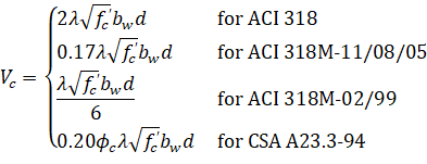
where:
• ϕc = resistance factor for concrete95 equal to 0.60.
In CSA A23.3-94 design, for beams without minimum stirrup reinforcement and greater than 300 mm deep, Vc is calculated from the following equation96:
| Eq. 2-55 |
When Vu > ϕVc /2, the beam must be provided with at least a minimum shear reinforcement of97:
| Eq. 2-56 |
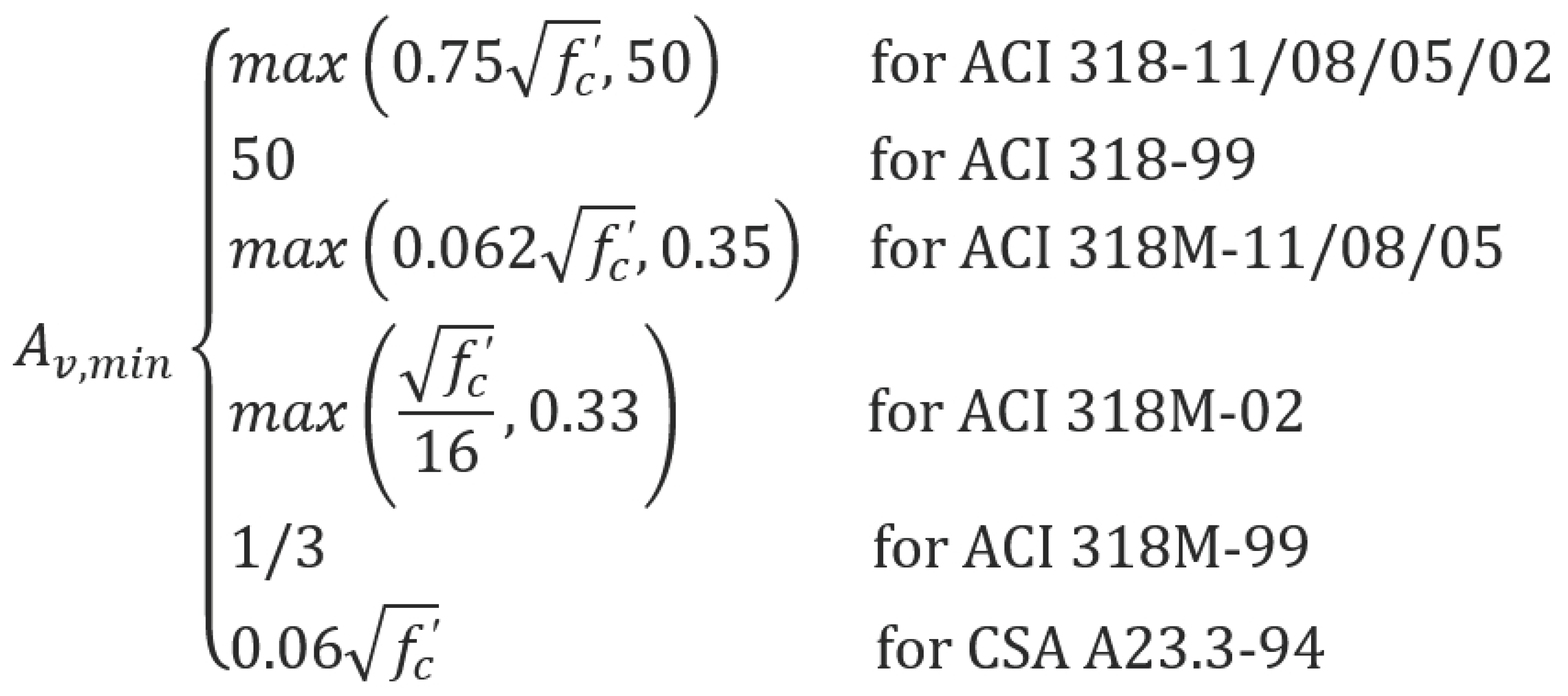
where: | ||
• Av | = | area of all stirrup legs, |
• s | = | stirrups spacing, |
• bw | = | longitudinal beam width, |
• fyt | = | yield strength of the shear reinforcement. |
In the investigation mode, if the ACI-318 spacing requirement for shear reinforcement98 or minimum shear reinforcement requirement are not met, the shear strength of the section is taken as one-half of the shear strength provided by concrete.
When Vu > ϕVc, shear reinforcement must be provided so that:
| Eq. 2-57 |
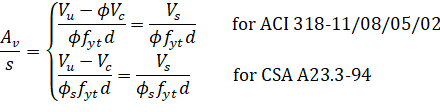
where: | ||
• Vu | = | factored shear force at the section being considered, |
• Vs | = | shear strength provided by shear reinforcement, |
• d | = | effective depth of the beam at the same location, |
• ϕ = strength reduction factor for shear calculations99 equal to 0.85 for ACI 318-99 and equal to 0.75 for ACI 318-14, ACI 318-11, ACI 318-08, ACI 318-05, and ACI 318-02,
• ϕs = resistance factor for reinforcement100 equal to 0.85.
The capacity of shear reinforcement Vs is limited to ( for CSA A23.3-94). When Vu exceeds ϕVc + ϕVs,max (Vc + Vs,max for CSA A23.3-94), the beam section dimensions must be increased or a higher concrete strength must be provided101.
When , the spacing is computed as:
| Eq. 2-58 |
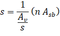
where: | ||
• Asb | = | stirrup bar area (one leg), |
• n | = | number of stirrup legs. |
The maximum stirrup spacing for ACI codes102 must not exceed d/2 or 24 in when . When , the maximum stirrup spacing must be reduced by half, to d/4 or 12 in.
For the CSA A23.3-94 standard103, maximum spacing must not exceed the smaller of 0.7d and 600 mm when or the smaller of 0.35d and 300 mm when .
When for ACI codes and 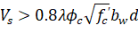 for CSA A23.3-94 code, the beam section dimensions must be increased or a higher concrete strength must be provided104.
The minimum shear reinforcement requirement is waived 105 for joist construction and for beams satisfying the following criteria:
For ACI 318-14, ACI 318-11 and ACI 318-08:
• Beams with depth not exceeding 10 in. [250 mm].
• Beams integral with slabs (assumed by the program for all beams in two-way systems and beams within one-way slabs with overall width larger than effective beam flange width), with beam depth not exceeding 24 in. [600 mm] and not greater than the larger of 2.5 times flange thickness and 0.5 times web width.
For ACI 318-05/02/99:
• Beams with depth not exceeding the largest of 10 in. [250 mm], 2.5 times flange thickness, and half of web width (rectangular beams are assumed by the program to have flange thickness equal to zero and web width equal to beam width).
For CSA A23.3-94:
• Beams with depth not exceeding 250 mm.
• Beams integral with slabs (assumed by the program for all beams in two-way systems and beams within one-way slabs with overall width larger than effective beam flange width), with beam depth not exceeding the larger of 600 mm and 0.5 times web width.
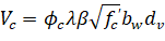
2.3.8.2. Shear Calculation for CSA A23.3-14/04
For CSA A23.3-04 code, the program calculates shear strength Vc provided by concrete from the following equation106:
| Eq. 2-59 |
where: | ||
• ϕc | = | resistance factor for concrete equal to 0.65 for regular and 0.70 for precast concrete, |
• λ | = | factor to account for low-density concrete, |
• bw | = | beam web width, |
• dv | = | effective shear depth equal to greater of 0.9d or 0.72h, |
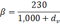
• β | = | factor accounting for shear resistance of cracked concrete, |
• | ||

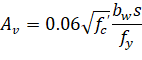
When Vu > Vc, the beam must be provided with at least minimum shear reinforcement107. Additionally minimum shear reinforcement is required for beam sections with overall thickness exceeding 750 mm. Minimum area of shear reinforcement is calculated from the following formula108:
| Eq. 2-60 |
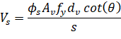
Shear strength provided by shear reinforcement, Vs, is calculated from the following equation109:
| Eq. 2-61 |
where:
• ϕs = resistance factor for reinforcement steel110 equal to 0.85,
• Av = area of shear reinforcement within distance s,
• fy = yield strength of reinforcement,
• dv = effective shear depth equal to greater of 0.9d or 0.72h,
• s = spacing of transverse reinforcement,
• θ = the angle of inclination of diagonal compressive stresses.
Spacing of transverse reinforcement, s, must not exceed the smaller111 of 0.7d and 600 mm when or the smaller112 of 0.35d and 300 mm when .
When 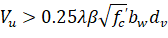 , the beam section dimensions must be increased or a higher concrete strength must be provided113.
The program recognizes special member types and assumes values of β = 0.21 and θ = 42° in the following cases114:
• Slabs (including slab bands for CSA code) having thickness not exceeding 350 mm.
• Beams having thickness not exceeding 250 mm.
• Concrete joist construction.
• Beams cast monolithically with the slab and having the depth below the slab not exceeding one-half of the width or 350 mm.
For other general cases the program utilizes the so called simplified method. The value of θ is assumed as 35°. For sections having or requiring at least minimum transverse reinforcement β = 0.18 is assumed. For sections with no transverse reinforcement the value of β is calculated as follows115:
| Eq. 2-62 |
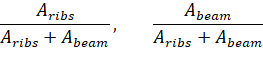
When no ribs are present, one way shear is proportioned to the slab and beam according to the following ratios:
| Eq. 2-63 |
When ribs are present (joist systems), one way shear is proportioned to the slab and beam according to the following ratios of cross-section areas:
| Eq. 2-64 |
Per requirement116 of CSA A23.3-14/04, the program allows distributing one-way shear in the slab between column and middle strips using the distribution factors which are proportional to the factors used for negative moment distribution. The fraction of the shear transferred to the beam remains unchanged irrespective of the use of this feature. This functionality is also provided for other design codes, to be selected at engineer’s discretion.
2.3.8.4. One-Way Shear in Slab Bands (CSA A23.3-14/04)
One-way shear calculations in slab bands are done similar to shear in two-way slabs, except the column strip is substituted by the band strip. Shear forces are distributed between the band and the middle strip proportionally to negative moment distribution factors. Transverse reinforcement is not considered.
When calculating one-way shear capacity for two-way solid and waffle slabs, the contribution of the drop panel cross-section can be optionally selected. For such slabs, the shear capacity is calculated in three regions, with increased Vc values in support (drop panel) locations. In case shear is distributed into column and middle strips, drop panel contribution is divided according to the share of drop panel cross-section area in each strip.
Torsion analysis can be engaged for beam and one-way systems by selecting YES for Consider Torsion run option located in the Project Left Panel under Project command in the Ribbon.
As far as torsional analysis is concerned, it is assumed that columns provide perfectly rigid supports so there is no transfer of torsional moments between spans. Within a span, torsional moments are considered only if a longitudinal beam is present. Torsion can be induced by concentrated and redistributed torsional loads and also, in the case of a beam with unsymmetrical cross sections, by self weight and area loads. A T-section with different flange widths is an example of a cross section which is not symmetrical. It can be obtained if a beam and a slab with different left and right widths are combined in the same span. However, in order for a flange to be considered in the torsional analysis its thickness has to be greater than twice the cover. If a flange is wider than the effective width then only the effective width is taken into account.
The design for torsion is based on a thin-walled tube, space truss analogy. For the Canadian code the simplified method is used. The program allows both equilibrium and compatibility torsion conditions. In the equilibrium mode, which is assumed by default, unreduced total value of the torsional design moment is used in the design. In the compatibility mode117, factored torsional moments that exceed cracking moment Tcr (0.67Tcr for CSA) are reduced to the value of Tcr (0.67Tcr for CSA). However, it is user’s responsibility to determine which mode is appropriate and the program does not perform any redistribution of internal forces if compatibility torsion is selected.
If torsion analysis is engaged then both torsion and shear actions contribute to the amount of required transverse (stirrup) reinforcement. However, additional longitudinal bars distributed along the perimeter of a cross-section are also required to provide torsional capacity.
For torsion design a span is divided into segments in the same way as for shear design. Governing values within a segment are used to design the whole segment. For stirrups, the governing values of torsional moment and shear force (acting simultaneously) will be these that produce the highest intensity of required stirrup area. On the other hand, the required area of longitudinal bars depends only on the torsional moment so the highest absolute value of torsional moment will govern. Since stirrup area depends both on shear and torsion whereas longitudinal bar area depends only on torsion, the governing values for stirrups and longitudinal bars can occur at different locations within a segment and for different load combinations. Governing values along with their location and associated load combination are provided in the design results report.
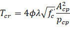
Effect of torsion within a segment will be neglected if the factored torsional moment, Tu, at every segment location is less than one fourth of the torsion cracking moment, Tcr, which equals:
for ACI code118
| Eq. 2-65 |
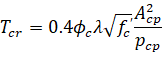
for CSA A23.3-94 code119
| Eq. 2-66 |
for CSA A23.3-14/04 code120
| Eq. 2-67 |
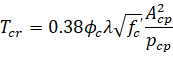
Acp denotes the area enclosed by outside perimeter of concrete section and pcp is equal to the outside perimeter of concrete section.
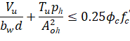
To be adequate for torsion design, a section has to be proportioned in such a way that combined shear stress due to shear and torsion does not exceed the limit value specified by the code. In ACI code this condition reads as121:
| Eq. 2-68 |
The simplified method of CSA A23.3-94 standard defines this relation as122:
| Eq. 2-69 |
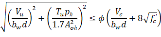
Similar requirement for CSA A23.3-04 reads as follows123:
| Eq. 2-70 |
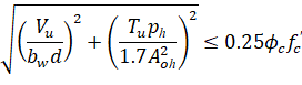
In above relations, Aoh is the area enclosed by centerline of the outermost closed transverse reinforcement and ph is the perimeter of that area. By default, flanges do not contribute to Aoh and ph. For sections with flanges, flanges will only be taken into account for Aoh and ph if the option to include stirrups in flanges is engaged in the torsion design. In the program output, the combined stress (left hand side of the above inequalities) is denoted as vf and the limit value as ϕsvt.
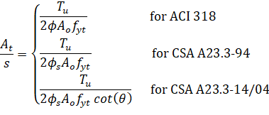
The required intensity of stirrup area to provide required torsional capacity is calculated from the following formula124:
| Eq. 2-71 |
where the gross area enclosed by the shear path125, Ao, is taken as 0.85Aoh × At/s is the quantity per stirrup leg.
Concrete shear and torsion strength reduction factor126, ϕ, for ACI-318 codes is equal to 0.75 for the 99 edition and 0.75 for later editions.
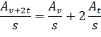
The total requirement for stirrup intensity combining shear and torsion equals127:
| Eq. 2-72 |
This value cannot be taken less than minimum stirrup area required by the codes. The minimum code requirements can be written in the following form128:
Eq. 2-73 |
In addition to stirrup spacing requirement defined for shear, program imposes one more torsion specific requirement for all ACI codes129 which limits the spacing to the smallest of ph/8, and 12 in [300 mm]. Based on the total required stirrup area intensity and spacing requirements, the program attempts to select stirrups taking also into account that if stirrups with more than two legs have to be used then the area of an outer leg must not be less than At.
2.3.9.1. Additional Longitudinal Reinforcement for ACI 318 and CSA A23.3-94
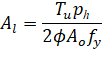
The area of additional longitudinal reinforcement, Al, is calculated from130:
| Eq. 2-74 |
For ACI code it is also checked against the following minimum value131:
| Eq. 2-75 |
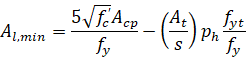
where At / s is calculated from Eq. 2-56 but is not taken less than 25bw / fyt. Longitudinal bars are selected in such a way that their area is not less than Al ≥ Al,min and that number of longitudinal bars in a section is enough to provide a bar in every corner of a stirrup and preserve spacing between bars not higher than 12 in [300 mm]. Also, bar sizes are selected not to have diameter less than No. 3 bar and not less than 1/24 of stirrup spacing for ACI codes132 and 1/16 for CSA standard133:
2.3.9.2. Additional Longitudinal Reinforcement for CSA A23.3-14/04
The additional longitudinal reinforcement, Al, will only be calculated for CSA A23.3-14/04 if COMBINED M-V-T REINF. DESIGN option is unchecked in the Design Options tab under Solve command in the Ribbon. If this option is checked (default setting) then no additional longitudinal reinforcement is calculated because the regular top and bottom reinforcement will automatically be proportioned to resist combined action of flexure, shear and torsion.
Proportioning of longitudinal reinforcement for sections subjected to combined shear and torsion in flexural regions is based on the requirement that the resistance of the longitudinal reinforcement has to be greater or equal to the axial force that can be developed in this reinforcement. In sections with no axial action (Nf = 0 and Vp = 0) that force is equal to134:
• flexural tension side | |
Eq. 2-76 | |
• flexural compression side | |
| Eq. 2-77 |
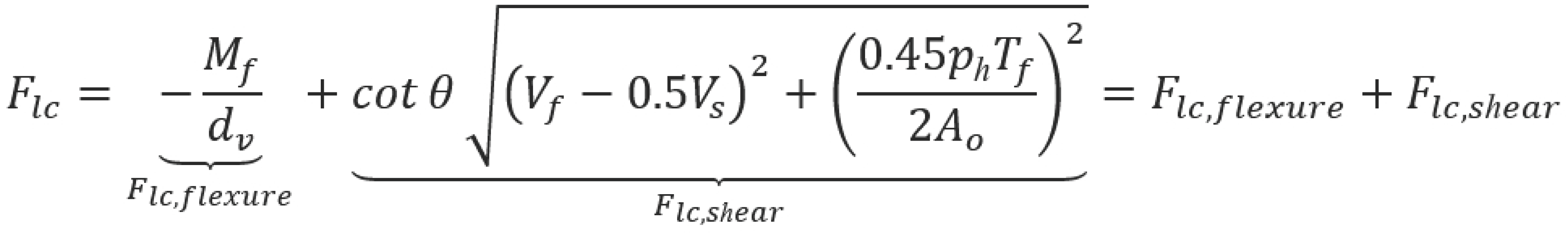
These forces can be decomposed135 into flexure and shear components.
The flexure components, Flt,flexure and Flc,flexure, account for the action of the bending moment, Mf, whereas the shear components, Flt,shear and Flc,shear, account for the action of the shear force, Vf, and the torsional moment, Tf. The amounts of reinforcement needed to resist the flexure components are calculated separately in the flexure and axial design procedure. The total amount of the additional longitudinal reinforcement, Al, needed to resist shear and torsion will be determined as follows:
Eq. 2-78 |
If only torsion is present (Vf = 0 and Vs = 0), then (assuming136 Ɵ = 35º) Al would reduce to
| Eq. 2-78 |
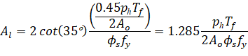
which is comparable (and conservative) to the additional amount of longitudinal reinforcement due to torsion required in accordance with the previous edition of the CSA A23.3 standard.137
In the investigation mode when transverse and longitudinal reinforcement is input by the user, the program checks the combined shear and torsional capacity of the system in terms of required and provided reinforcement area. In other words, the provided area of reinforcement is compared to the area of reinforcement required to resist applied loads. This is a different approach than for flexure and shear actions without coupling where design forces are directly compared to capacity. In the case where torsion and shear stirrup requirements are combined, the approach of comparing total reinforcement area is more convenient since it does not require dividing stirrup area into a part that resists torsion only and a part that resists shear only. For consistency, additional longitudinal reinforcement required for torsion and shear is also checked in terms of provided and required area. Other requirements, e.g. bar or stirrup spacing, number of longitudinal bars, area of stirrup outer leg, and combined stresses in concrete due to shear and torsion are checked also. Exceeded capacity and other conditions are flagged in the Design Results section of the report.
2.3.10. Deflections
2.3.10.1. Instantaneous Deflections
Instantaneous deflections are obtained directly by the program from elastic analysis of the defined system for three load levels. The first corresponds to dead load only, the second corresponds to dead load plus sustained part of live load only, and the third corresponds to dead load plus live load on all spans (total deflection). The deflection occurring when the live load is applied can be computed as the total load deflection (due to the dead and the live load) minus the dead load only deflection138.
Depending on the option selected by the user, the program will calculate flexural stiffness of the members based on either gross moment of inertia or the effective moment of inertia which takes cracking into account.
The program results section provides detailed summary of the frame section properties, frame effective section properties, column and middle strip properties at midspan, and a summary of extreme deflection values for each load level along the span.
When calculating the deflections for effective (cracked) section properties, the frame solution is obtained for three load levels: dead load, dead load plus sustained part of live load, and dead load plus full live load on all spans. Flexural stiffness is assumed corresponding to the load level.
A reduction in the flexural stiffness caused by cracking leads to an increase in deflections. Several methods of deflection analyses taking cracking into account are reviewed in Ref. [22]. The program uses the approach based on the effective moment of inertia as permitted by the code139.
The effective moment of inertia, Ie, developed by Branson (Ref. [17]) and incorporated into the code equals:
| Eq. 2-102 |
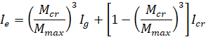
where:
• Ig = moment of inertia of the gross uncracked concrete section,
• Icr = moment of inertia of the cracked transformed concrete section140,
• Mcr = cracking moment,
• Mmax= maximum bending moment at the load level for which the deflection is computed.
To calculate Ie for two-way slabs, the values of all terms for the full width of the equivalent frame are used in Eq. 2-102. This approach averages the effects of cracking in the column and middle strips.
The value of Ie at midspan for a simple span and at support for a cantilever is taken141 to calculate flexural stiffness of a member.
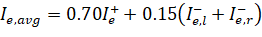
For other conditions, an averaged effective moment of inertia, Ie,avg is used. For spans with both ends continuous, Iframe is given by142.
| Eq. 2-103 |
where: | ||
• Ie+ | = | effective moment of inertia for the positive moment region, |
• Ie,l– | = | effective moment of inertia for the negative moment region at the left support, |
• Ie,r– | = | effective moment of inertia for the negative moment region at the right support. |
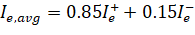
For spans with one end continuous the value of Iframe is given by143:
| Eq. 2-104 |
where: | ||
• Ie+ | = | effective moment of inertia for the positive moment region, |
• Ie– | = | effective moment of inertia for the negative moment region at the continuous end. |
2.3.10.3. Long-Term Deflections
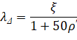
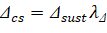
The program estimates additional long-term deflection resulting from creep and shrinkage, Δcs, by multiplying the immediate deflection due to sustained load, Δsust, by the factor, λΔ, equal to144:
| Eq. 2-105 |
where:
• ξ = time dependent factor with the maximum value of 2.0 (the actual value is interpolated from the values and the chart given in the code145 based on the load duration specified by the user in the input),
• ρ' = ratio of compressive reinforcement at midspan for simple and continuous spans and at support for cantilevers.
Deflection due to the sustained load, Δsust, is the deflection induced by the dead load (including self weight), plus sustained portion of the live load.
And long-term deflection resulting from creep and shrinkage equals:
| Eq. 2-106 |
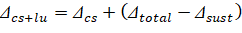
The program calculates incremental deflection which occurs after partitions are installed in two ways. In the first approach, it is assumed that the live load has been applied before installing the partitions and the incremental deflection equals146:
| Eq. 2-107 |
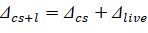
In the second approach, the assumption is that the full live load, including the sustained portion of the live load, has been applied after the partitions are installed which results in the incremental deflection equal to147:
| Eq. 2-108 |
The total long-term deflection (Δtotal)lt is also calculated as148:
| Eq. 2-109 |

2.3.10.4. Deflections of Two-Way Systems
Calculation of deflections of reinforced concrete two-way slabs is complicated by a large number of significant parameters such as: the aspect ratio of the panels, the vertical and torsional deflection of supporting beams, the stiffening effect of drop panels and column capitals, cracking, and the time-dependent nature of the material response. Based on studies (Ref. [20]-[22]), an approximate method consistent with the equivalent frame method was developed (Ref. [23]) to estimate the column and middle strip deflections.
Under vertical loads, Reference 20 indicates that the midspan deflection of an equivalent frame can be considered as the sum of three parts: that of the panel assumed to be fixed at both ends of its span, Δf,ref and those due to the known rotation at the two support lines, Δθ,L and Δθ,r. Calculation of midspan deflection of the column strip or the middle strip under fixed-end conditions is based on M/EI ratio of the strip to that of the full-width panel:
| Eq. 2-110 |
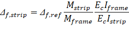
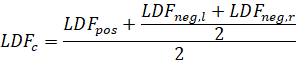
The ratio (Mstrip/Mframe) can be considered as a lateral distribution factor, LDF.
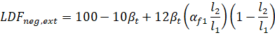
For ACI and CSA A23.3-94 codes the lateral distribution factor, LDF, at an exterior negative moment region is:
| Eq. 2-111 |
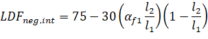
The LDF at an interior negative moment region is
| Eq. 2-112 |
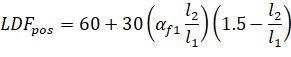
The LDF at a positive moment region is:
| Eq. 2-113 |
where: | ||
• αf1 | = | the ratio of flexure stiffness of a beam section to the flexural stiffness of a width of slab bounded laterally by centerlines of adjacent panels on either side of the beam, |
• βt | = | ratio of torsional stiffness of an edge beam section to the flexural stiffness of a width of slab equal to the span length of the beam, center-to-center of the supports (see Eq. 2-30). |
For CSA A23.3-14/04 code lateral distribution factors are based on tabulated values presented earlier in the chapter.
When αf1 l2 / l1 is greater than 1.0, αf1 l2 / l1 will be set equal to 1.0.
The column and middle strip LDF’s can be computed by.
| Eq. 2-114 |
| Eq. 2-115 |
where: | ||
• LDFneg,l | = | LDF for the negative moment region at the left end of the span, |
• βt | = | LDF for the negative moment region at the right end of the span. |
The total midspan deflection for the column or middle strip is the sum of three parts:
| Eq. 2-116 |
where: | ||
• Δθ,l, Δθ,r | = | midspan deflection due to rotation of left and right supports, respectively. |
The above procedure was implemented starting in v5.00 to follow the reference recommendations exactly and eliminate overestimation of the column strip deflection and underestimation of the middle strip deflection especially for the exterior span.
The deflections should be used in conjunction with the deflections obtained from an analysis in the transverse direction. For square panels (l1 = l2), the mid-panel deflection is obtained from the following equation as shown in Figure 2.27.
| Eq. 2-117 |
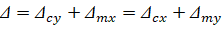
For rectangular panels, (l1 ≠ l2), the mid panel deflection is obtained from:
| Eq. 2-118 |
Figure 2.27 - Deflection Computation for a Square Panel