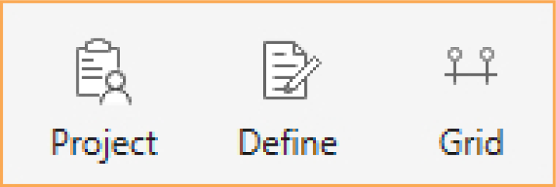
In the Start Screen under Projects, select the New Project option, then select Empty Project option from the New Project dialog box. The model development process may require general input regarding a specific project. Project Information is entered through the Project command button, and Structural Grids are entered through the Grid command button.
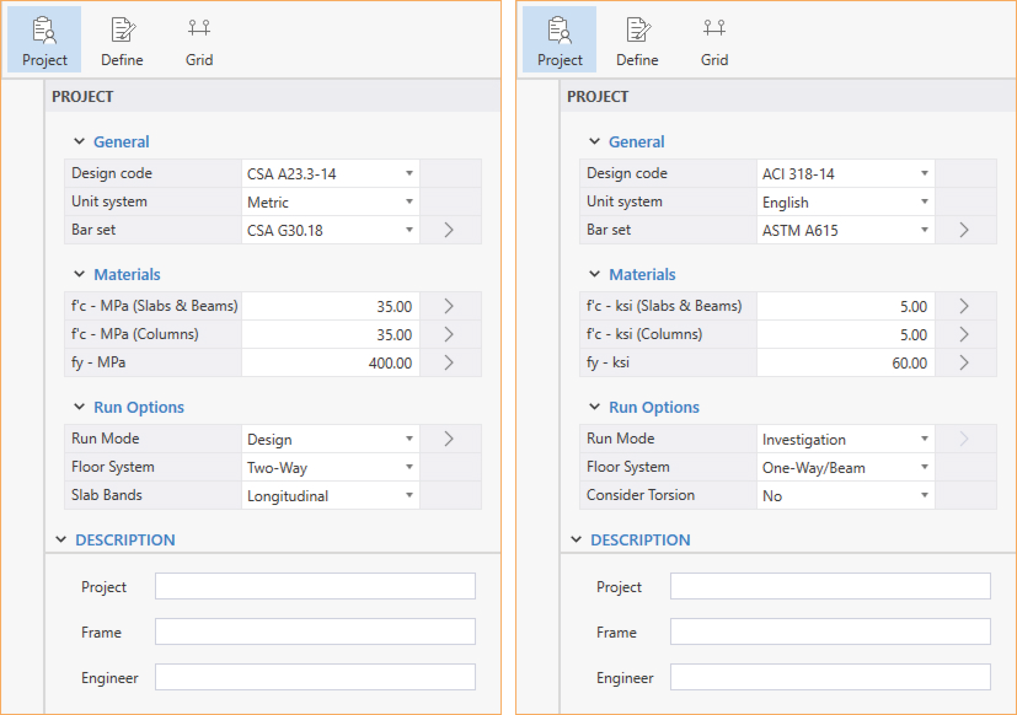
The project information regarding to DESIGN CODE, UNIT SYSTEM, BAR SET, CONCRETE STRENGTH, REINFORCING STEEL STRENGTH, RUN MODE, FLOOR SYSTEM, PROJECT, FRAME, and ENGINEER can be entered into the model through the Project Left Panel. The Program supports American (ACI 318) and Canadian (CSA A23.3) Design Codes, and English and Metric unit systems.
Structural grids must be defined to create a model in spSlab/spBeam. These grids establish the spans and support locations. The spans and supports created by grids then act as placeholders for model elements. Once the spans and supports are set, the user can populate the model with various span elements (slabs, ribs and longitudinal beams/bands) and support elements (columns, capitals, drop panels and transverse beams/bands) to complete the model.
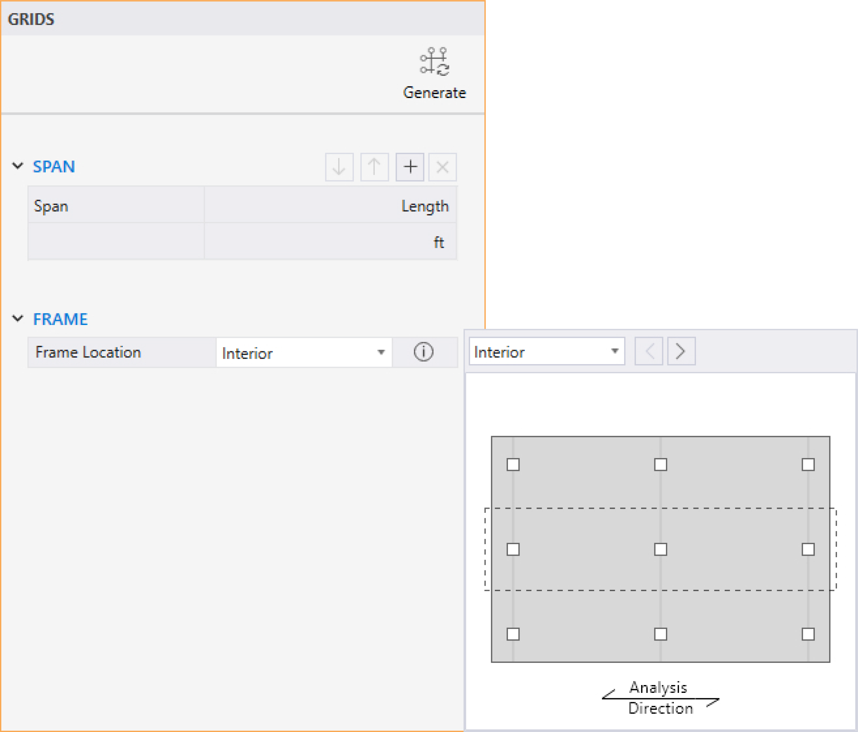
You can select the Grid command button from the Ribbon. The corresponding Grids Left Panel provides various tools and options for effectively working with grids.
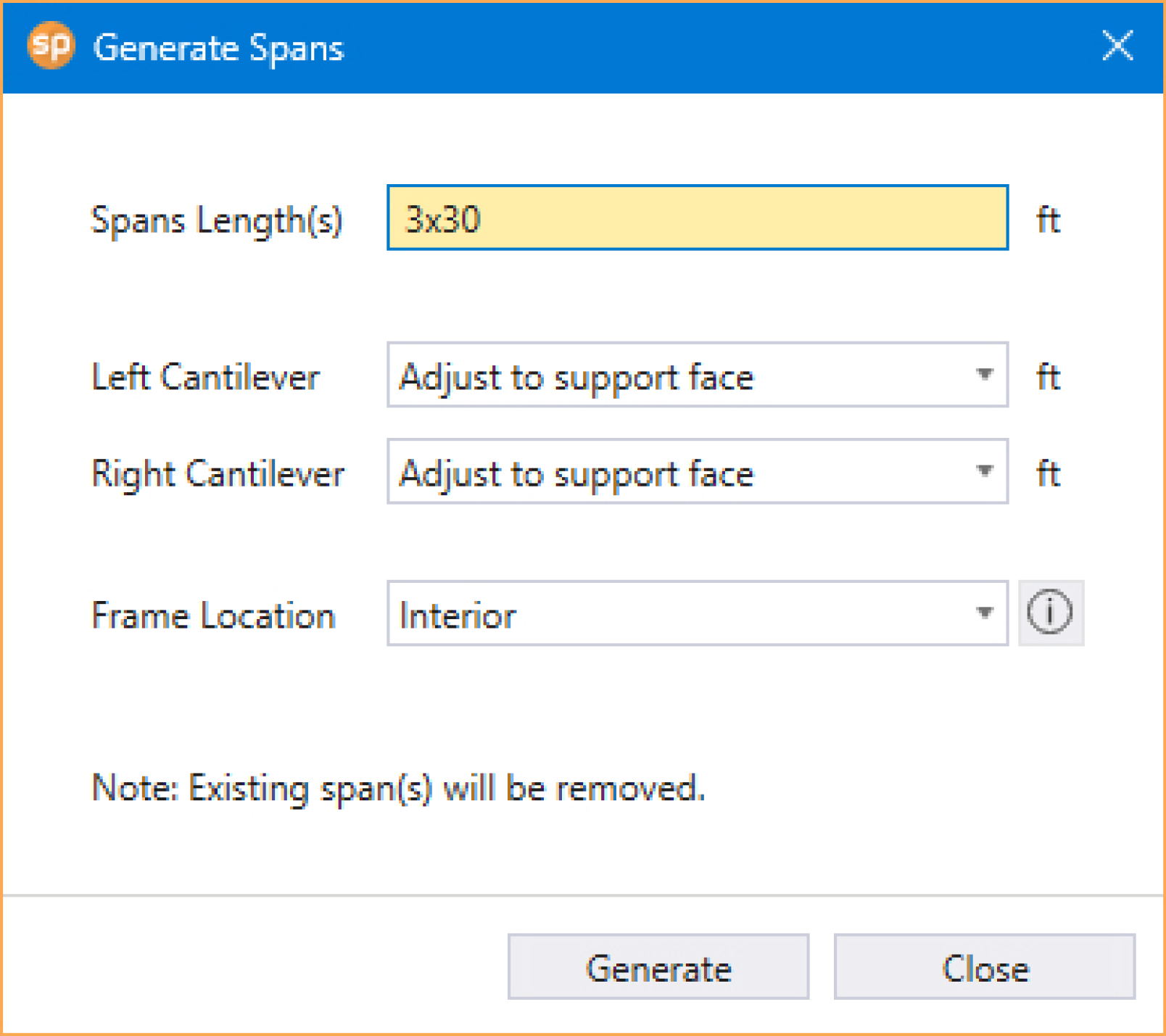
• Click the Generate icon to display the GENERATE SPANS dialog box
• To create multiple spans at once enter:
number of spans x span length in the SPAN LENGTH (S) input box
• You can create spans at different lengths by separating the span lengths by space
• To add cantilevers, select either USER-DEFINED or ADJUST TO SUPPORT FACE in the LEFT CANTILEVER and RIGHT CANTILEVER input boxes
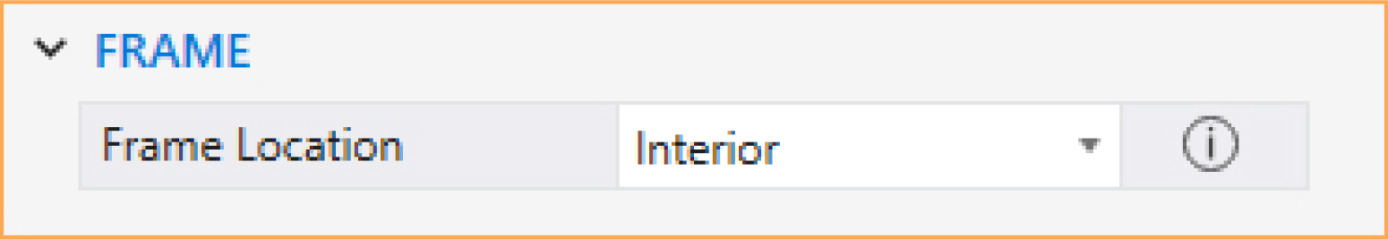
• You can select the frame location from the FRAME LOCATION drop-down list
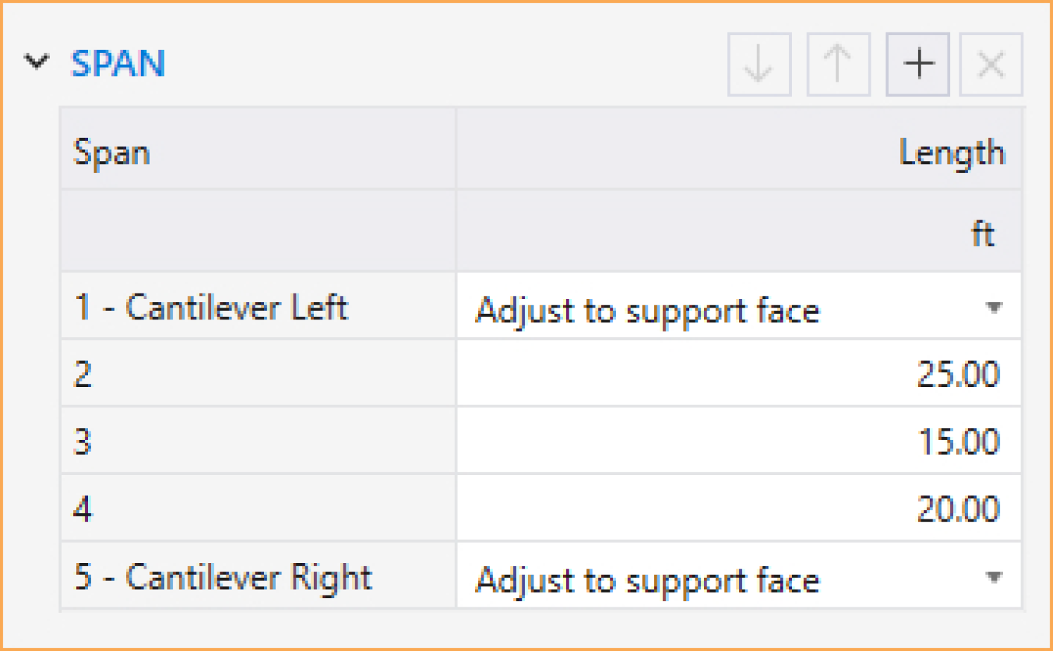
You can use the Span table to change the cantilever options and the LENGTH of the spans. The table can also be used to add or delete specific spans.
• Click on the  button to add a span.
• Click on the  button to delete the selected span in the table.
• Click on the  button to move up the selected span in the table.
• Click on the  button to move down the selected span in the table.
• LENGTH of the span can also be changed by clicking on the respective field and typing in the desired value.
• For cantilevers:
• Select NONE if no cantilever is required.
• Select ADJUST TO SUPPORT FACE to extend the span to the support face.
• Select USER-DEFINED to manually specify the cantilever length.
5.2.2.4. Working with Frame Location
You can select the span location from the FRAME LOCATION drop-down list.
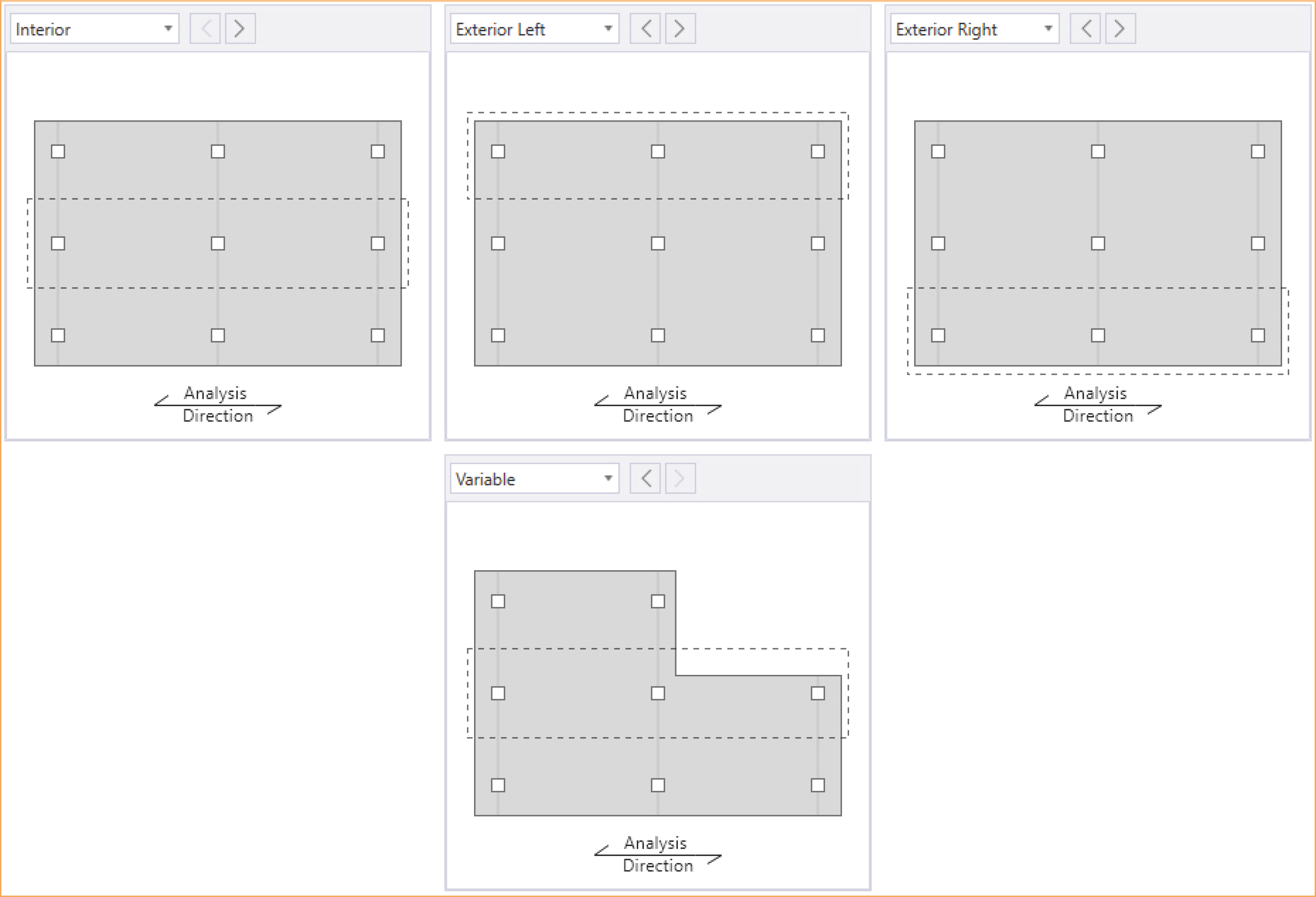
Three types of locations are available: INTERIOR, EXTERIOR LEFT and EXTERIOR RIGHT. If the frame being analyzed has more than one of the above-mentioned locations, then VARIABLE can be selected and the individual span locations provided accordingly. The "left" and "right" are defined as you look along the direction of analysis. If a span has design strips on both sides, it should be an "INTERIOR" span. If a span has only a left design strip, it should be an "EXTERIOR RIGHT" span. If a span has only a right design strip, it should be an "EXTERIOR LEFT" span.
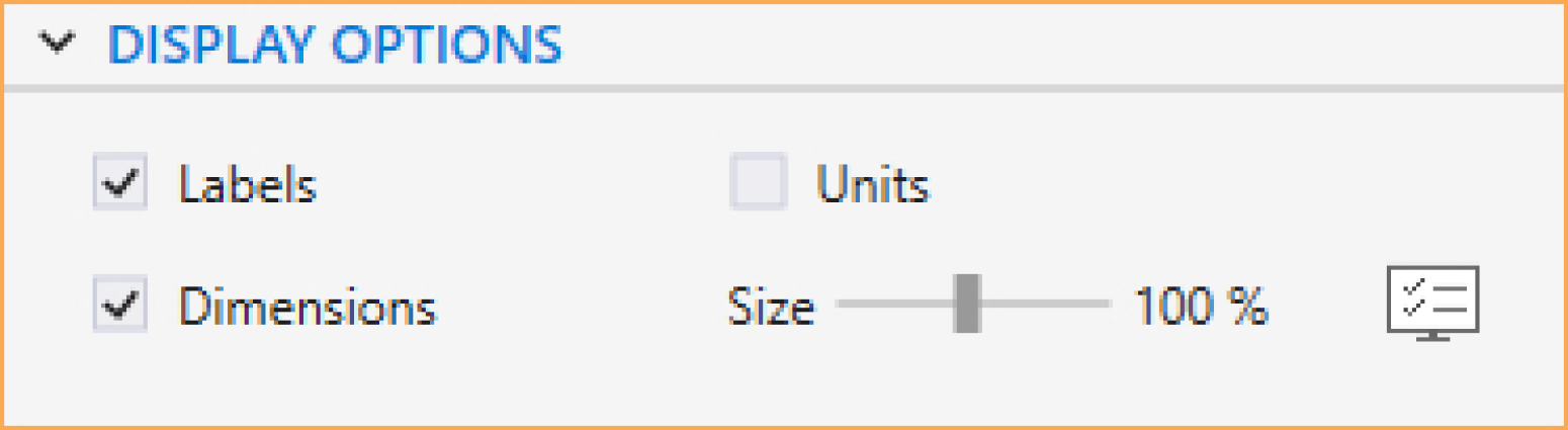
• Use the checkboxes to toggle the display of various grid items in the model.
• You can use the slider to adjust the SIZE of the grid LABELS, UNITS and DIMENSIONS displayed.
The DEFINITIONS dialog box contains four categories: Materials, Reinforcement Criteria, Design and Modeling Options, and Load Case/Combo. You can access this dialog box by selecting the Define command from the Ribbon.
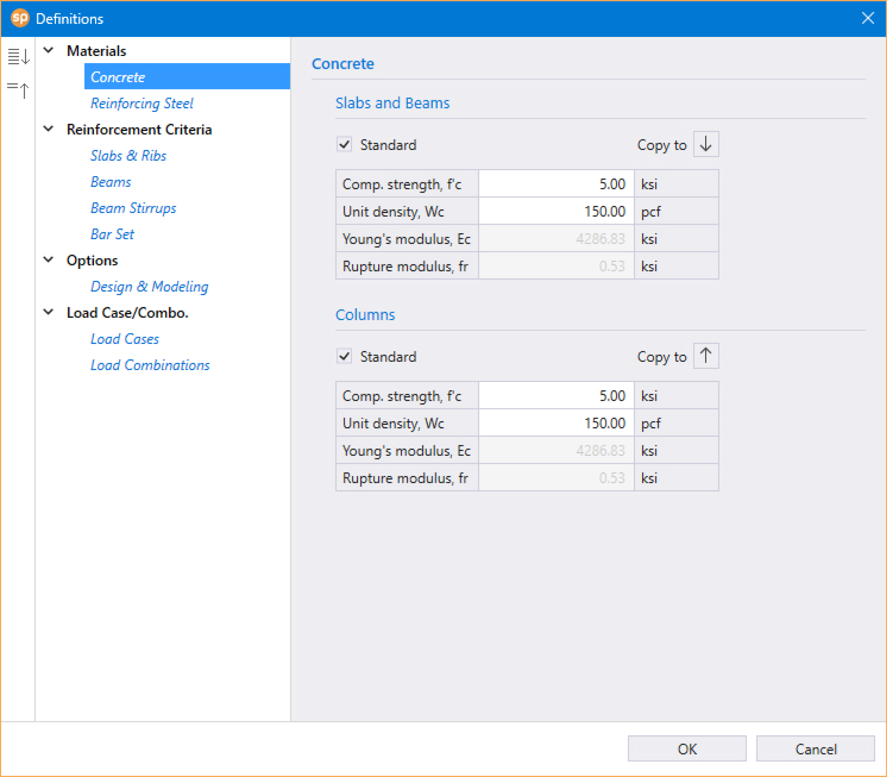
The Materials that can be defined are: Concrete and Reinforcing Steel.
The following properties for slab, beam, and column concrete, are entered by the user:
• COMPRESSIVE STRENGTH, f'c, and
• UNIT DENSITY, Wc
Other concrete properties:
• YOUNG’S MODULUS, Ec, and
• RUPTURE MODULUS, fr
are automatically computed and displayed when STANDARD option is selected. The user can manually modify any of the values by deselecting the option.
When STANDARD option is selected, Design Code mandated default values for the young’s modulus, Ec, and the rupture modulus, fr, for the slabs, beams, and columns are computed automatically and are based on f'c and λ where λ is function of Wc. The modulus of rupture is used to determine the cracking moment when computing the effective moment of inertia in deflection calculations. Refer to Section 2.2.1.2 for default Ec, and fr equations per ACI 318 and CSA A23.3 Design Codes. Unchecking the STANDARD option shall enable the User to input Ec and fr manually that deviates from Equations in Section 2.2.1.2. Therefore, it may lead to an output not in compliance with ACI 318 and CSA A23.3 if used without sound Engineering Judgment.
If precast concrete is used, check PRECAST CONCRETE checkbox1.
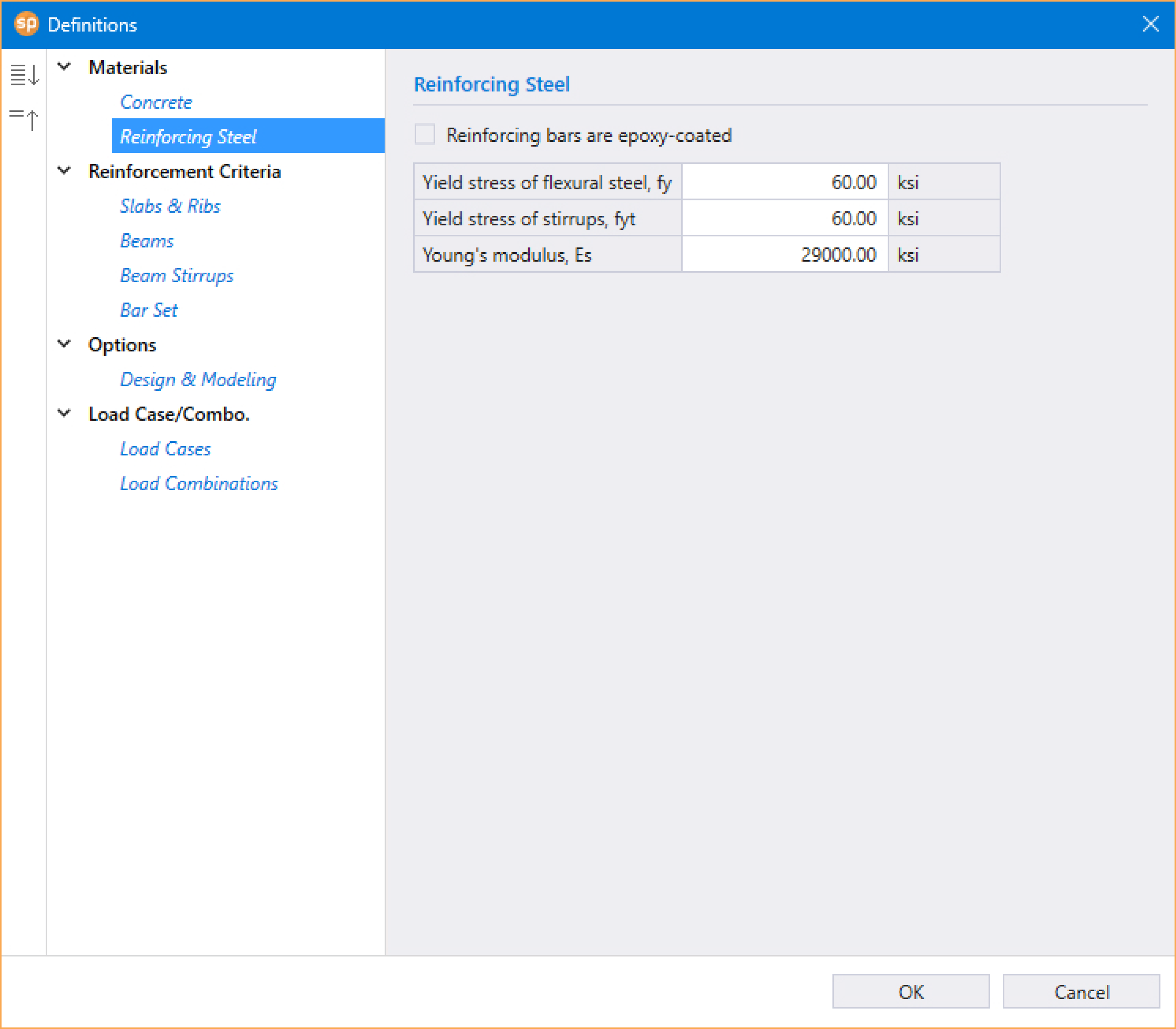
The following properties are entered by the user.
• YIELD STRESS OF FLEXURAL STEEL, fy
• YIELD STRESS OF STIRRUPS, fyt
• YOUNG’S MODULUS, Es
• If reinforcement is epoxy-coated, check REINFORCING BARS ARE EPOXY-COATED checkbox. This selection affects development lengths.
5.2.3.2. Reinforcement Criteria
The Reinforcement Criteria that can be defined are for: Slabs & Ribs, Beams, Beam Stirrups, and Bar Set.
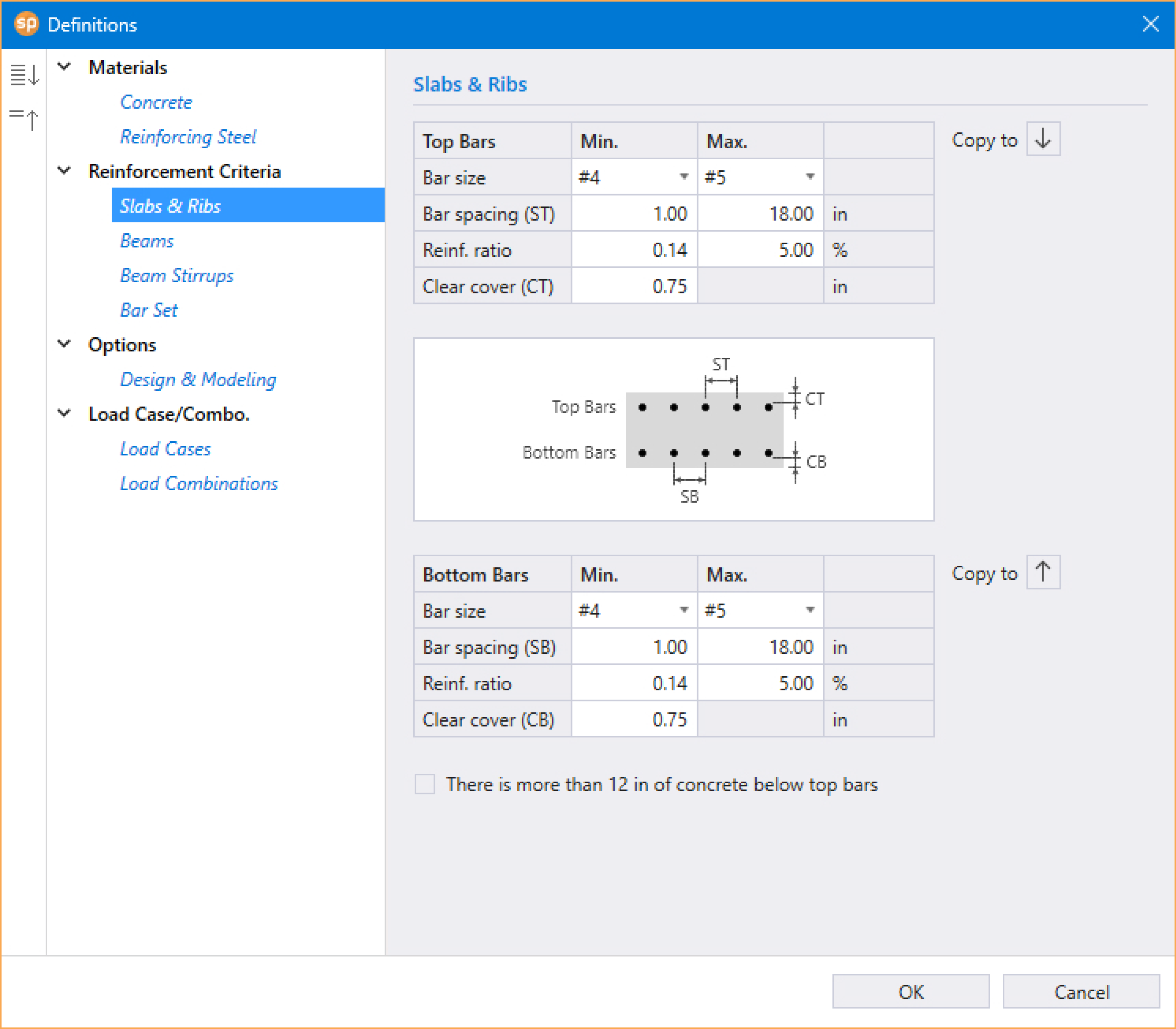
To define Reinforcement Criteria for Slab and Ribs:
• Enter the minimum bar size to start the iteration for determining flexural reinforcement.
• Enter the maximum bar size. This number will be used as a stop in the iteration for determining flexural bars in beams.
• Enter minimum bar spacing for slab and rib flexural reinforcement. This number should be based on aggregate size or detailing considerations. Default spacing is 1 in. [30 mm] for slabs and ribs.
• Enter maximum bar spacing for slab and rib flexural reinforcement. Default spacing is 18 in. [450 mm] for slabs and ribs.
• Enter minimum Reinforcement Ratio for slab and rib flexural reinforcement. Default ratio is 0.14% [0.14%] for slabs and ribs. If the user specified value is smaller than 0.14%, 0.14% is used by spSlab. If the user specified value is greater than 0.14%, the specified value is used by spSlab.
• Enter maximum Reinforcement Ratio for slab and rib flexural reinforcement. Default ratio is 5% for slabs and ribs.
• Enter the clear covers for top and bottom reinforcing bars. For the top reinforcement, this distance is from the top of the slab to the top of the top bars. For the bottom reinforcement, this distance is from the bottom of the slab to the bottom of the bottom bars (see Figure 5.1). The default value is 0.75 in. [20 mm] for both input items.
• If the top bars have more than 12 in. [300 mm] of concrete below them, check the corresponding check box.
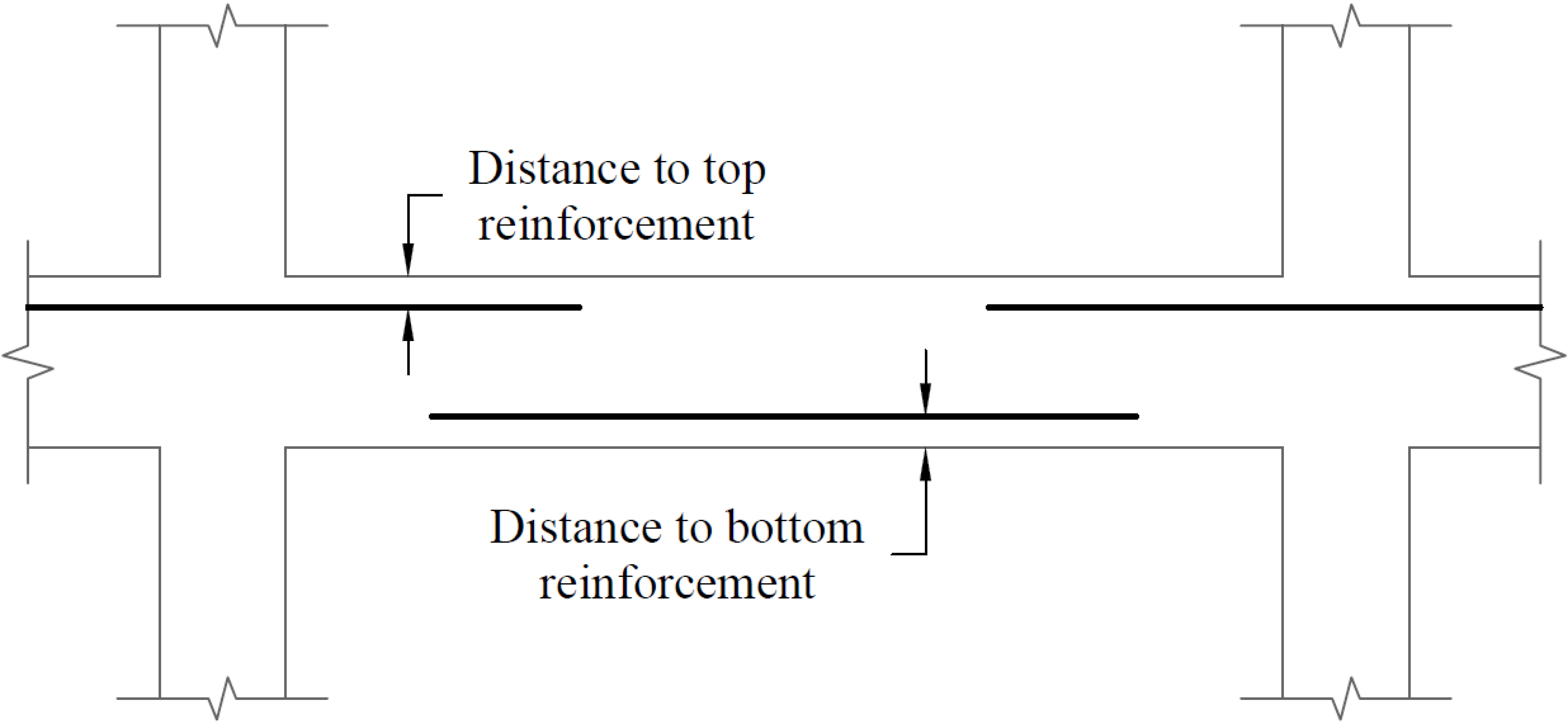
Figure 5.1 - Clear Cover to Reinforcement
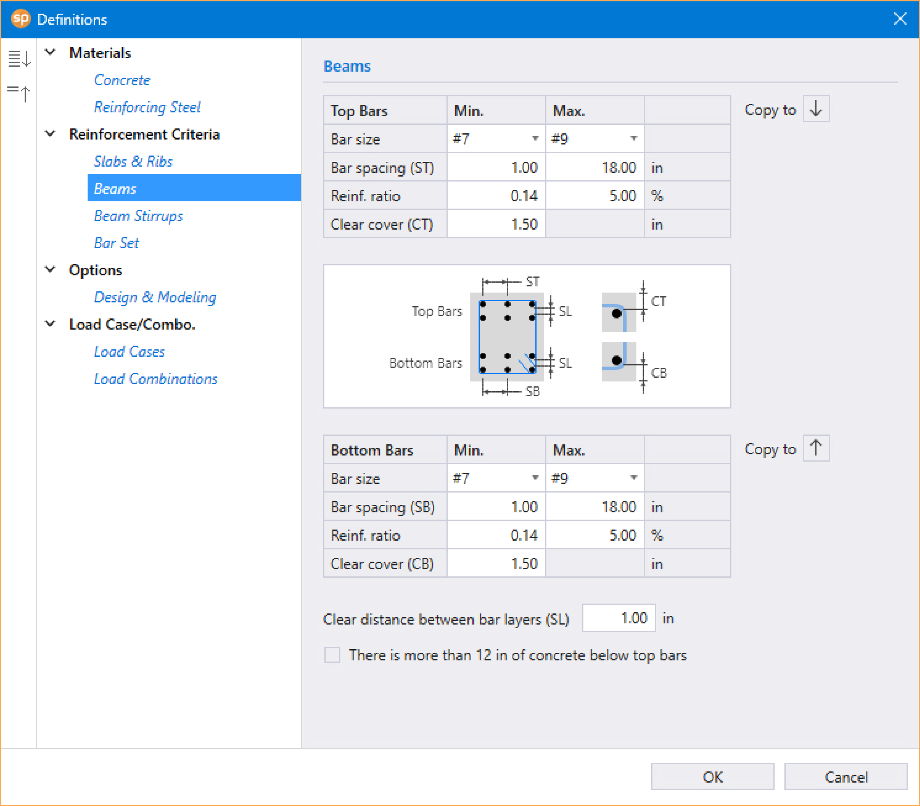
To define Reinforcement Criteria for Beams:
• Enter the minimum bar size for top and bottom bars to start the iteration for determining flexural reinforcement.
• Enter the maximum bar size for top and bottom bars. This number will be used as a stop in the iteration for determining flexural bars in beams.
• Enter the minimum bar spacing for beam flexural reinforcement. This number should be based on aggregate size or detailing considerations. The default minimum reinforcement bar spacing is 1 in. [30 mm].
• Enter the maximum bar spacing for beam flexural reinforcement. The default maximum reinforcement spacing is 18 in. [450 mm].
• Enter the minimum Reinforcement Ratio for beam flexural reinforcement. Default ratio is 0.14% [0.14%] for beams. If the user specified value is smaller than 0.14%, 0.14% is used by spSlab. If the user specified value is greater than 0.14%, the specified value is used by spSlab.
• Enter the maximum Reinforcement Ratio for beam flexural reinforcement. Default ratio is 5% for beams.
• Enter the covers for top and bottom reinforcing bars for beams. For the top reinforcement, this distance is from the top of the beam to the top of the top bars; and for the bottom reinforcement, this distance is from the bottom of the beam to the bottom of the bottom bars (see Figure 5.1). The default value is 1.5 in. [30 mm] for both input items.
• Enter the clear distance between bar layers to use if the program needs to distribute flexural bars in multiple layers. Default distance is 1 in. [30 mm] for beams.
• If the top bars have more than 12 in. [300 mm] of concrete below them, check the corresponding check box.
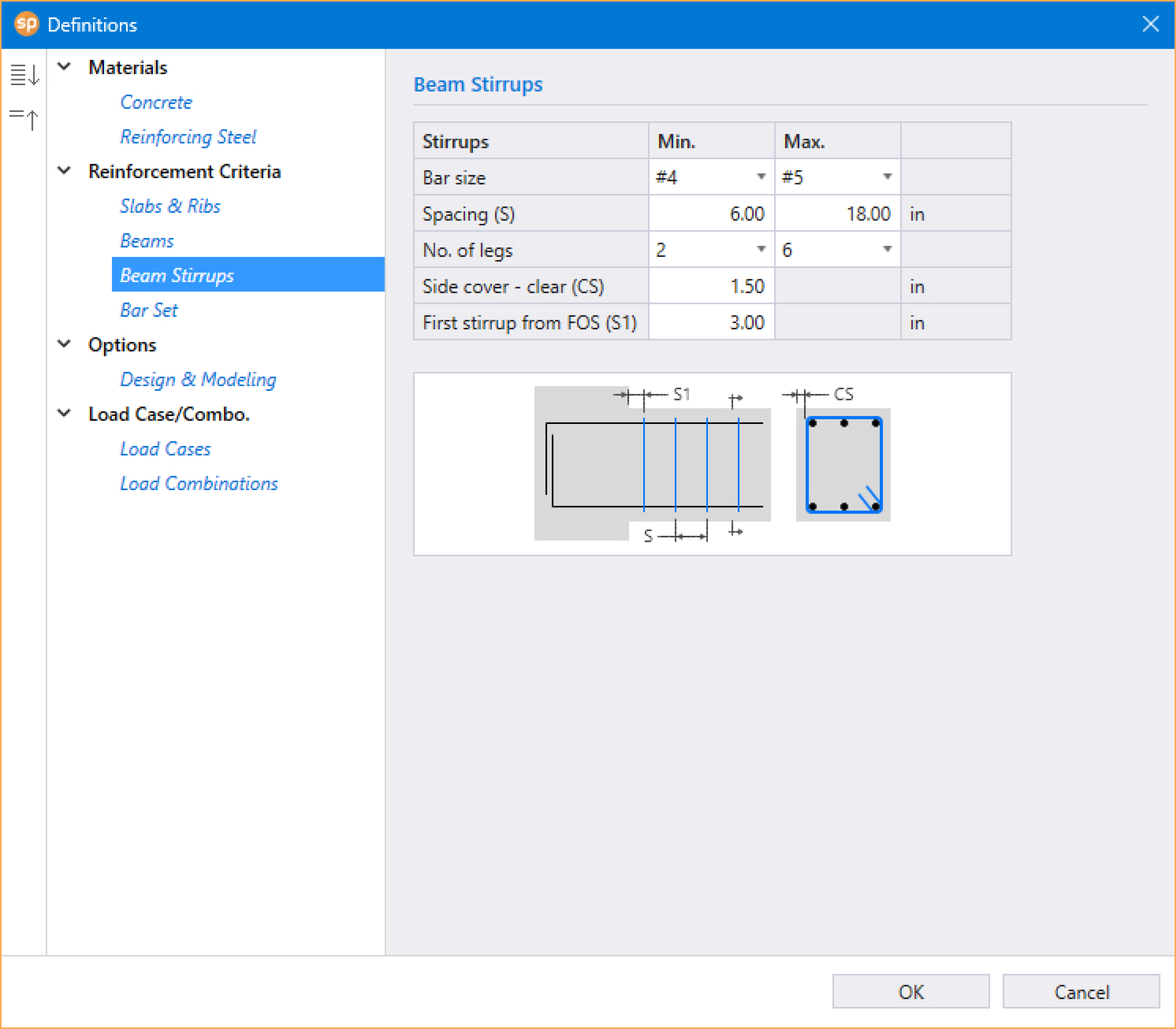
To define Reinforcement Criteria for Beam Stirrups:
• Enter the minimum bar size for stirrups to start the iteration for determining shear reinforcement.
• Enter the maximum bar size for stirrups. This number will be used as a stop in the iteration for determining shear reinforcement in beams.
• Enter the minimum spacing for stirrups. This number should be based on aggregate size or detailing considerations. The default stirrup spacing is 6 in. [150 mm].
• Enter the maximum spacing for stirrups. The default maximum stirrup spacing is 18 in. [450 mm].
• Enter the side cover which is measured from the side face of a beam to the face of the stirrup (see Figure 2.28). The default value is 1.5 in. [30 mm].
• Enter the distance from face of support (FOS) to first stirrup. The default value is 3.0 in [75 mm].
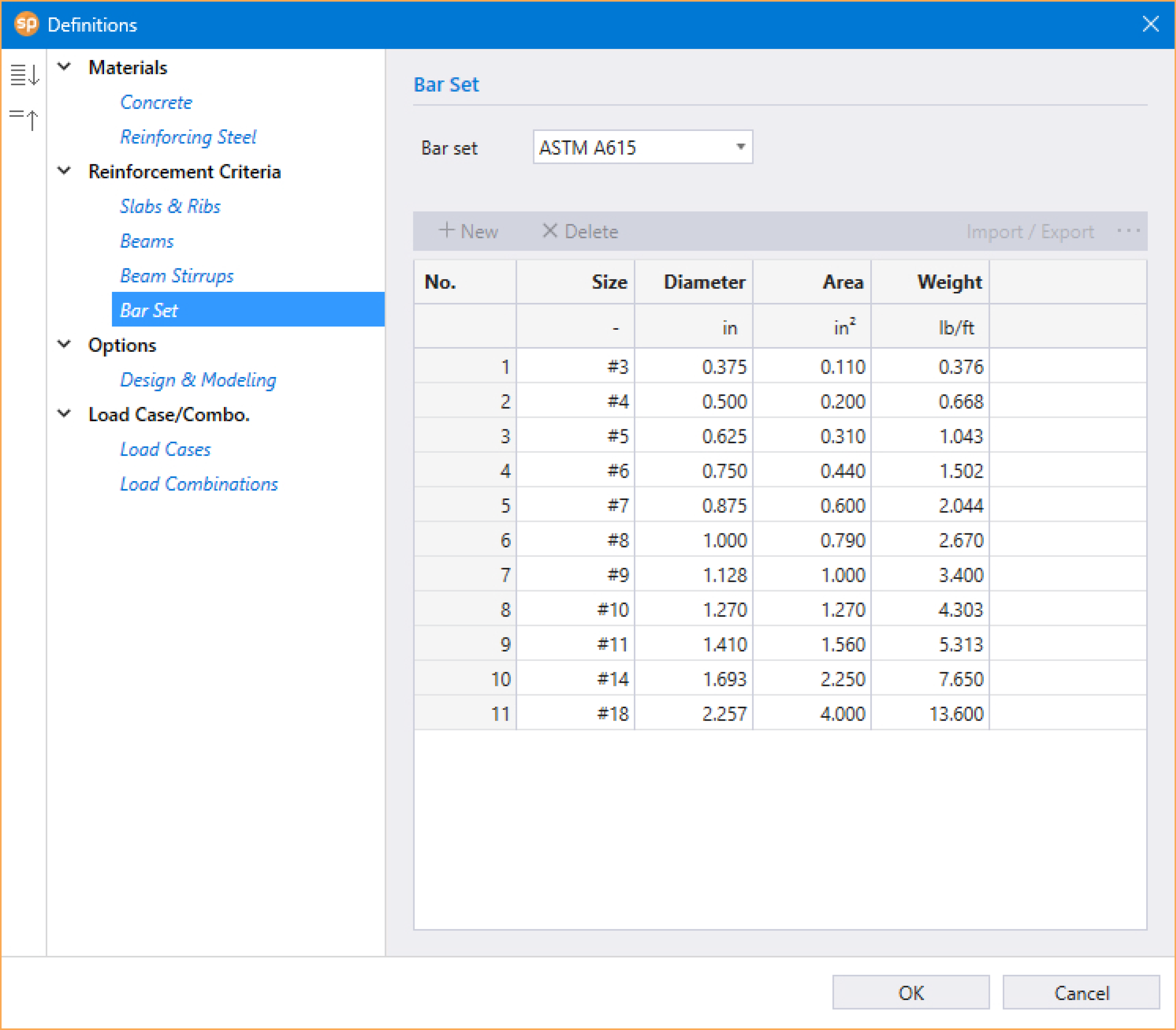
The Bar Set can be selected from pre-defined standard sets or can be USER-DEFINED. For a new USER-DEFINED set entry, the SIZE, DIAMETER, AREA and WEIGHT of the bar are required. USER-DEFINED set can also be imported or exported.
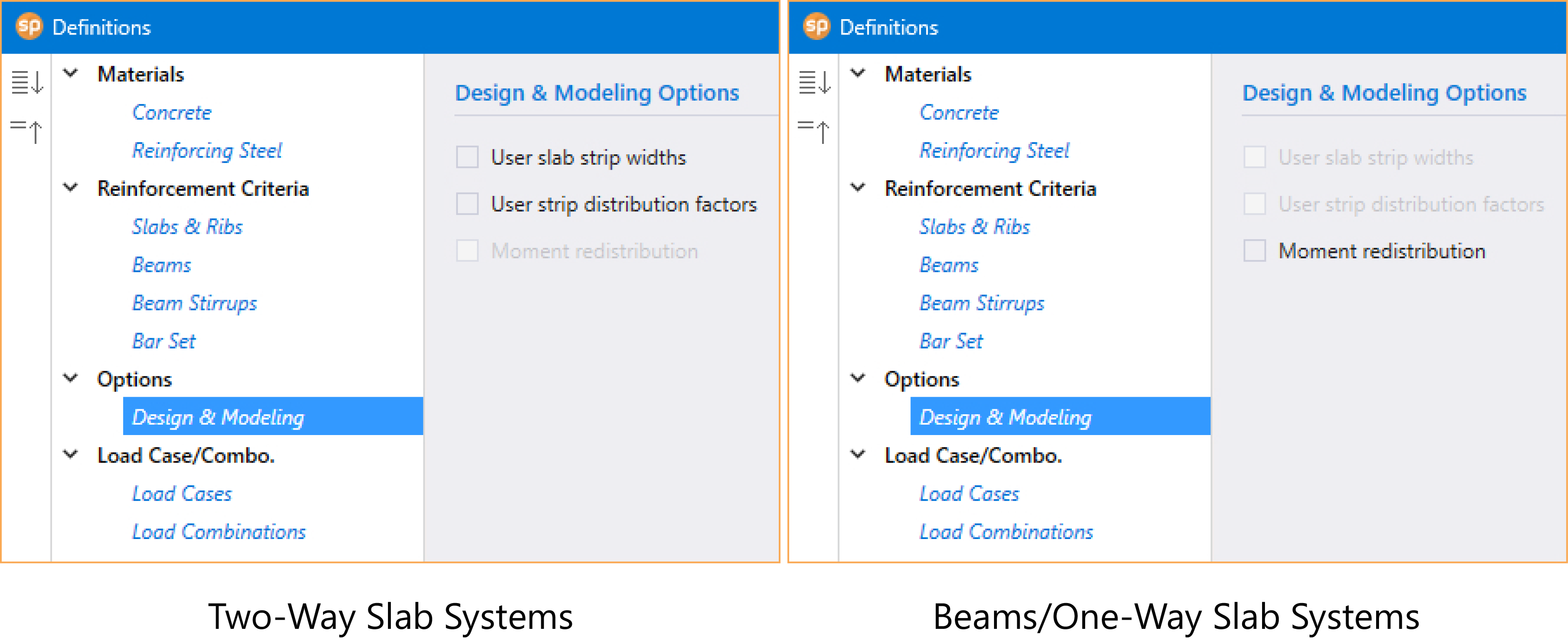
To specify Design & Modeling Options for two-way systems:
• Check USER SLAB STRIP WIDTHS to enable manual input of column strip width. The default values are calculated according to design code selected. The validity of the assumptions when entering user defined values are to be decided by the Designer.
• Check USER STRIP DISTRIBUTION FACTORS to enable manual input of moment distribution factors. The default values are calculated according to design code selected. The validity of the assumptions when entering user defined values are to be decided by the Designer.
To specify Design & Modeling Options for beams/one-way slab systems:
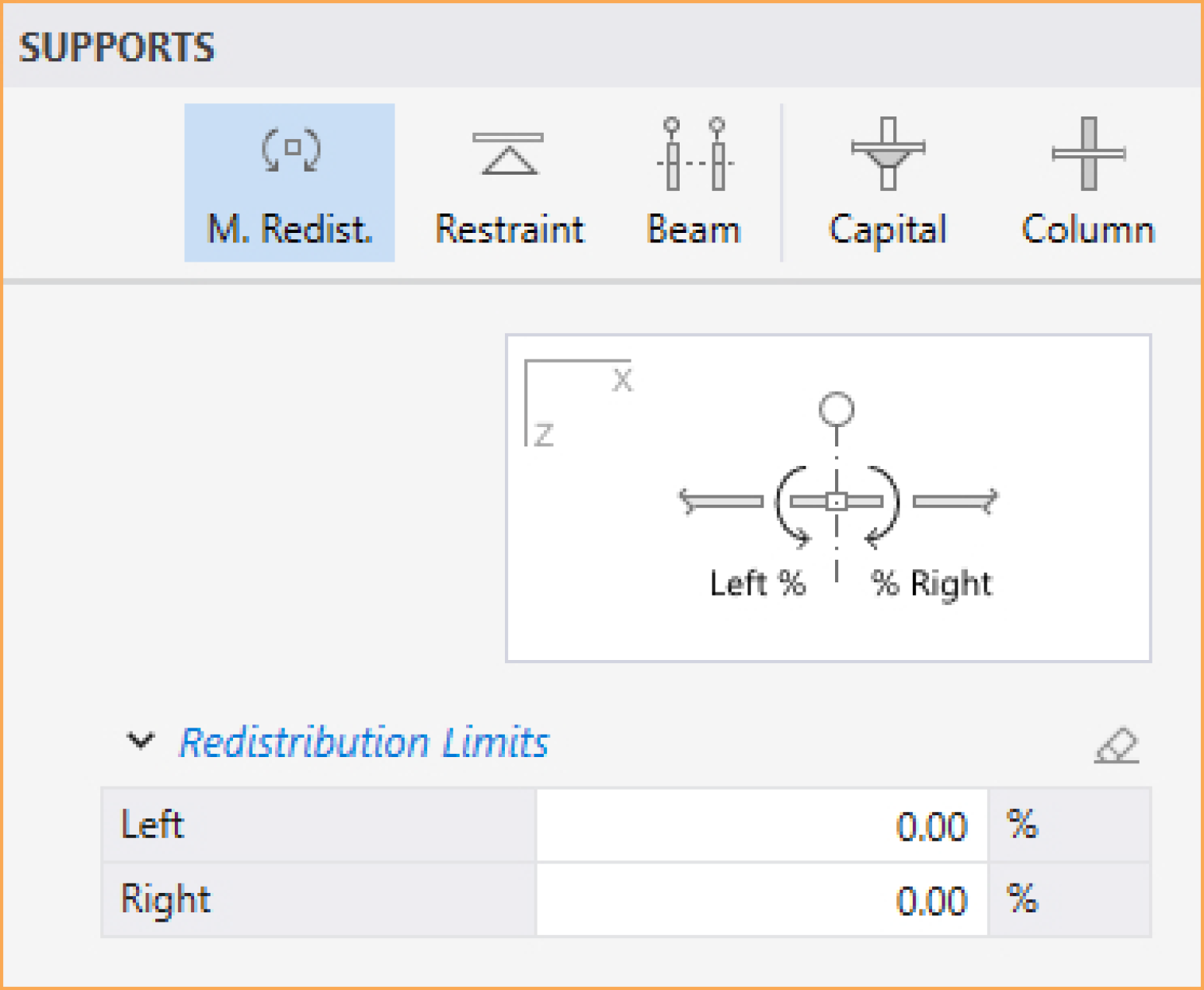
• Check MOMENT REDISTRIBUTION checkbox if it is to be considered in the analysis. This option has to be checked for the Moment Redistribution tab to be available in the Supports command.
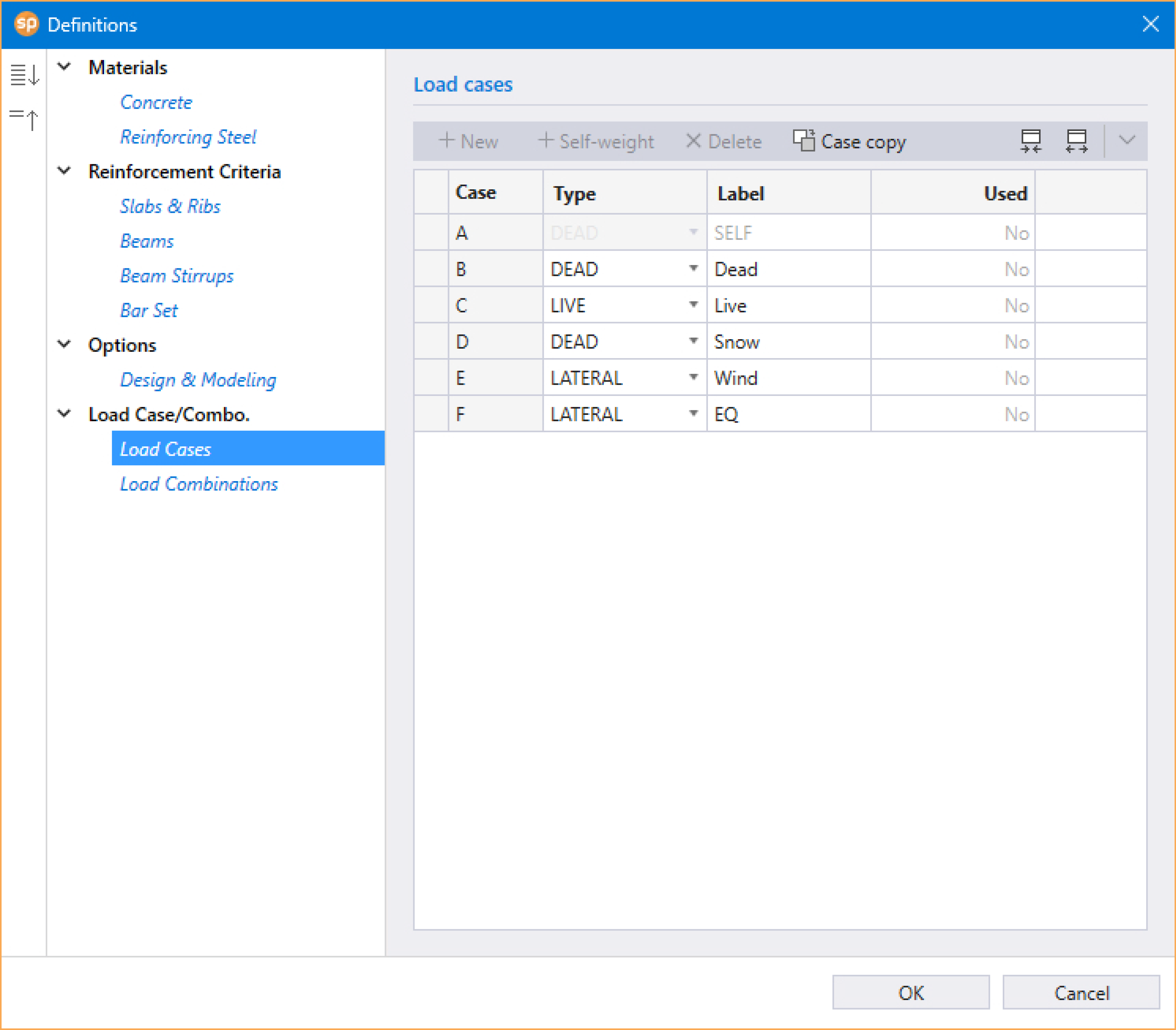
The Load Case / Combo. that can be defined are: Load Cases and Load Combinations.
The Load Cases definition consists of the CASE, TYPE, LABEL, and whether the Load Cases is USED in the model or not.
Up to 6 load cases of dead load, live load or lateral load can be defined in the Load Cases dialog box. The default five load case labels (types) are SELF (dead load), Dead (dead load), Live (live load), Wind (wind load), and EQ (seismic load). Once the maximum number is reached, the NEW button will be disabled.
Note: Only one case of live load can be defined. Load case label must be unique for each of the load cases. To ignore self-weight in both strength and deflection calculations remove load case SELF from the list of load cases.
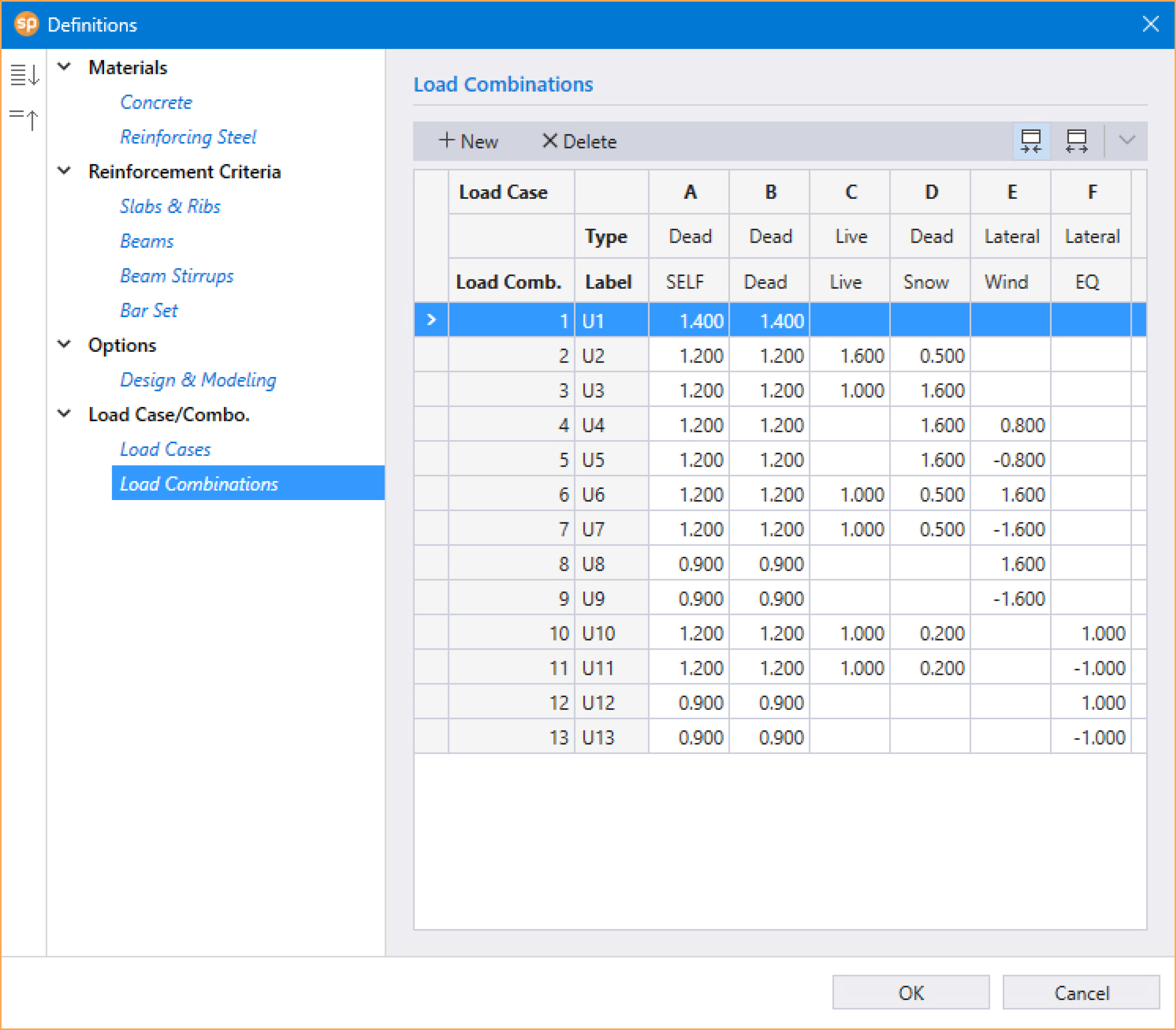
The Load Combinations definition consists of the LOAD CASES, LOAD CASE TYPE, LOAD COMBINATION NUMBER, LOAD COMBINATION LABEL, and LOAD FACTORS.
Up to fifty load combinations may be defined. All the combinations are indexed automatically from U1 to U50.
In spSlab The Elements that can be created are: Slabs, Longitudinal Beams/Bands, Ribs, Columns, Drop Panels, Column Capitals and Transverse Beams/Bands.
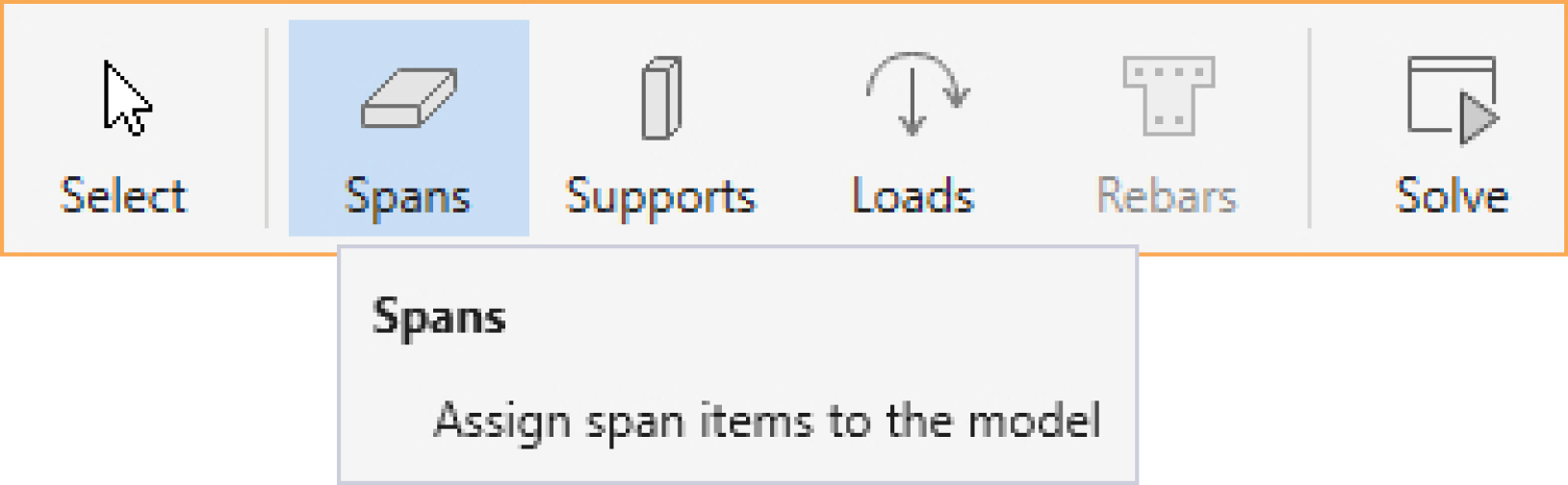
You can create Spans Elements using the Spans command from the Ribbon.
You can create Slabs, Longitudinal Beams and Ribs by using one of the following three tools in the Spans Left Panel.
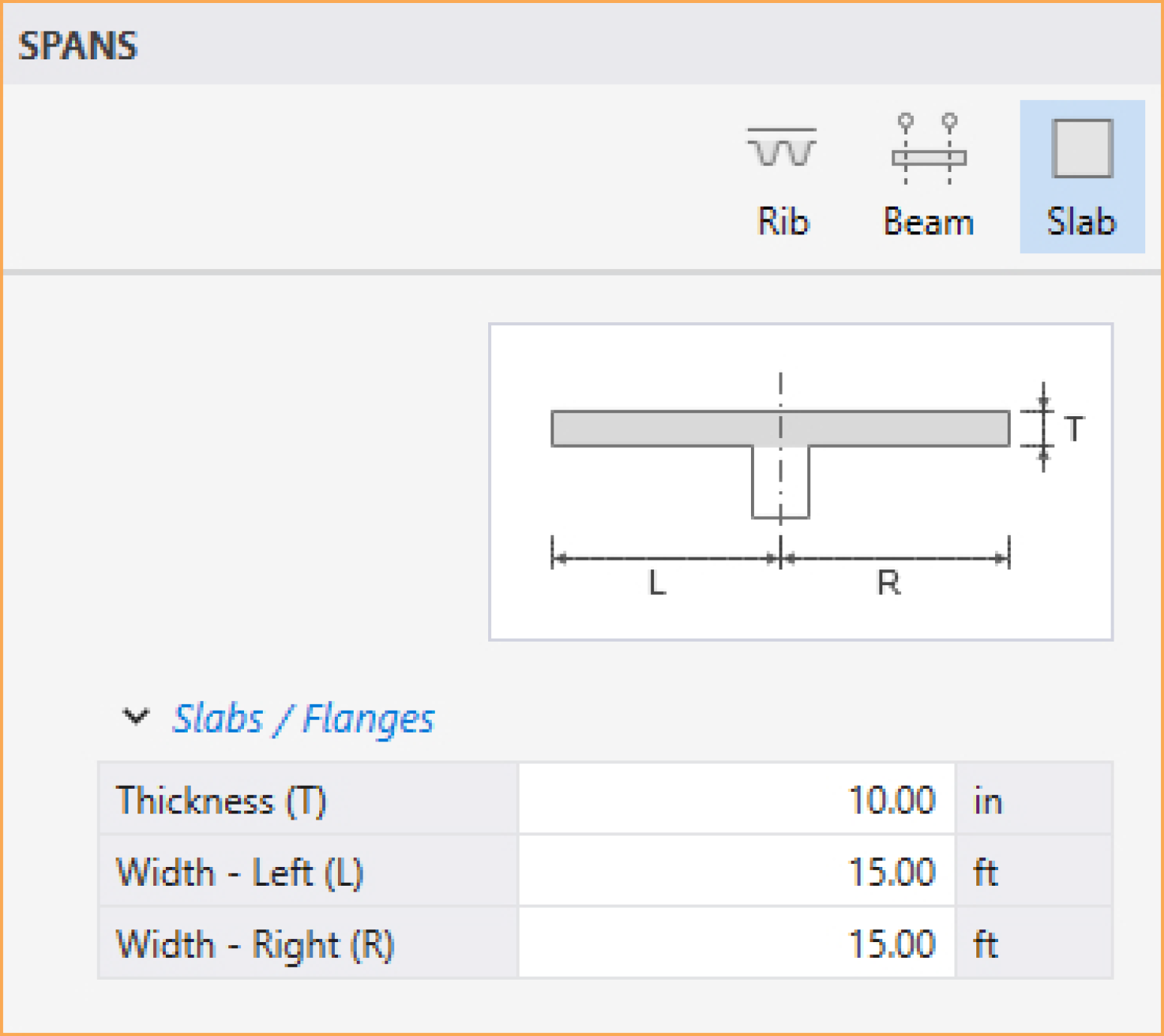
You can enter the slab THICKNESS, WIDTH – LEFT, and WIDTH – RIGHT data in the Left Panel. Then click on the desired span (or drag over multiple spans) to assign the slab.
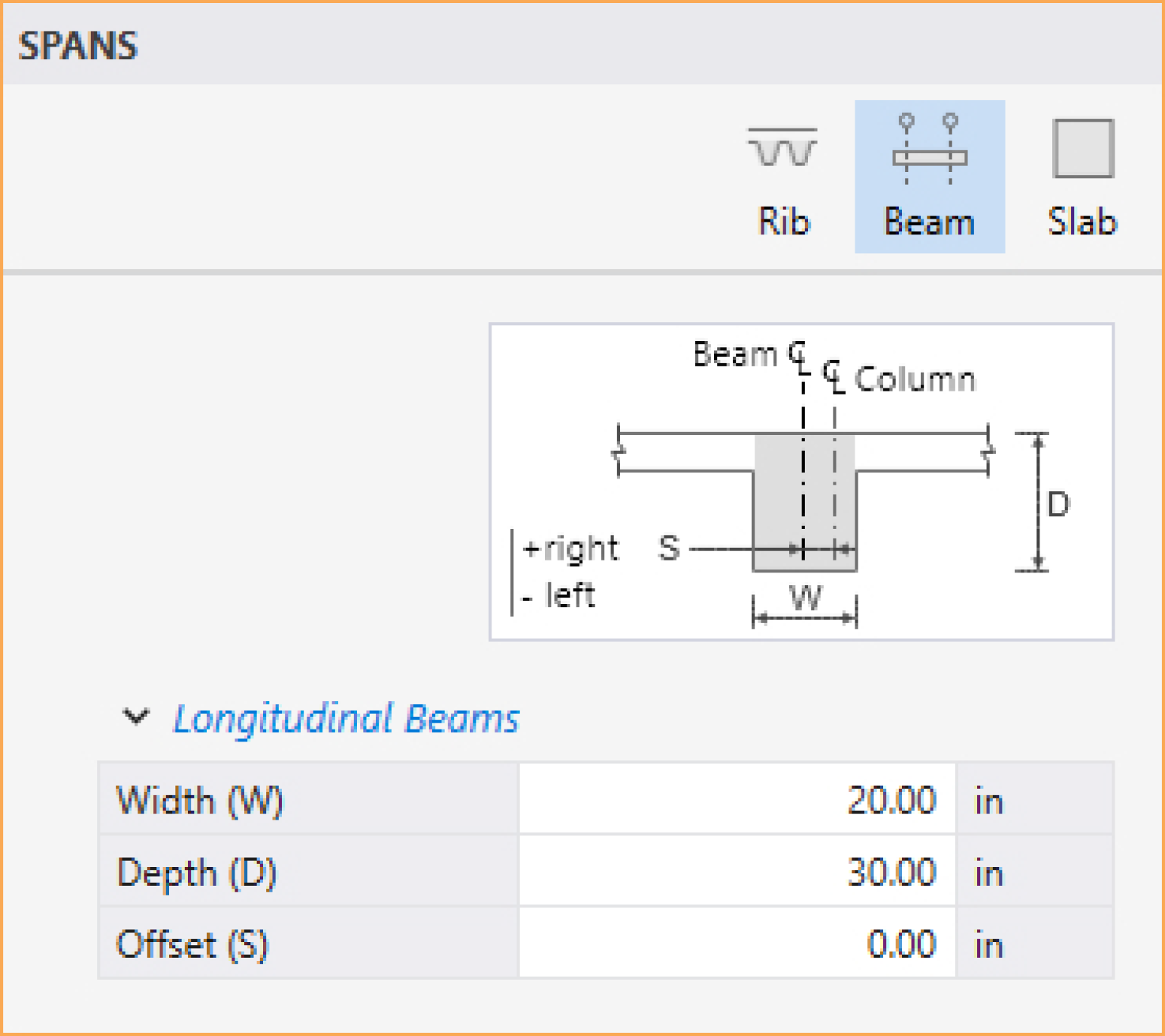
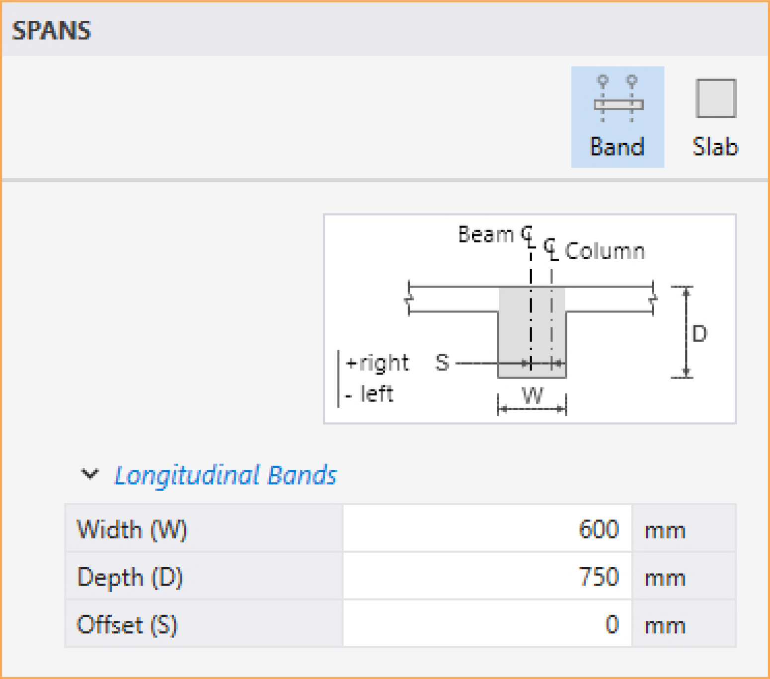
You can enter the beam WIDTH, DEPTH, and OFFSET data in the Left Panel. Then click on the desired span (or drag over multiple spans) to assign the beam.
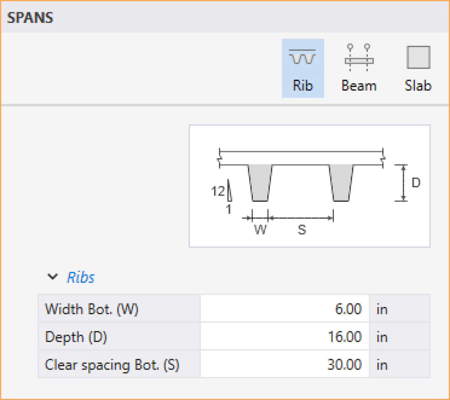
For joist systems, you must define the rib geometry. The ribs are assumed to be the same throughout the strip.
You can enter the rib WIDTH BOTTOM, DEPTH, and CLEAR SPACING BOTTOM data in the Left Panel. Then click on the desired span (or drag over multiple spans) to assign the ribs.
Longitudinal slab bands are only available for two-way floor systems when LONGITUDINAL is selected for Slab Bands under Run Options in Project Left Panel (CSA A23.3-14/04 only).
You can enter the slab band WIDTH, DEPTH, and OFFSET data in the Left Panel. Then click on the desired span (or drag over multiple spans) to assign the slab band.
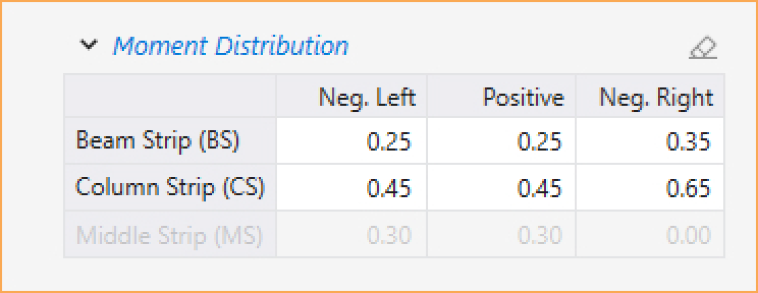
Strip Moment Distribution Factors
User has the ability to manually adjust strip moment distribution factors for two-way floor systems when USER STRIP DISTRIBUTION FACTORS option is checked in the Design & Modeling Options under the Define command. However, in spSlab v10.00, strip distribution factor is a select only property. For details on how to assign or edit these factors, refer to Editing Model Elements Using the Left Panel section. In such case, the strip Moment Distribution table will become available under Spans Left Panel when the Select command button is toggled on. This table contains fields for inputting distribution factors in column and beam strips. The distribution factors for middle strip are recalculated internally.
5.2.4.2. Supports Elements
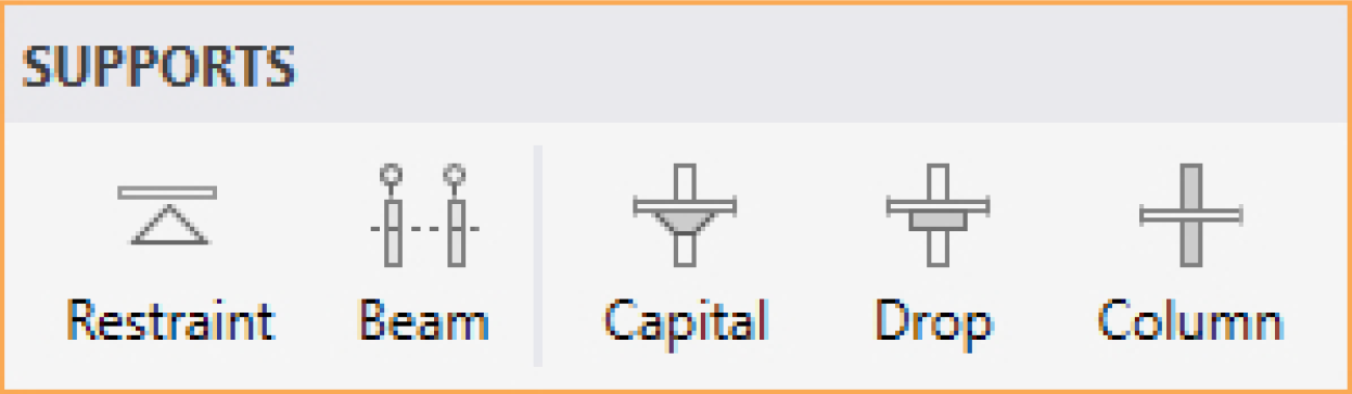
You can create Supports Elements using the Supports command from the Ribbon.
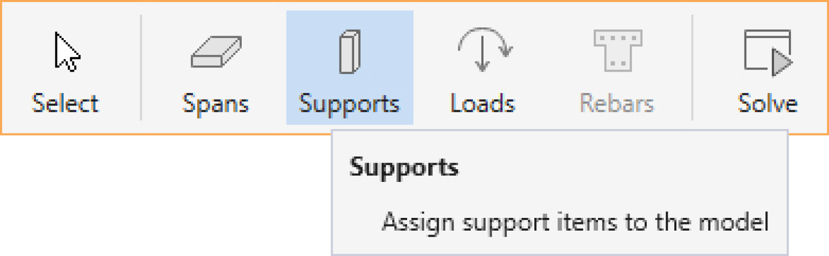
You can create Columns, Drop Panels, column Capitals, Transverse Beams, and Restraints by using one of the following tools in the Supports Left Panel.
Column data is optional. If no column is specified at the supports, the support is assumed pinned.
You can enter the COLUMN ABOVE, COLUMN BELOW, and COLUMN OPTIONS data in the Left Panel. Then click on the desired support (or drag over multiple supports) to assign the column.
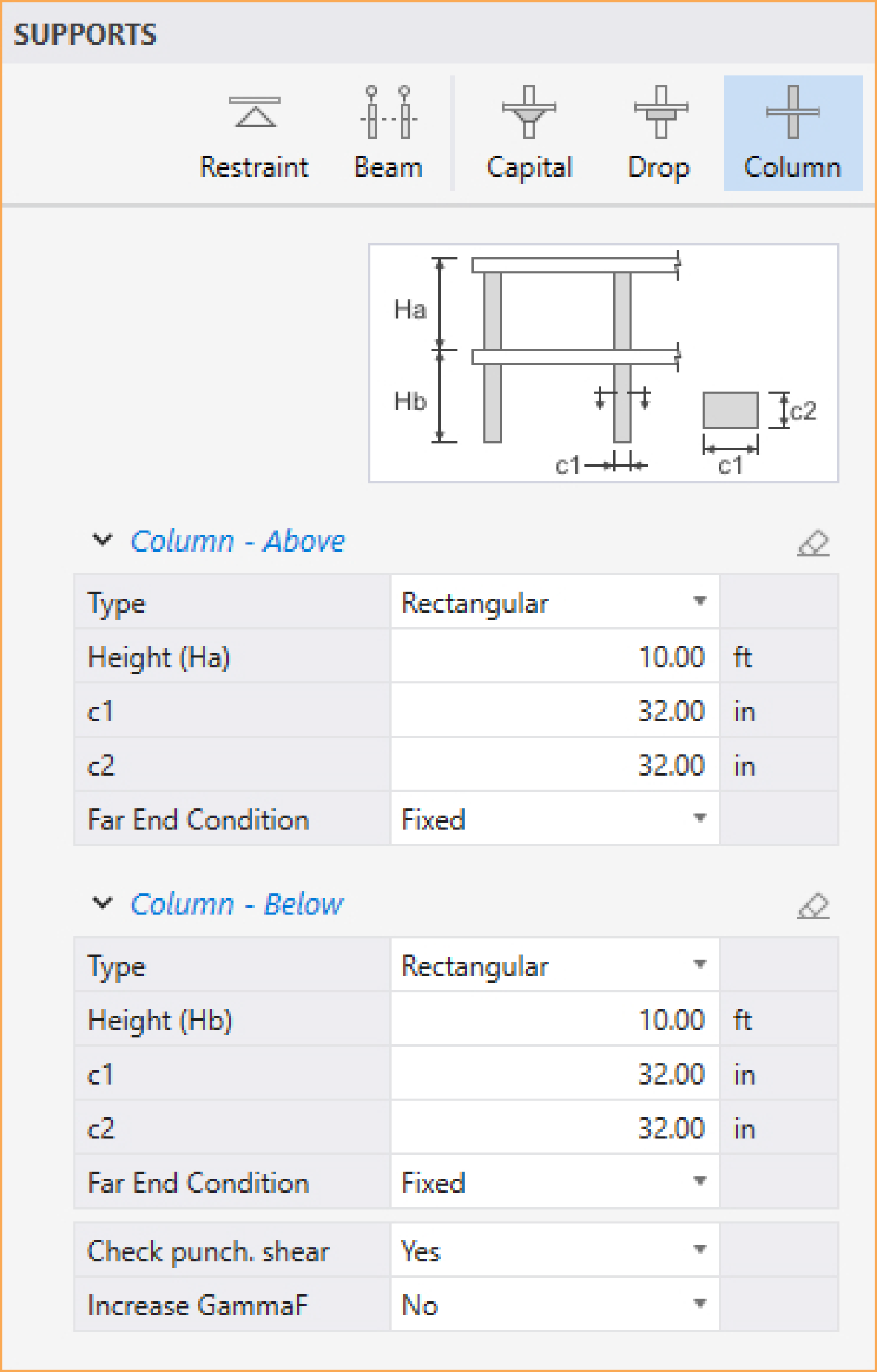
More information about columns FAR END CONDITION can be found in the Restraint section.
Drops are available for the flat slab or waffle slab systems and can be defined at all the support locations.
You can enter the TYPE, THICKNESS, and CHECK PUNCHING SHEAR data in the Left Panel. Then click on the desired support (or drag over multiple supports) to assign the drop panel.
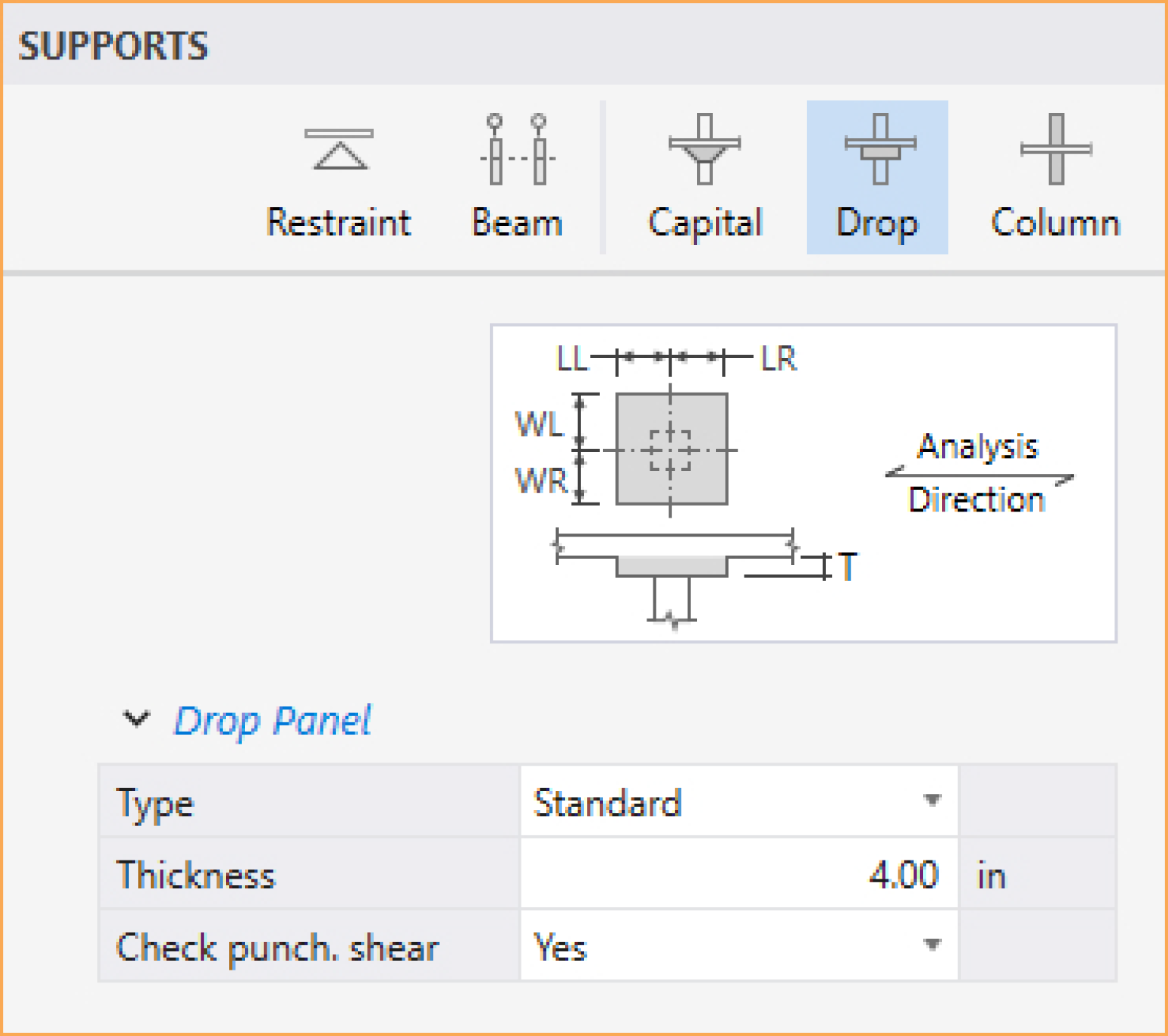
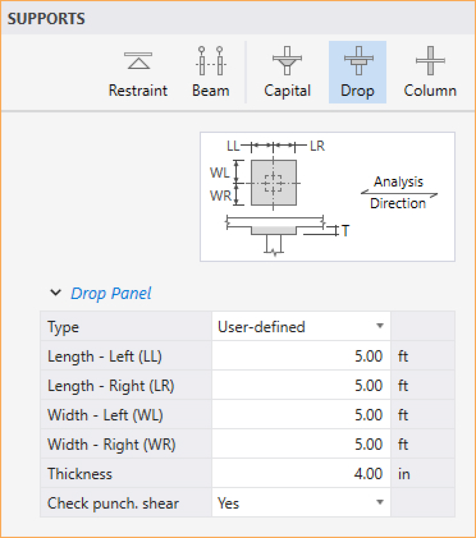
If spSlab is to compute the drop dimensions, the STANDARD option should be selected from the TYPE drop-down list and then only the drop depth will be available. When the STANDARD drop option is selected, spSlab will calculate drop panel dimensions in accordance with ACI 3182. Similar requirements contained in previous editions of the CSA A23.3 Standard have been removed from the 1994 edition. As a result, the ACI minimum specifications for drop panels are also used in CSA A23.3 runs when the STANDARD drop option is selected. If you would like to specify drop dimensions other than those computed by spSlab, you must select USER-DEFINED from the TYPE drop-down list.
Enter the dimension in the direction of analysis from the column centerline to the edge of the drop left of the column (see Figure 5.2). If this is a STANDARD drop, this dimension will not be available and the length left is set equal to the slab span length left/6 for interior columns or the left cantilever length for the first column.
Enter the width dimension in the transverse direction (see Figure 5.2). If this is a STANDARD drop, this dimension will not be available and the width is set equal to slab width/3.
In order for spSlab to recognize drops, drop thickness are required for the flat slab systems even if STANDARD drop is selected. Enter the thickness of the drop from the span with the smaller slab depth (see Figure 5.2). For waffle slab systems, the thickness is automatically assumed to be equal to the rib depth below the slab. A value entered will be considered to exist below the rib depth during calculations.
Select whether spSlab should compute punching shear around drop panel.
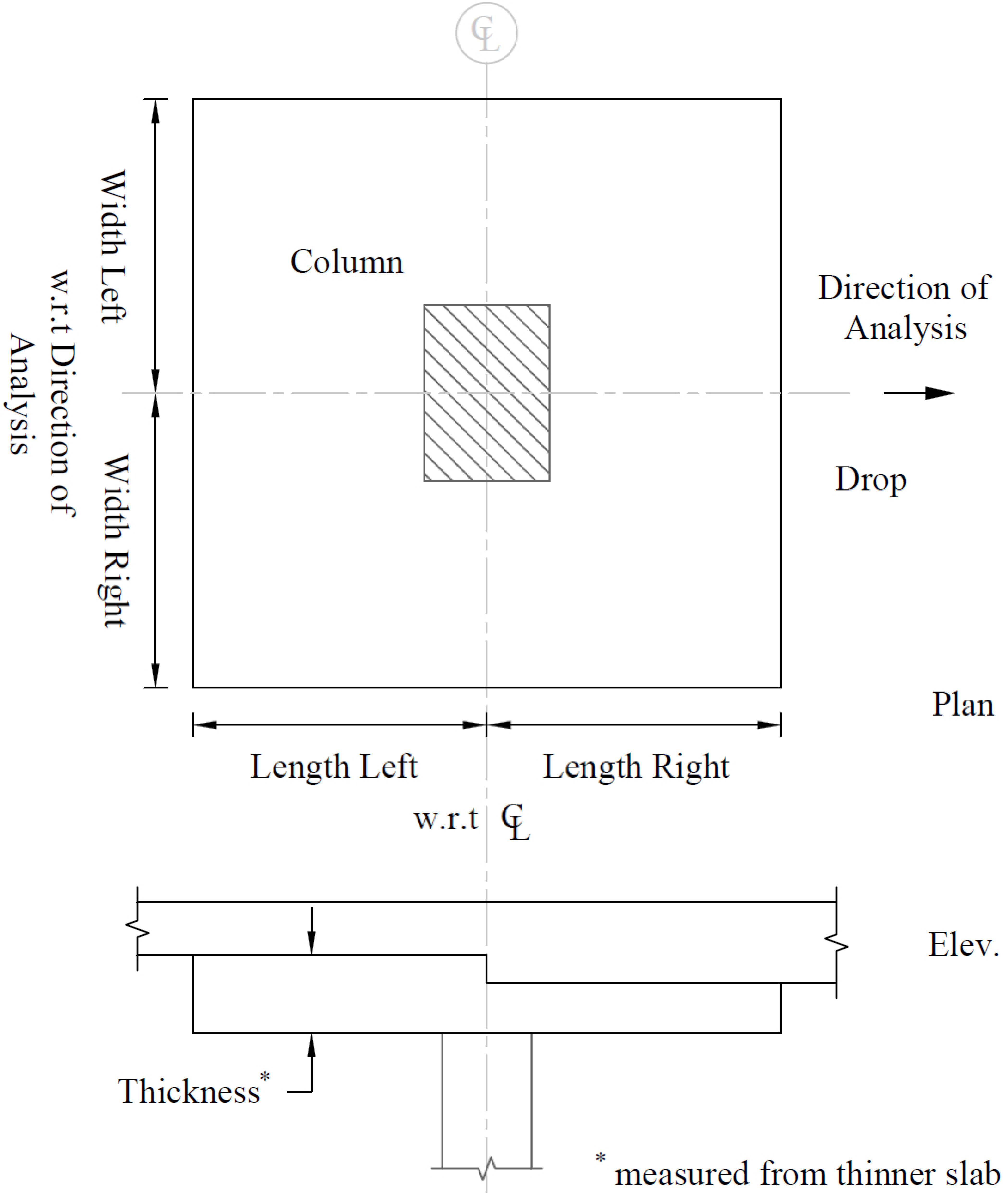
Figure 5.2 - Required Drop Panel Dimensions
You can enter the DEPTH and SIDE SLOPE data in the Left Panel. Then click on the desired support (or drag over multiple supports) to assign the column capital.
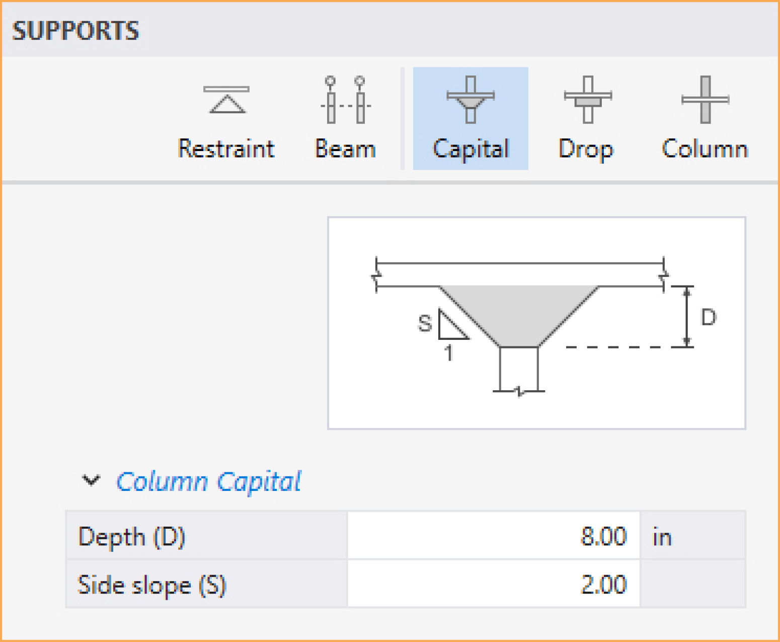
Enter the capital DEPTH which is the distance from the bottom of the soffit (slab, drop, or beam), to the bottom of the capital.
Enter the capital SIDE SLOPE which is the rate of depth to extension of the capital and it must be greater than 1 and smaller than 50.
For circular column capitals, in Design Options under Solve command, ensure the preferred option for punching shear perimeter is selected
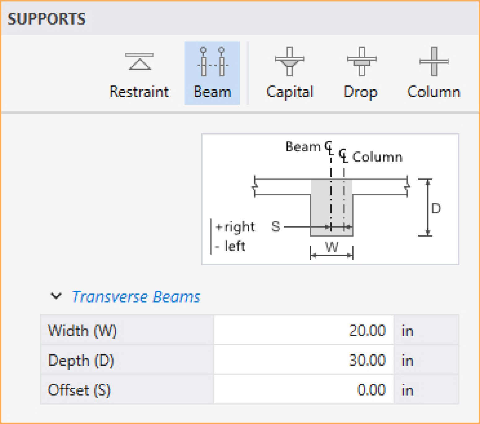
You can enter the WIDTH, DEPTH, and OFFSET data in the Left Panel. Then click on the desired support (or drag over multiple supports) to assign the beam.
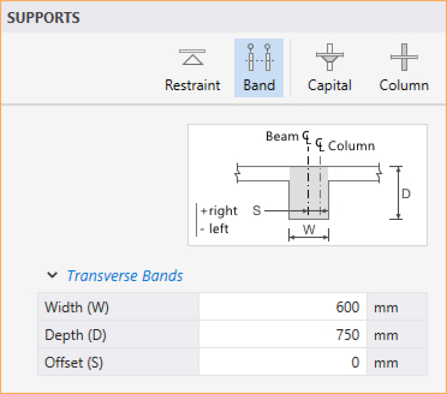
Transverse slab bands are only available for two-way floor systems when TRANSVERSE is selected for Slab Bands under Run Options in Project Left Panel (CSA A23.3-14/04 only). It is not required to input bands for every support. Supports where slab bands are not defined are modeled similar to regular two-way systems.
You can enter the WIDTH, DEPTH, and OFFSET data in the Left Panel. Then click on the desired support (or drag over multiple supports) to assign the slab band.
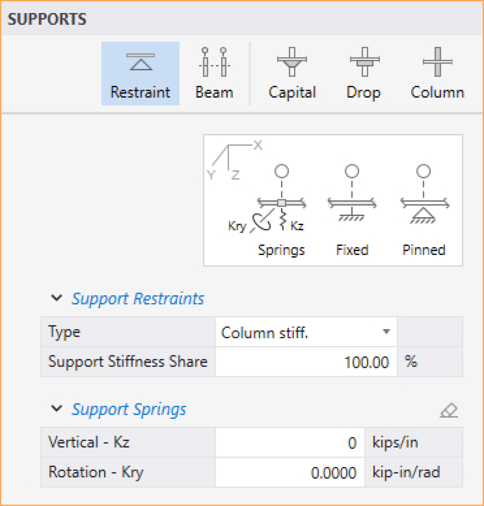
You can enter the SUPPORT RESTRAINTS, and SUPPORT SPRINGS data in the Left Panel. Then click on the desired support (or drag over multiple supports) to assign the restraint/spring.
This command is only available for one-way/beam floor systems when MOMENT REDISTRIBUTION option is checked in the Design & Modeling Options under the DEFINITIONS dialog box.
You can enter the redistribution factor you want to allow on the LEFT and RIGHT side of the support in the Left Panel. Then click on the desired support (or drag over multiple supports) to assign the redistribution limits.
5.2.4.3. Loads
spSlab computes the self-weight of the floor system. Other loads applied to the structure have to be specified by the user.
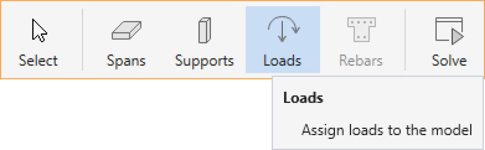
You can create Loads using the Loads command from the Ribbon.
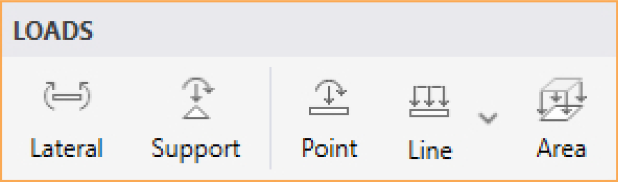
You can assign Area loads, Uniform and Variable Line loads, Point loads, Support loads and Displacements, and Lateral Load Effects loads by using one of the five options that are presented in the Loads Left Panel.
Area loads can only be assigned to Spans with a Slab and/or a Longitudinal Beam.
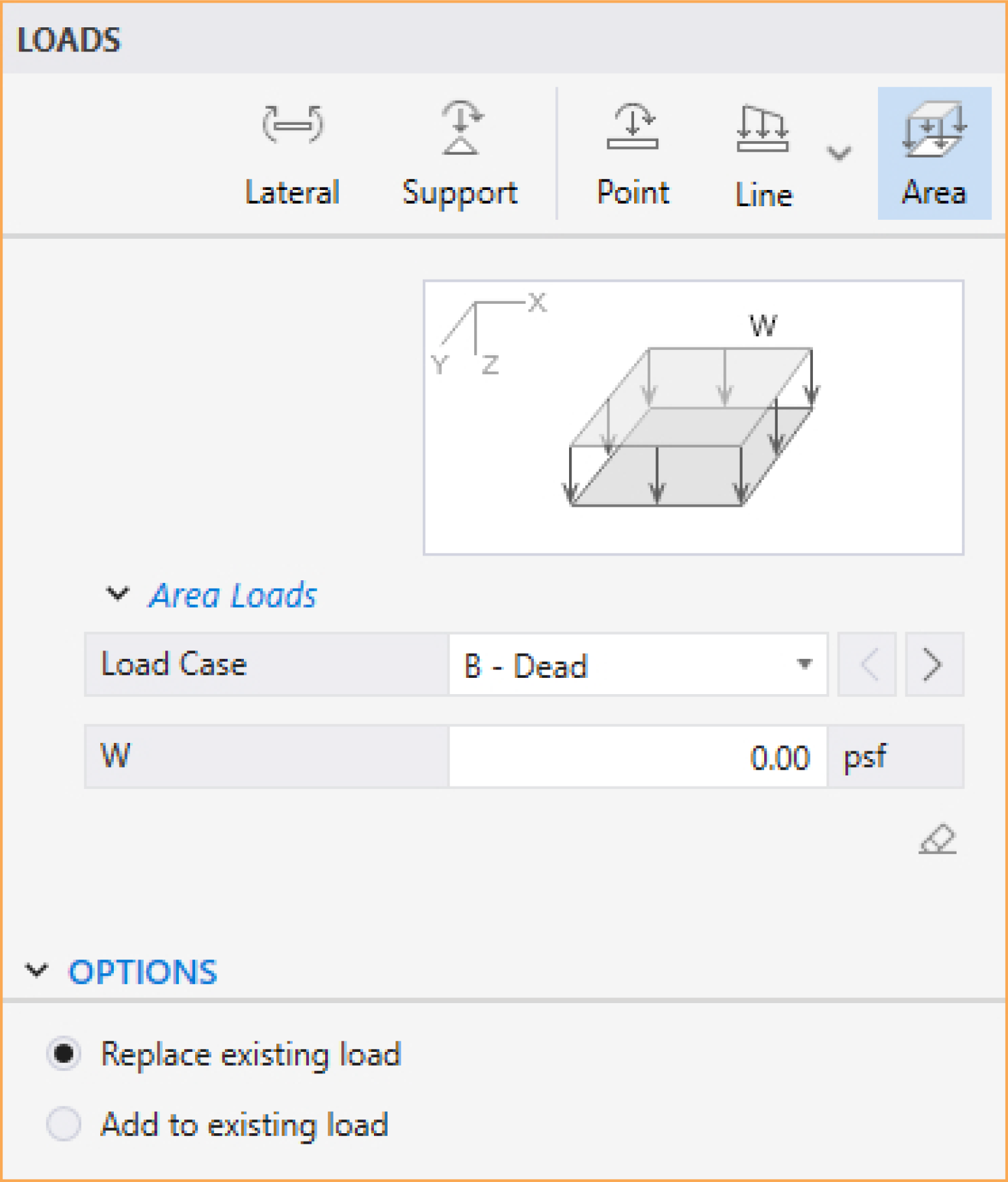
To assign an Area load, make sure that the Area command in the Left Panel is selected.
• Select the LOAD CASE you want the Area load to belong to. You can always define LOAD CASES in the DEFINITIONS dialog.
• In the W box, type in the required load value. Note that the thumbnail in the Left Panel shows the sign convention for the loads.
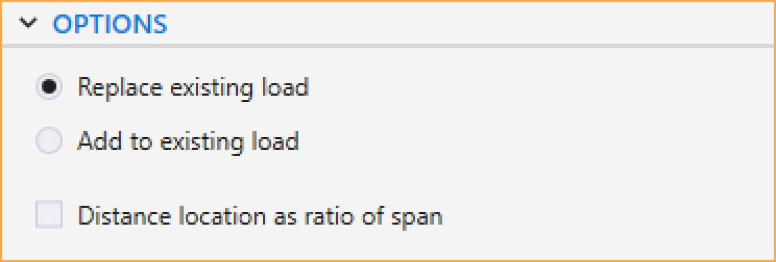
• From the OPTIONS select if you want to ADD TO EXISTING LOAD on the span or REPLACE EXISTING LOAD completely.
• Next, click on the span you want the load to be assigned to. You can also marquee select a group of spans to assign all of them the same area load.
Line loads can only be assigned to spans with a Slab and/or a Longitudinal Beam.
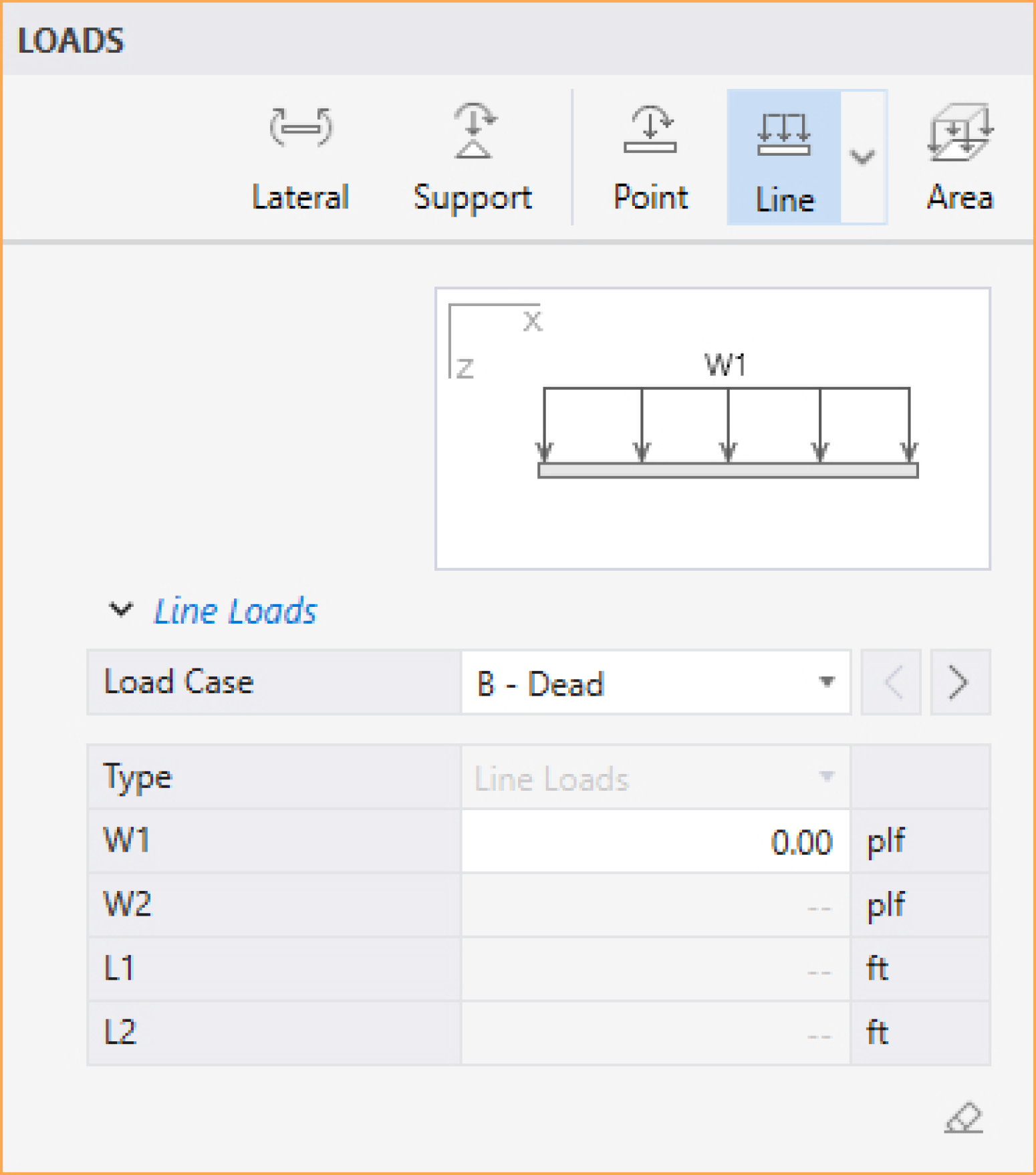
To assign a Line load, make sure that the Line command in the Left Panel is selected.
• Select the LOAD CASE you want the Line load to belong to. You can always define LOAD CASES in the DEFINITIONS dialog.
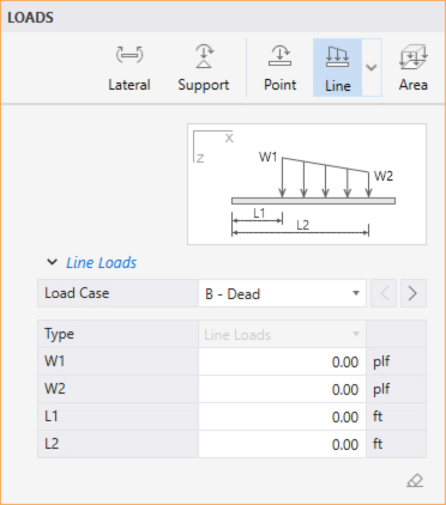
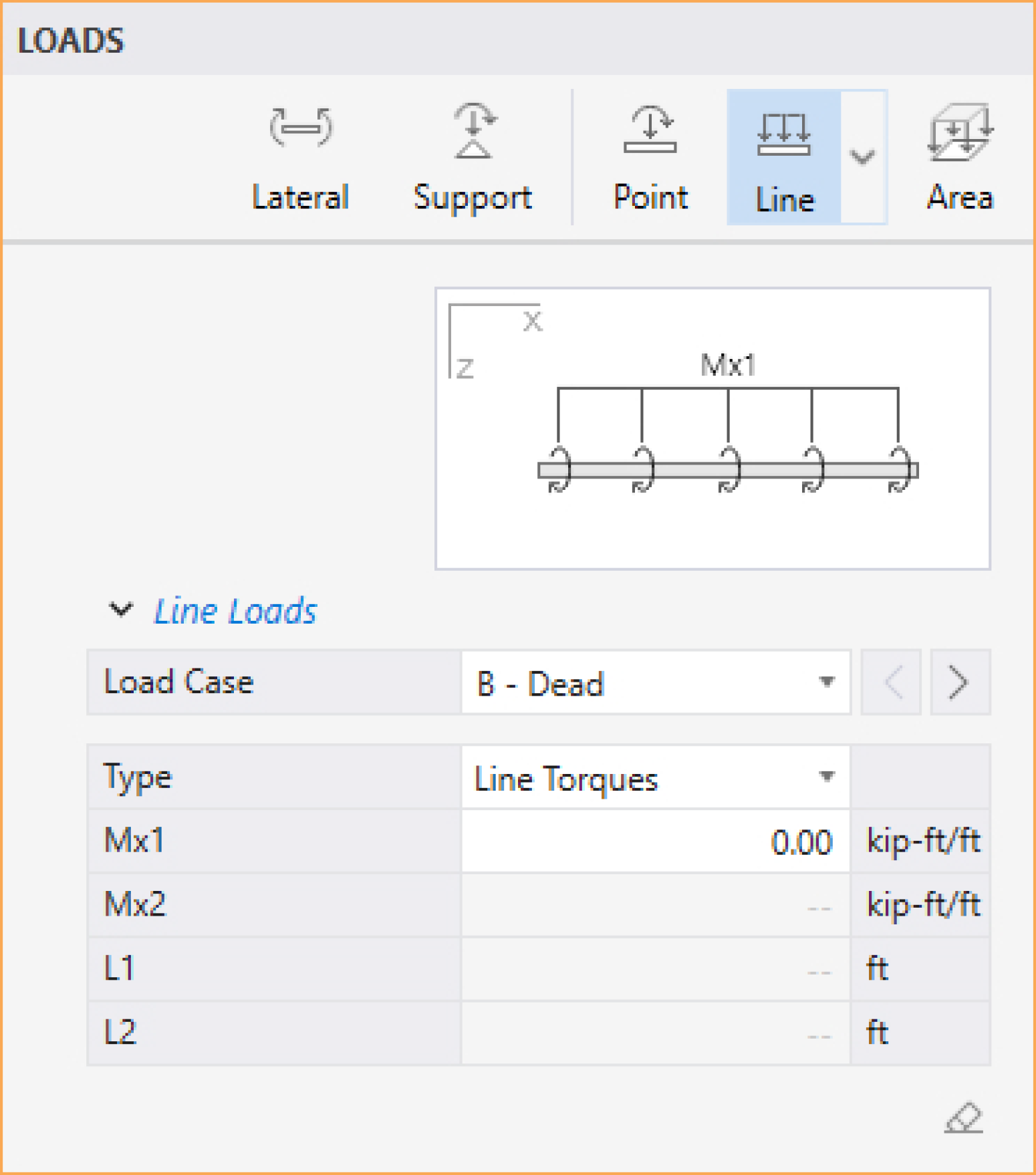
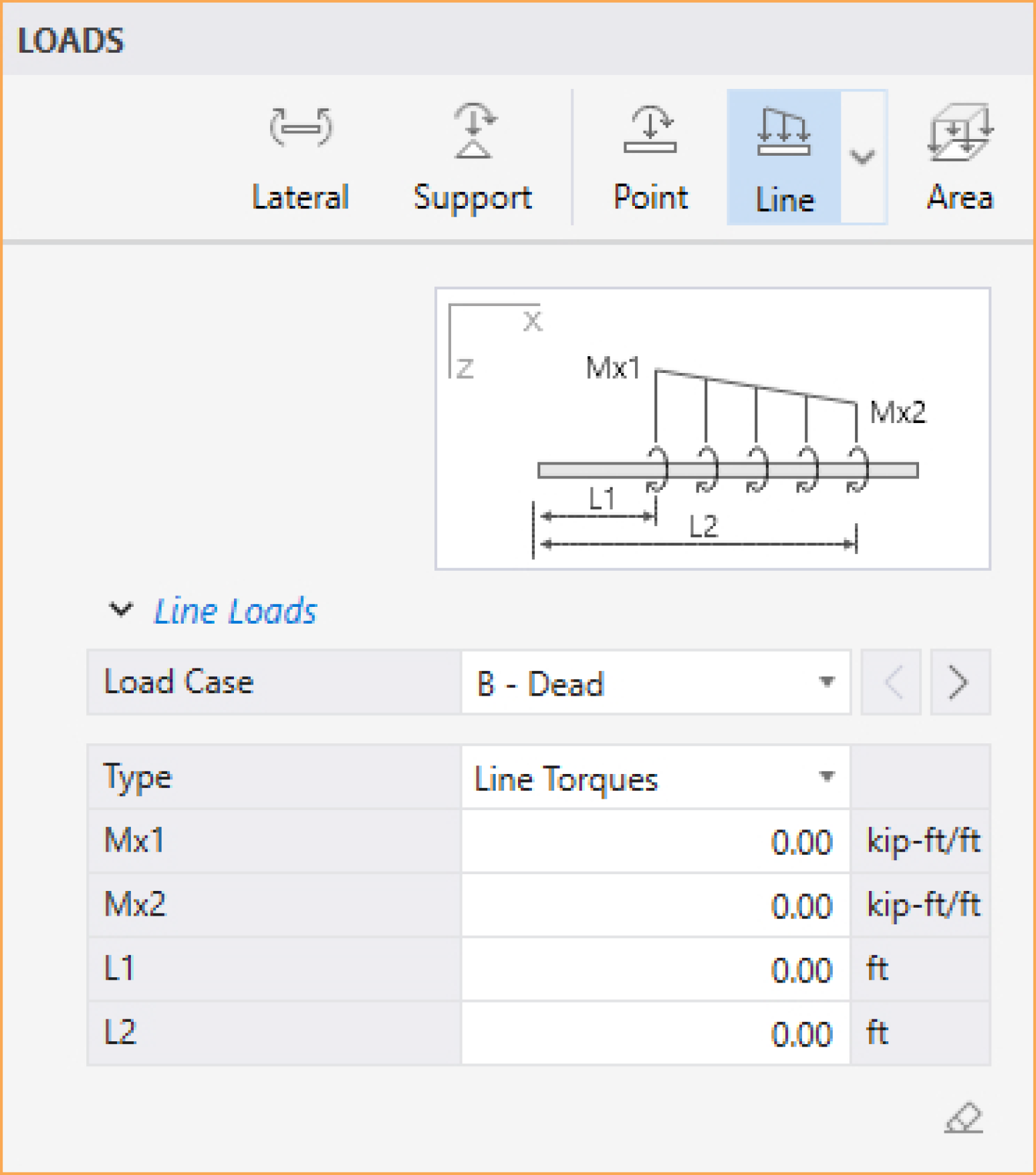
• Select the line load TYPE (UNIFORM LINE LOADS, UNIFORM LINE TORQUES, VARIABLE LINE LOADS, and VARIABLE LINE TORQUES). Note that UNIFORM LINE TORQUES and VARIABLE LINE TORQUES are only available for one-way floor systems when YES is selected for Consider Torsion under Run Options in Project Left Panel.
• In the boxes, type in the required location and load values. Note that the thumbnail in the Left Panel shows the sign convention for the loads.
• From the OPTIONS:
• Select if you want to ADD TO EXISTING LOAD on the span or REPLACE EXISTING LOAD completely.
• If you want to enter the required location as a ratio of the span length, check DISTANCE LOCATION AS RATIO OF SPAN checkbox.
• Next, click on the span you want the load to be assigned to. You can also marquee select a group of spans to assign all of them the same line loads.
Point loads can only be assigned to spans with a Slab and/or a Longitudinal Beam.
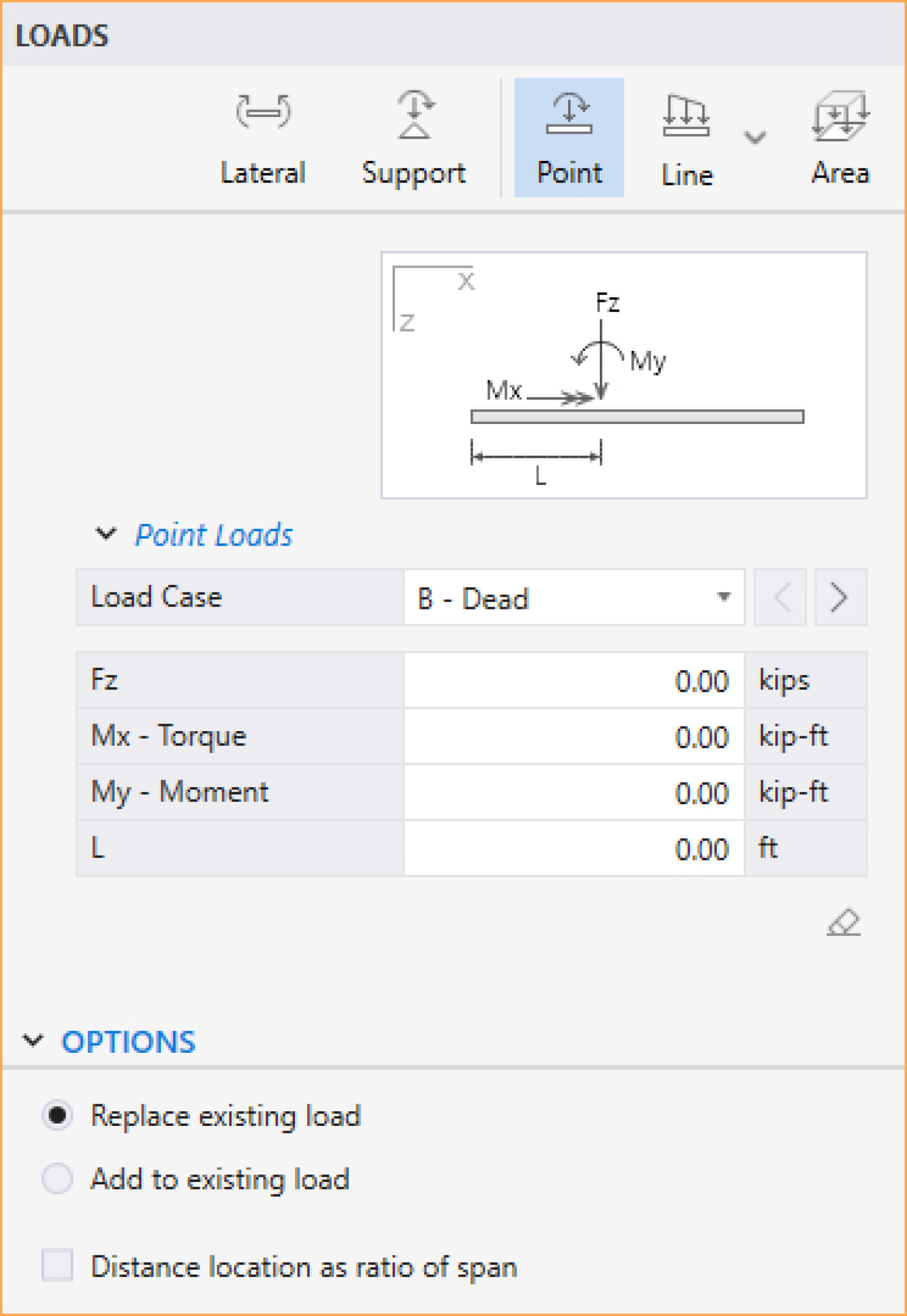
To assign a Point load, make sure that the Point command in the Left Panel is selected. The Left Panel should be displaying various Point loads options.
• Select the LOAD CASE you want the Point load to belong to. You can always define LOAD CASES in the DEFINITIONS dialog.
• In the boxes, type in the required load values and their locations. Note that the thumbnail in the Left Panel shows the sign convention for the loads, moments, and lengths.
• From the OPTIONS:
• Select if you want to ADD TO EXISTING LOAD on the span or REPLACE EXISTING LOAD completely.
• If you want to enter the required location as a ratio of the span length, check DISTANCE LOCATION AS RATIO OF SPAN checkbox.
• Next, click on the span you want the load to be assigned to. You can also marquee select a group of spans to assign all of them the same point loads.
Assigning Support Loads and Displacements
Support loads and displacements can only be assigned at support locations.
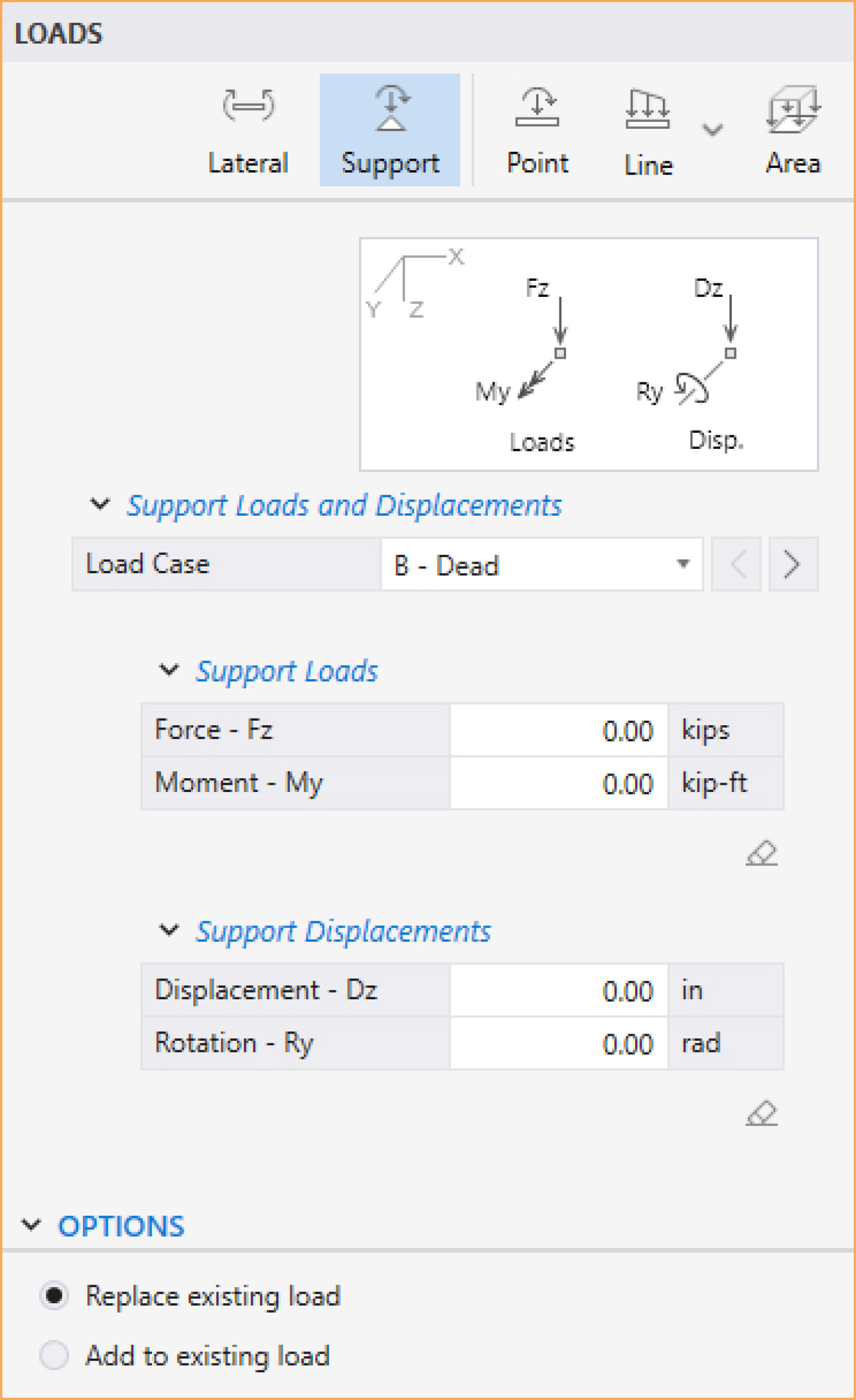
To assign a Support load and displacement, make sure that the Support command in the Left Panel is selected. The Left Panel should be displaying various Support loads and displacements options.
• Select the LOAD CASE you want the Support load and displacement to belong to. You can always define LOAD CASES in the DEFINITIONS dialog.
• In the SUPPORT LOADS boxes, type in the required FORCE and/or MOMENT values. Note that the thumbnail in the Left Panel shows the sign convention for the support loads.
• In the SUPPORT DISPLACEMENTS boxes, type in the required DISPLACEMENT and/or ROTATION values. Note that the thumbnail in the Left Panel shows the sign convention for the support displacements.
• From the OPTIONS select if you want to ADD TO EXISTING LOAD on the node or REPLACE EXISTING LOAD completely.
• Next, click on the support location you want the support load and displacement to be assigned to. You can also marquee select a group of supports to assign all of them the same support load and displacement.
Assigning Lateral Load Effects
Lateral Load Effects can only be assigned to Spans with a Slab and/or a Longitudinal Beam.
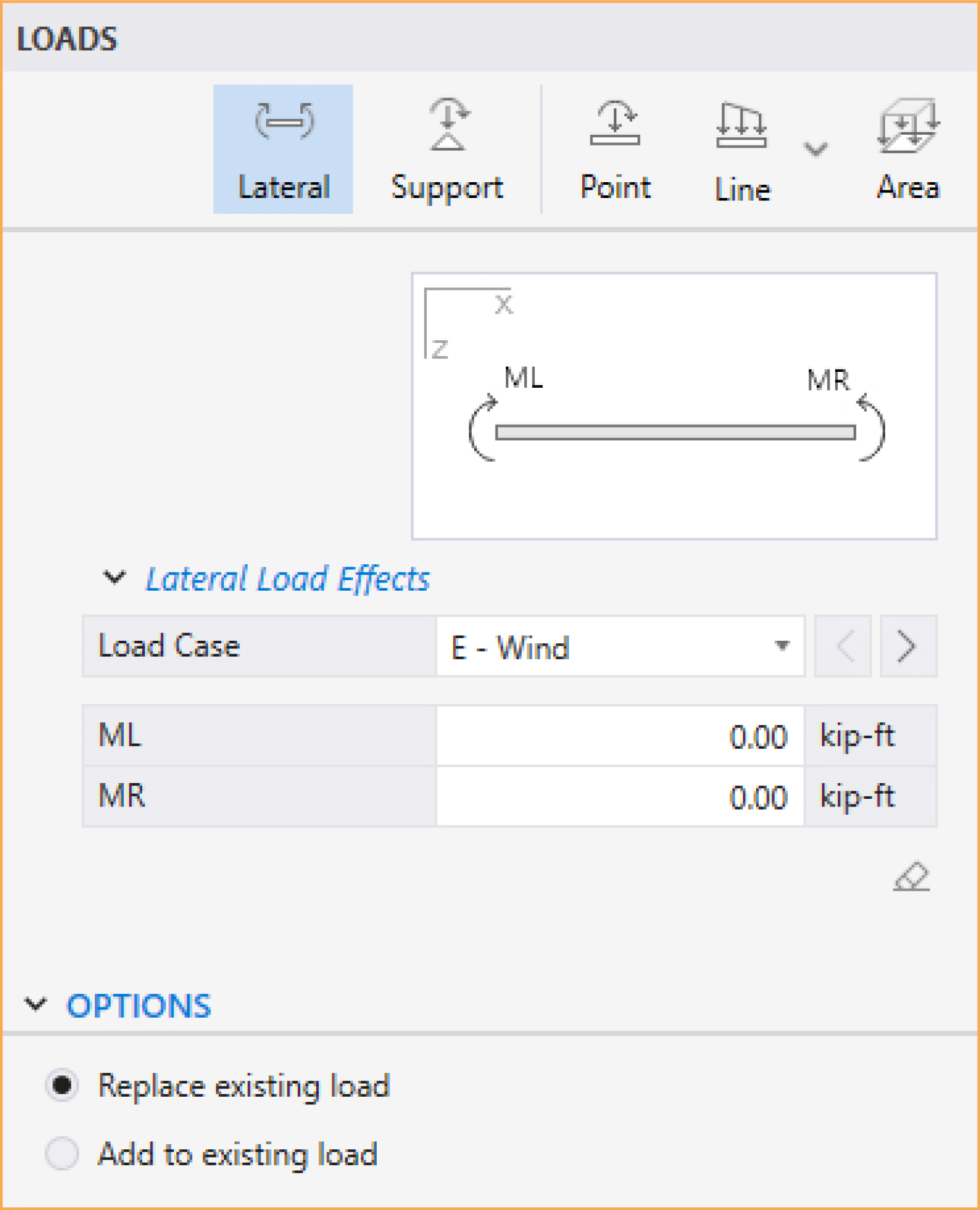
To assign a Lateral Load Effects, make sure that the Lateral command in the Left Panel is selected. The Left Panel should be displaying various Lateral loads options.
• Select the LOAD CASE you want the Lateral Load Effects to belong to. You can always define LOAD CASES in the DEFINITIONS dialog. Please note that at least one lateral load case is required to assign lateral load effects.
• In the boxes, type the moment values. Note that the thumbnail in the Left Panel show the sign convention for the lateral load effects.
• From the OPTIONS select if you want to ADD TO EXISTING LOAD on the span end or REPLACE EXISTING LOAD completely.
• Next, click on the span you want the lateral load effect to be assigned to. You can also marquee select a group of spans to assign all of them the same lateral load effect.
5.2.4.4. Rebars
Rebars command is only available if the RUN MODE of INVESTIGATION is selected in the Project Left Panel (This command is not available if RUN MODE of DESIGN is selected).
Note: When switching from DESIGN mode to INVESTIGATION mode, spSlab automatically assumes the results of the DESIGN mode as an input for INVESTIGATION mode.
You can create Rebars using the Rebars command from the Ribbon.
Column Strip Rebars for Two-Way Slab Systems
The column strip rebars can be defined by users if the RUN MODE of INVESTIGATION and TWO-WAY FLOOR SYSTEM are selected in the Project Left Panel.
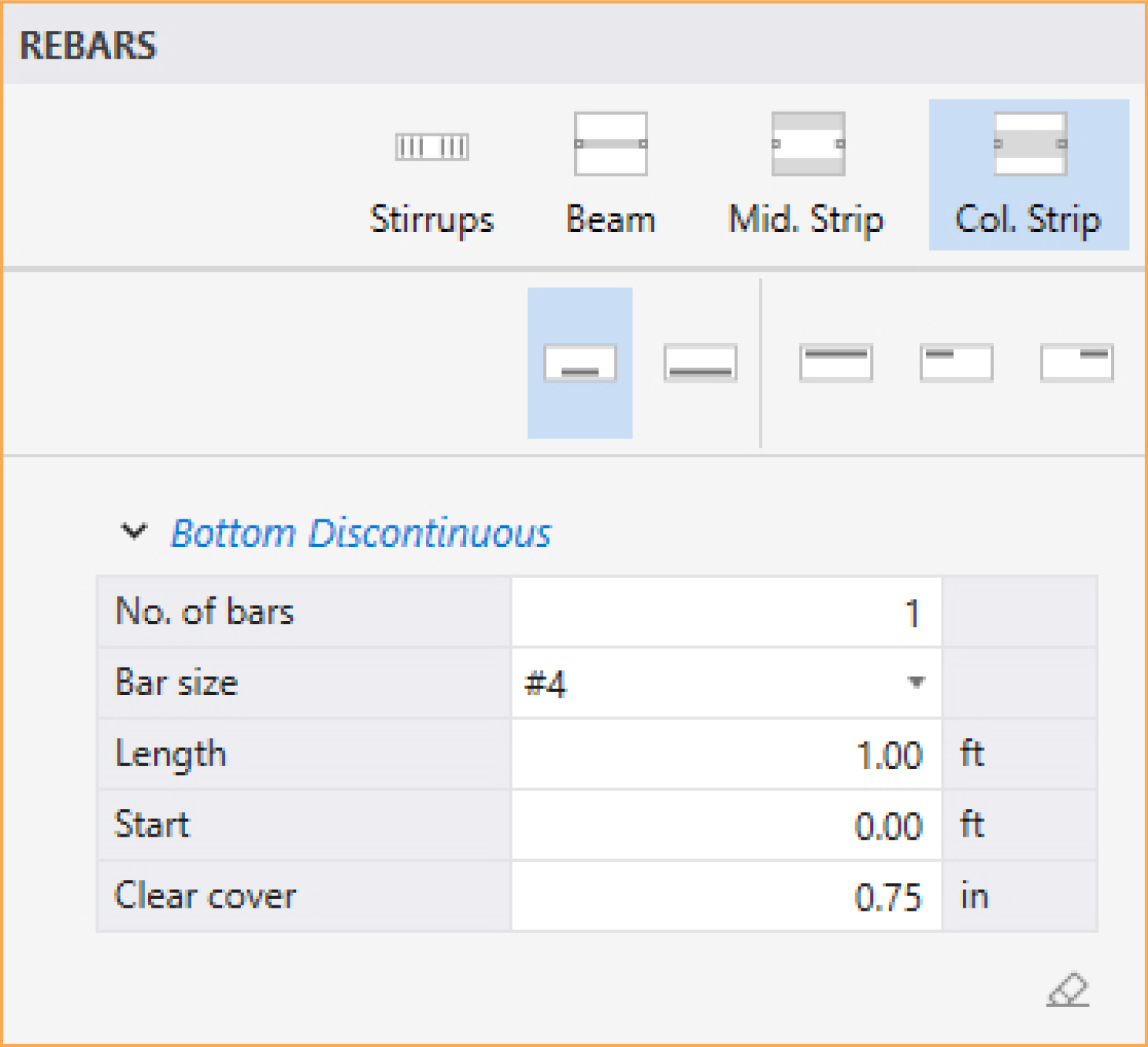
To define column strip rebars, make sure that the Column Strip command in the Left Panel is selected. The Left Panel should be displaying various Column Strip rebars types. Five types are available: Top Right, Top Left, Top Continuous, Bottom Continuous and Bottom Discontinuous.
• Select the rebar type for which Column Strip rebars will be defined.
• In the boxes, type in the NO. OF BARS, BAR SIZE, and CLEAR COVER (also bar LENGTH and START location, if discontinuous rebars types are selected).
• Next, click on the span (or spans) you want the Column Strip rebars to be assigned to. You can also marquee select a group of spans to assign all of them the same Column Strip rebars.
Middle Strip Rebars for Two-Way Slab Systems
The middle strip rebars can be defined by users if the RUN MODE of INVESTIGATION and TWO-WAY FLOOR SYSTEM are selected in the Project Left Panel.
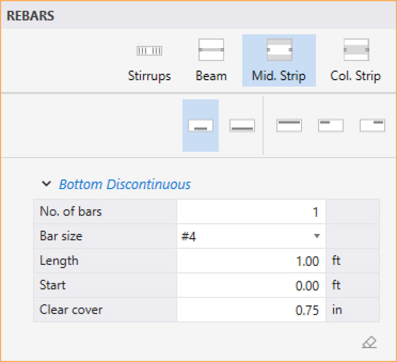
To define middle strip rebars, make sure that the Middle Strip command in the Left Panel is selected. The Left Panel should be displaying various Middle Strip rebars types. Five types are available: Top Right, Top Left, Top Continuous, Bottom Continuous and Bottom Discontinuous.
• Select the rebar type for which Middle Strip rebars will be defined.
• In the boxes, type in the NO. OF BARS, BAR SIZE, and CLEAR COVER (also bar LENGTH and START location, if discontinuous rebars types are selected).
• Next, click on the span (or spans) you want the Middle Strip rebars to be assigned to. You can also marquee select a group of spans to assign all of them the same Middle Strip rebars.
Beam Rebars for Two-Way Slab Systems
The beam rebars can be defined by users if the RUN MODE of INVESTIGATION and TWO-WAY FLOOR SYSTEM are selected in the Project Left Panel.
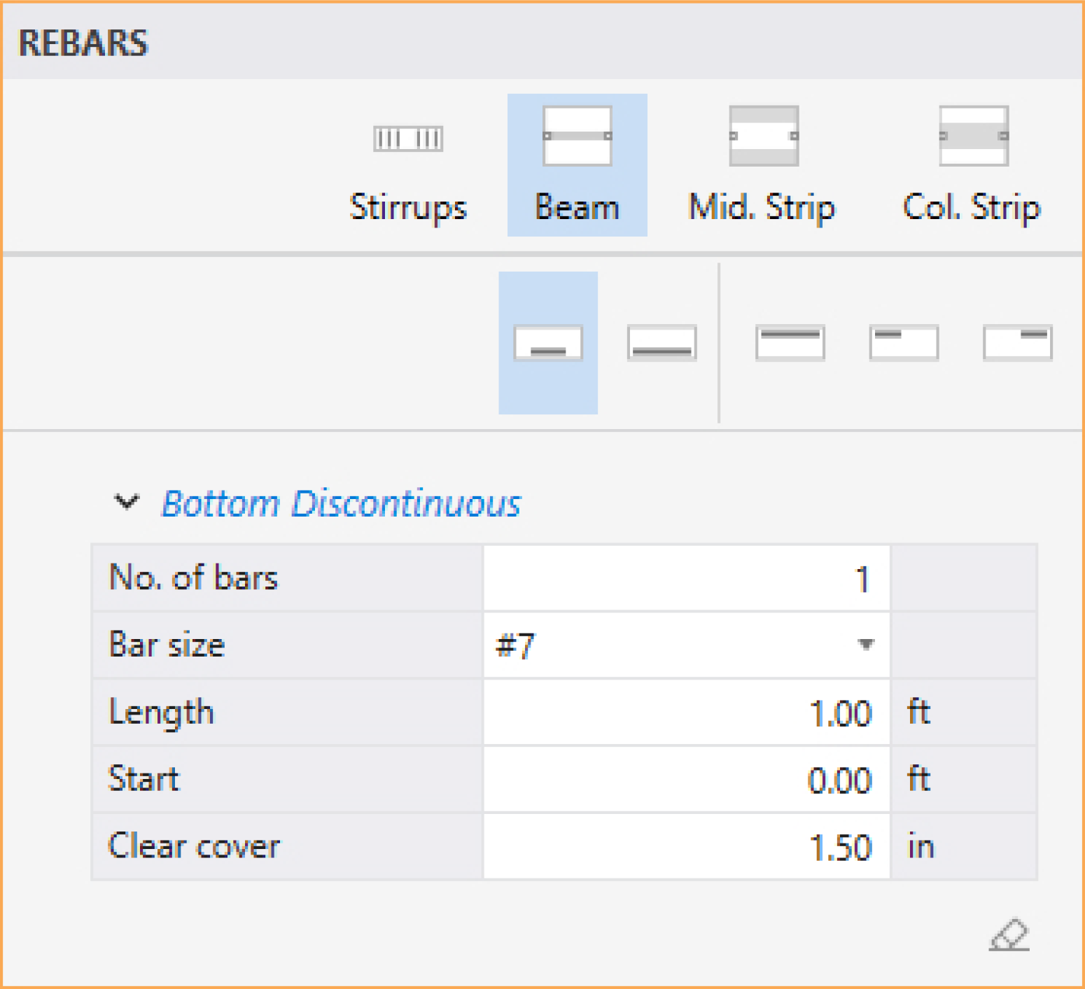
To define beam rebars, make sure that the Beam command in the Left Panel is selected. The Left Panel should be displaying various Beam rebars types. Five types are available: Top Right, Top Left, Top Continuous, Bottom Continuous and Bottom Discontinuous.
• Select the rebar type for which Beam rebars will be defined.
• In the boxes, type in the NO. OF BARS, BAR SIZE, and CLEAR COVER (also bar LENGTH and START location, if discontinuous rebars types are selected).
• Next, click on the span (or spans) you want the Beam rebars to be assigned to. You can also marquee select a group of spans to assign all of them the same Beam rebars.
Beam Stirrups for Two-Way Slab Systems
The beam stirrups can be defined by users if the RUN MODE of INVESTIGATION and TWO-WAY FLOOR SYSTEM are selected in the Project Left Panel.
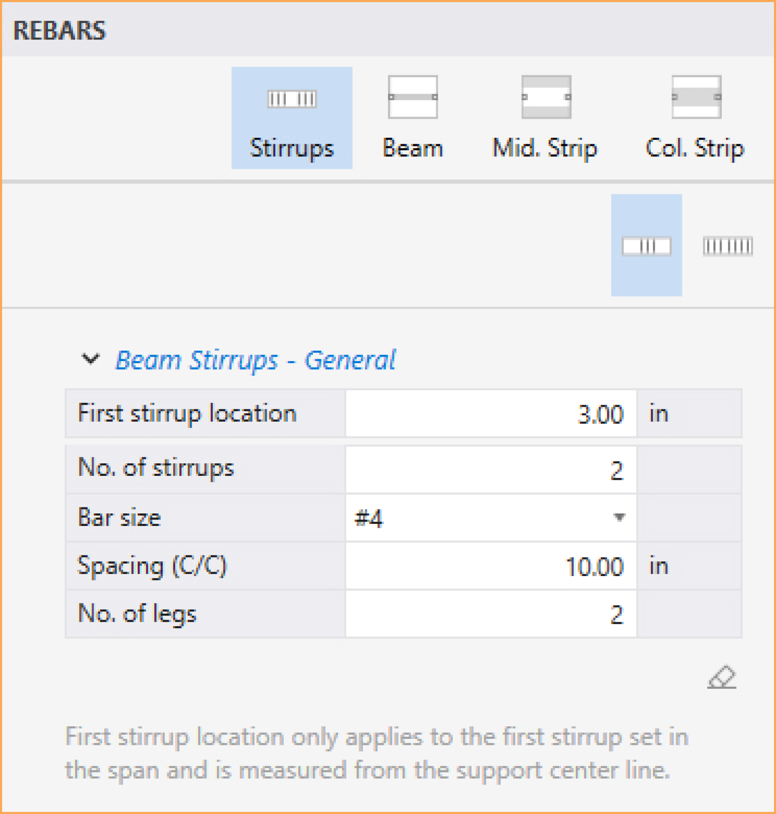
To define beam stirrups, make sure that the Stirrups command in the Left Panel is selected. The Left Panel should be displaying two Stirrups configurations: Stirrups Entire Span and Stirrups General.
• Select the stirrups configuration for which Stirrups will be defined.
• In the boxes, type in the NO. OF STIRRUPS, BAR SIZE, SPACING and NO. OF LEGS (also FIRST STIRRUP LOCATION when applicable).
• Next, click on the span (or spans) you want the Stirrups to be assigned to. You can also marquee select a group of spans to assign all of them the same Stirrups.
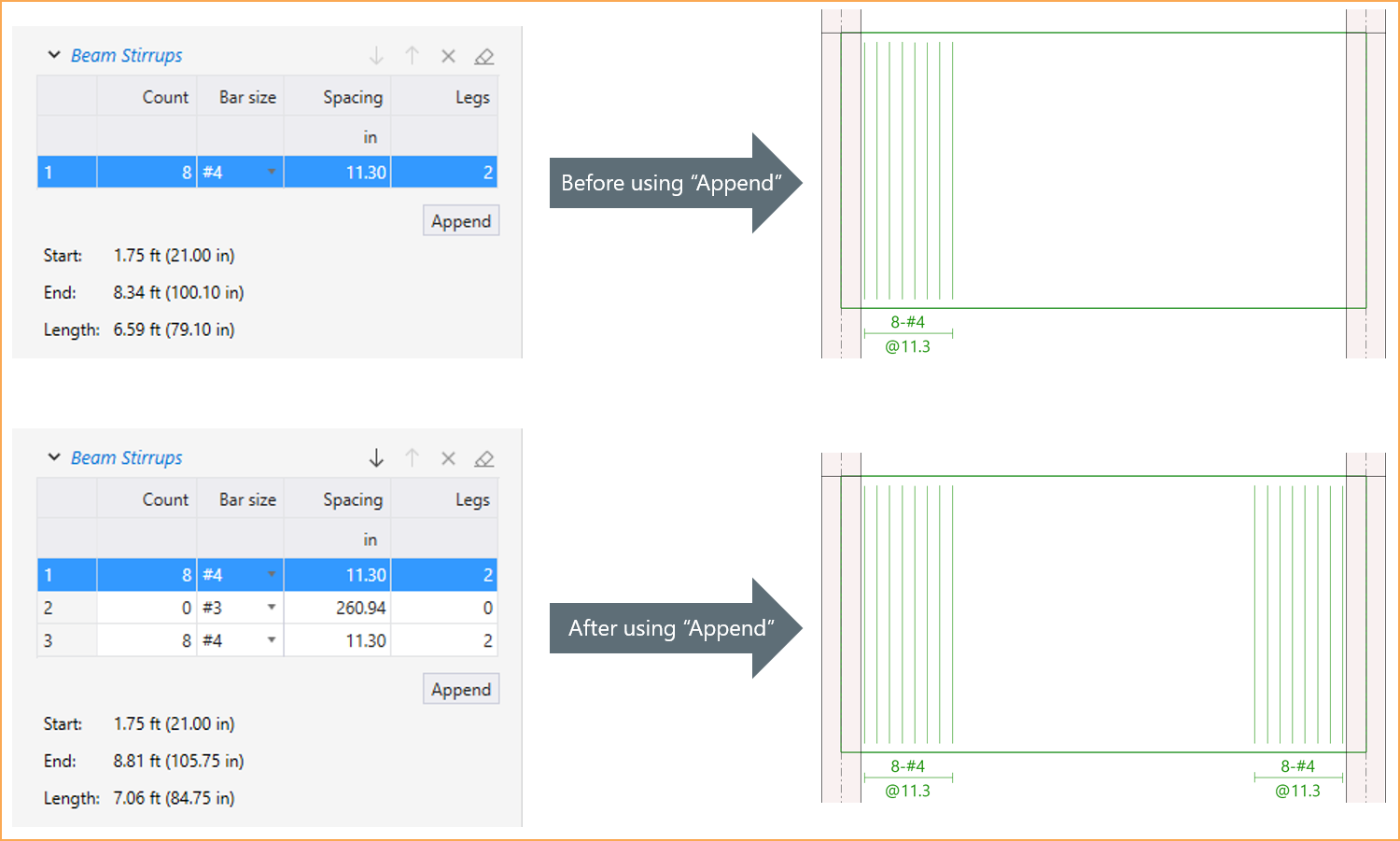
• In order to mirror stirrup set or sets at the end of the span, use APPEND button.
Flexural Rebars for Beams and One-Way Slab Systems
The flexure rebars can be defined by users if the RUN MODE of INVESTIGATION and ONE-WAY/BEAM FLOOR SYSTEM are selected in the Project Left Panel.
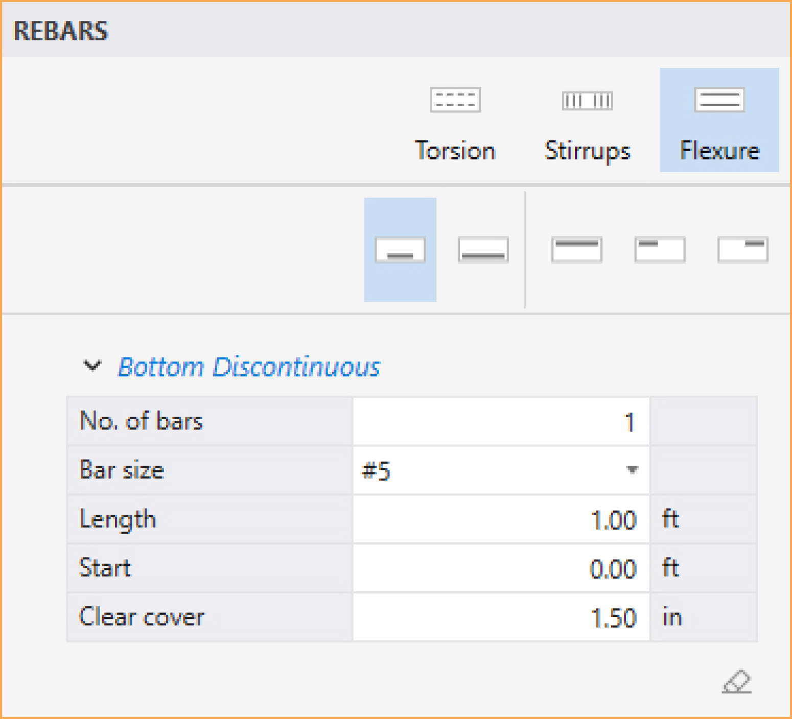
To define flexure rebars, make sure that the Flexure command in the Left Panel is selected. The Left Panel should be displaying various Flexure rebars types. Five types are available: Top Right, Top Left, Top Continuous, Bottom Continuous and Bottom Discontinuous.
• Select the rebar type for which Flexure rebars will be defined.
• In the boxes, type in the NO. OF BARS, BAR SIZE, and CLEAR COVER (also bar LENGTH and START location, if discontinuous rebars types are selected).
• Next, click on the span (or spans) you want the Flexure rebars to be assigned to. You can also marquee select a group of spans to assign all of them the same Flexure rebars.
Stirrups for Beams and One-Way Slab Systems
The stirrups can be defined by users if the RUN MODE of INVESTIGATION and ONE-WAY/BEAM FLOOR SYSTEM are selected in the Project Left Panel.
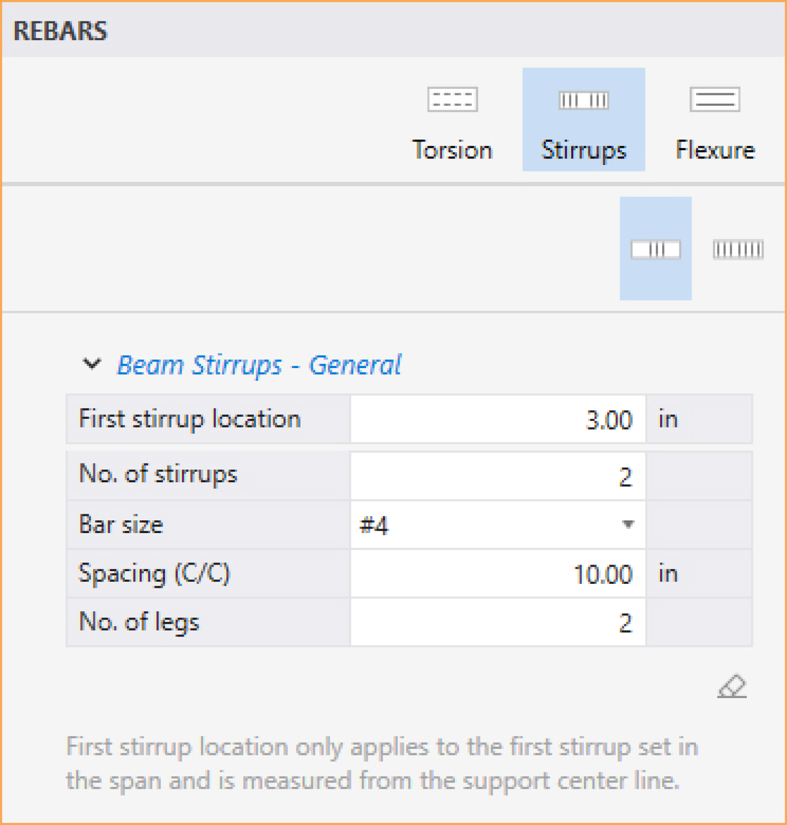
To define stirrups, make sure that the Stirrups command in the Left Panel is selected. The Left Panel should be displaying two Stirrups configurations: Stirrups Entire Span and Stirrups General.
• Select the stirrups configuration for which Stirrups will be defined.
• In the boxes, type in the NO. OF STIRRUPS, BAR SIZE, SPACING and NO. OF LEGS (also FIRST STIRRUP LOCATION when applicable).
• Next, click on the span (or spans) you want the Stirrups to be assigned to. You can also marquee select a group of spans to assign all of them the same Stirrups.
• In order to mirror stirrup set or sets at the end of the span, use APPEND button.
Torsional Longitudinal Rebars for Beams
The torsional longitudinal rebars can be defined by users if the RUN MODE of INVESTIGATION and ONE-WAY/BEAM FLOOR SYSTEM are selected in the Project Left Panel.
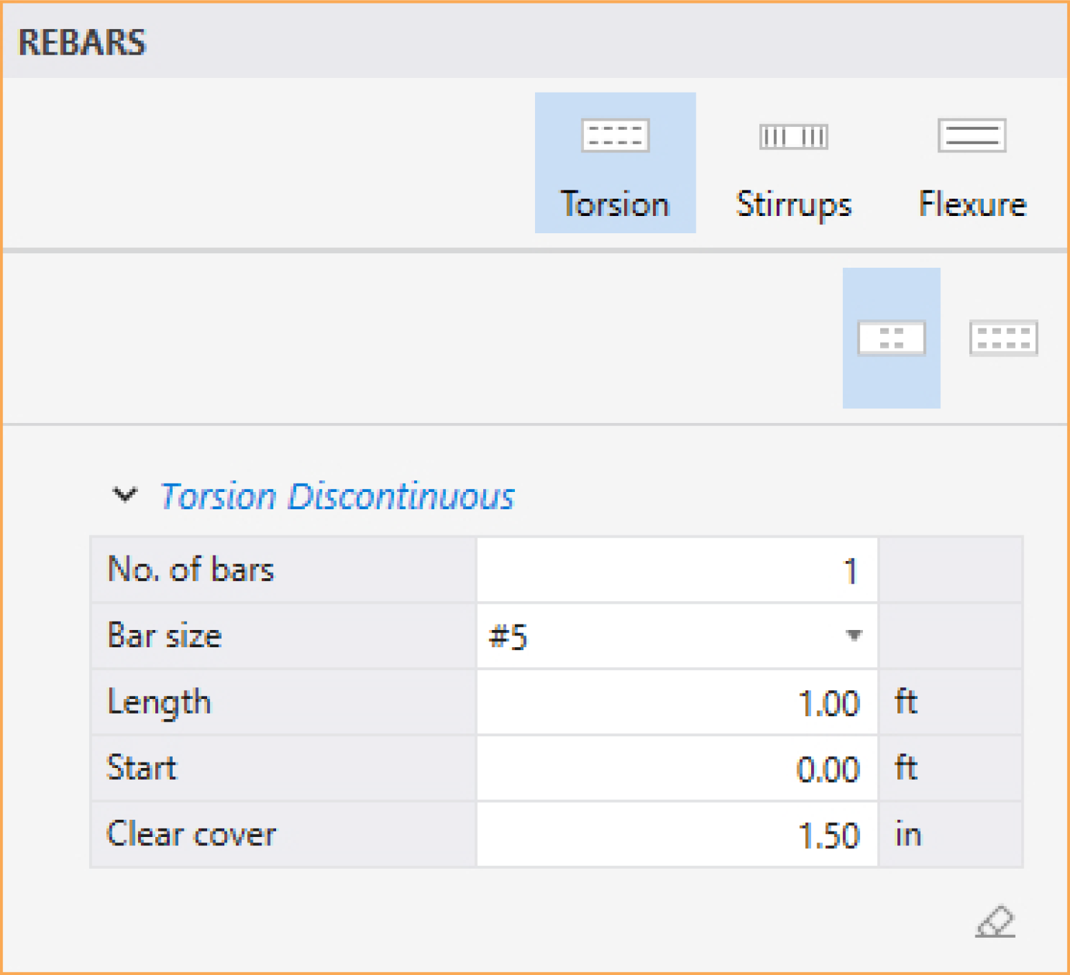
To define torsional longitudinal rebars, make sure that the Torsion command in the Left Panel is selected. The Left Panel should be displaying various Torsion rebars types. Two types are available: Torsion Continuous and Torsion Discontinuous.
• Select the rebar type for which Torsion rebars will be defined.
• In the boxes, type in the NO. OF BARS, BAR SIZE, and CLEAR COVER (also bar LENGTH and START location, if discontinuous rebars type is selected).
• Next, click on the span (or spans) you want the Torsion rebars to be assigned to. You can also marquee select a group of spans to assign all of them the same Torsion rebars.
The model can be edited by using the Left Panel, Left Panel Toolbar or by using right-click at Viewport. To edit a model element, its corresponding placeholder (Span or Support) must be selected.
The Elements that can be edited are: Slabs, Longitudinal Beams/Bands, Ribs, Columns, Drop Panels, Column Capitals and Transverse Beams/Bands.
The corresponding Spans Left Panel provides various tools and options for effectively working with Span Elements. You must have the Select command button toggled on to edit the Span Elements.
Editing Span Elements
To edit span elements:
• Click on the span (or spans) you want to edit to display its properties in the Left Panel.
• Then in the Elements tab in the Span Left Panel, simply change the desired parameter.
• Additionally, you can add new elements or remove existing elements to the selected span (or spans) by clicking on  or
or  next to the desired element, respectively.
Editing Span Loads
To edit span loads:
• Click on the span (or spans) you want to edit to display its properties in the Left Panel.
• Click on the Loads tab in the Span Left Panel, then simply change the load value as desired.
• Additionally, you can add new loads or remove existing loads to the selected span by clicking on or next to the desired load, respectively.
Editing Strip Moment Distribution Factors
To edit strip Moment Distribution Factors:
• Enable check box USER STRIP DISTRIBUTION FACTORS under Design & Modeling Options under the Define command.
• You must have the Select command button toggled on to edit the Spans.
• Click on the span (or spans) you want to edit to display its properties in the Left Panel.
• Click on next to the strips Moment Distribution table.
• Then in Moment Distribution table in the Span Left Panel, simply change the desired factors.
The corresponding Support Left Panel provides various options for effectively working with Support. You must have the Select command button toggled on to edit the Support.
Editing Supports Elements
To edit supports elements:
• Click on the support (or supports) you want to edit to display its properties in the Left Panel.
• Then in the Elements tab in the Span Left Panel, simply change the desired parameter.
• Additionally, you can add new elements or remove existing elements to the selected support (or supports) by clicking on or next to the desired element, respectively.
Editing Support Loads & Restraints
To edit support loads & restraints:
• Click on the support (or supports) you want to edit to display its properties in the Left Panel.
• Click on the Loads & Restraints tab in the Span Left Panel, then simply change the load or restraint value as desired.
• Additionally, you can add new loads (or restraints) or remove existing loads (or restraints) to the selected support by clicking on or next to the desired load (or restraint), respectively.
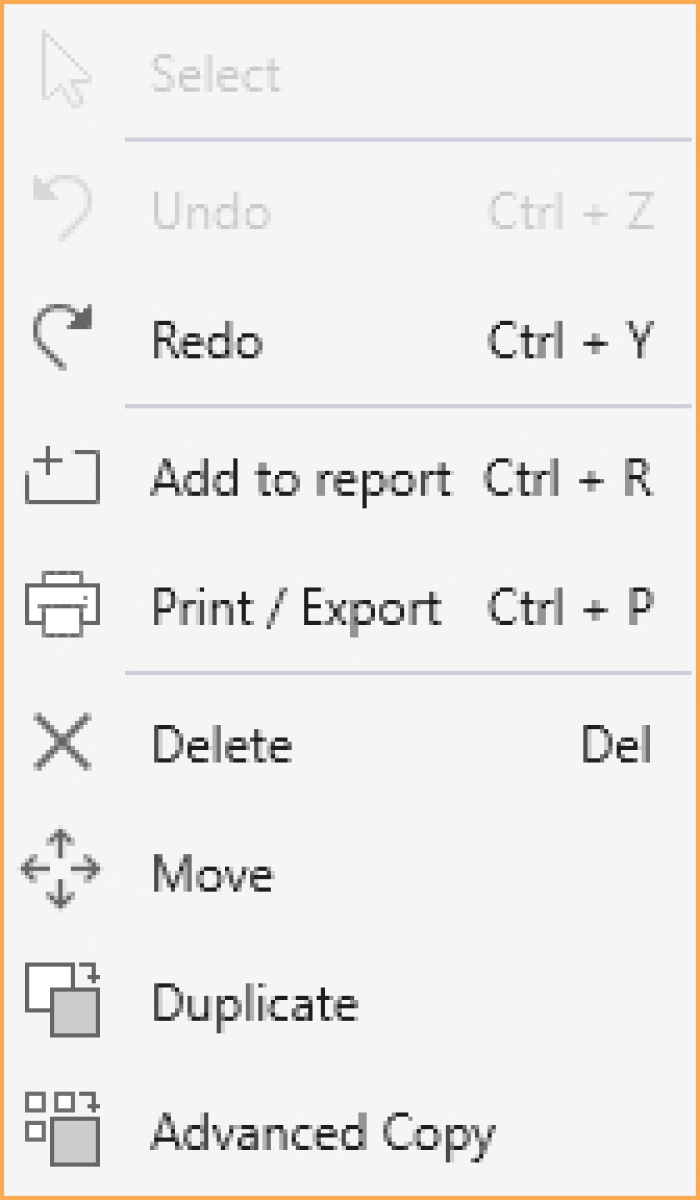
5.2.5.2. Using the Left Panel Toolbar
You must have the Select command button toggled on in order to use the tools available in the Left Panel Toolbar. You can use the tools in the Left Panel Toolbar to edit various model items.
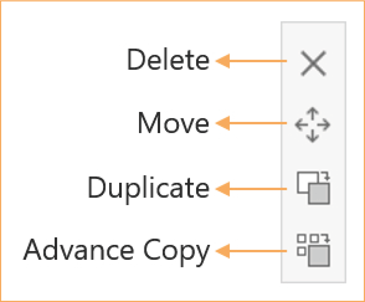
The Delete command is active only when one or more supports are selected.
• Select the support or supports you want to remove from the model and click Delete to remove.
The Move command is active only when one support is selected.
• Select the support you want to move and click the Move command.
• Specify the destination support to complete moving.
The Duplicate command is active only when one span or support is selected.
• Select the span or support you want to duplicate of and click the Duplicate command.
• Specify the destination span or support to complete duplication.
The Advanced Copy command is active only when one span or support is selected.
• Select the span or support you want to copy of and click the Advanced Copy command.
• Select the properties, load types and load cases you want to copy and click the Ok button.
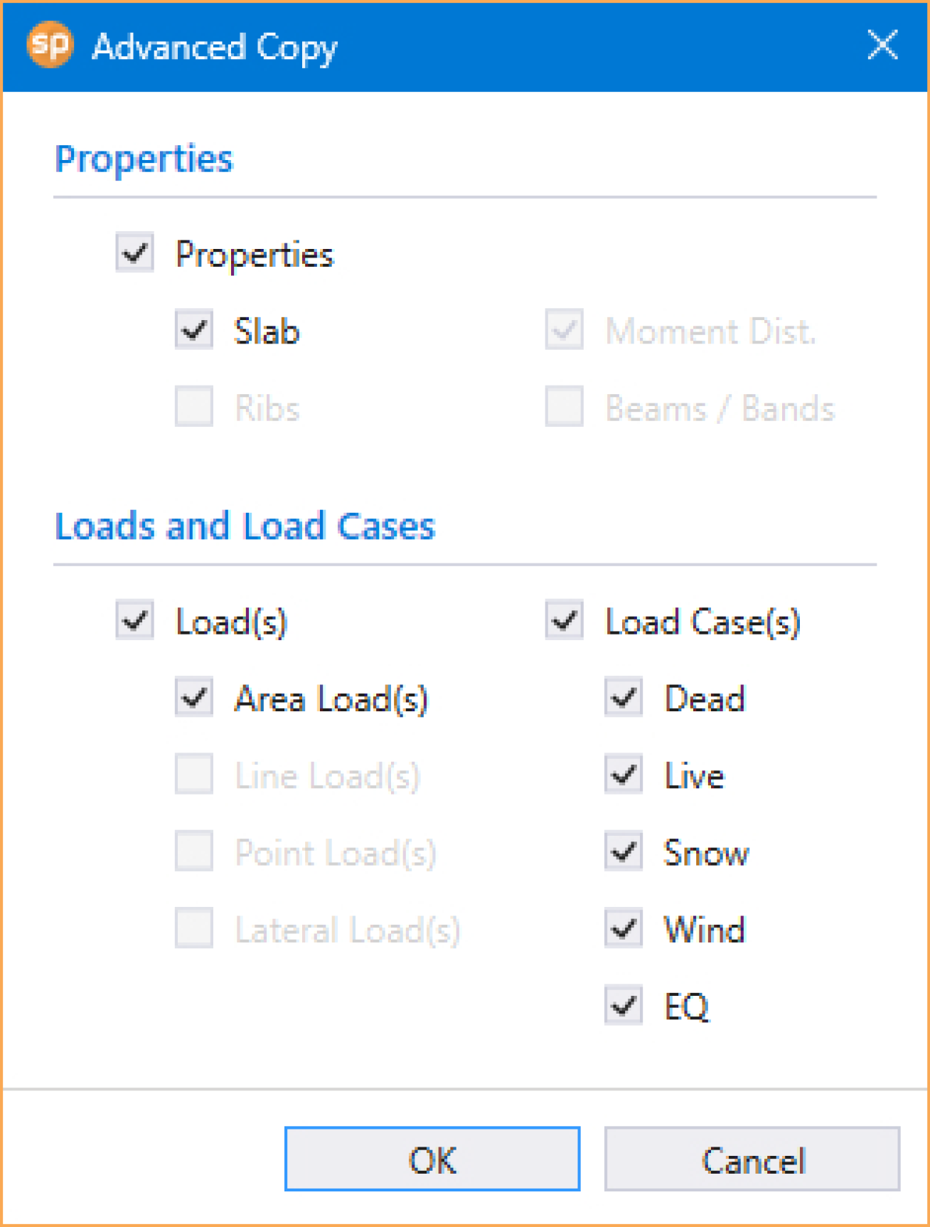
• Specify the destination span or support to complete advanced copy.
5.2.5.3. Using the Right Click Menu at Viewport
All the tools in the Left Panel Toolbar are also available in the Right Click Menu at Viewport when the Select command button is toggled on.