2.2. Codes and Standards Provisions
2.2.1.1. Geometry Considerations
Minimum Thickness – One-Way Construction
The program checks beam or one-way slab thickness based on minimum requirement for ACI-3181 code as specified in Table 9.5(a) or for CSA code2 according to Table 9.2. For light weight concrete with density.
90 lb/ft3 ≤ wc ≤ 115 lb/ft3 [1440 kg/m3 ≤ wc ≤ 1840 kg/m3] for ACI 318-14, ACI 318-11, and ACI 318-08
90 lb/ft3 ≤ wc ≤ 120 lb/ft3 [1440 kg/m3 ≤ wc ≤ 1920 kg/m3] for ACI 318-05
90 lb/ft3 ≤ wc ≤ 120 lb/ft3 [1500 kg/m3 ≤ wc ≤ 2000 kg/m3] for ACI 318-02, and ACI 318-99,
the minimum slab thickness is additionally increased by adjustment factor (1.65 – 0.005wc), but not less than 1.09. For CSA standards, the adjustment is calculated as (1.65 – 0.0003wc), but not less than 1.0, for structural low density (wc ≤ 1850 kg/m3) and structural semi-low density (1850 kg/m3 ≤ wc ≤ 2150 kg/m3) concrete3.
Minimum Slab Thickness – Two-Way Construction
The program checks slab thickness against minimum slab thickness defined by design standards for two-way systems with long to short span ratio not greater than 2.04. Slabs with thickness below the minimum value will be flagged by the program, however, they are allowed provided that calculated deflections do not exceed maximum permissible computed deflections5.
For two-way system with a long to short span ratio greater than 2.0, the program will calculate minimum thickness requirements based on the provisions of one-way construction including any cantilevered spans.
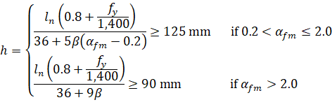
Minimum thickness of slabs with beams spanning between supports on all sides is calculated for ACI 318 codes in US customary units from6:
Eq. 2-1 |
in metric unit system for ACI 318-14, ACI 318-11, ACI 318-08, and ACI 318-05 from7:
| Eq. 2-2 |
and in metric unit system for ACI 318-02, and ACI 318-99 from8:
| Eq. 2-3 |
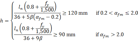
where: | ||
• ln | = | longer clear span measured face-to-face of beams, |
• β | = | ratio of the clear spans in long to short direction, |
• fy | = | yield stress of reinforcing steel, |
• αfm | = | average value of αf, the ratio of flexural stiffness of a beam section to the flexural stiffness of a width of slab bounded laterally by centerlines of adjacent panels on either side of the beam, for all beams supporting the edges of a slab panel. |
The program assumes that beams are present on all sides of a panel if the span under consideration includes a longitudinal beam and there are transverse beams defined at both ends of the span. If this assumption is satisfied but in reality beams are not present on all sides (e.g. design strip next to the one under consideration has no longitudinal beam) then the user is advised to check deflections even if slab thickness is larger than the minimum slab thickness reported by the program.
For the design of ACI slabs without beams (αfm ≤ 0.2) spanning between interior supports the minimum thickness shall conform to ACI 318 Table 9.5(c) and will not be less than 5.0 in. [125 mm for ACI 318M-11/08/05 or 120 mm for ACI 318M-02/99] for flat plates (slabs without drop panel) and not less than 4.0 in. [100 mm] for two-way flat slab systems (slab with drop panels)9. For flat slabs that contain valid drop panels (see Figure 2.4), Table 9.5(c) reduces the minimum thickness by approximately 10%. For values of fy between the ones given in the table, minimum thickness is determined by linear interpolation.
For design strips that have neither beams between all supports nor beams between interior supports (e.g. exterior strips with beams on the outside edges only), the program reports maximum value of minimum slab thickness resulting from both Table 9.5(c) and Equations. However, since this case is not explicitly covered by the ACI code, the user is advised to check deflections even if slab thickness is larger than the minimum slab thickness reported by the program.
For CSA A23.3 standard10, the minimum thickness of slab with beams spanning between all supports is:
| Eq. 2-4 |
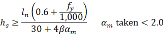
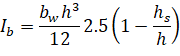
with the value of αm evaluated for CSA A23.3-04 using the following beam moment of inertia:
| Eq. 2-5 |
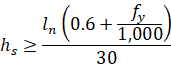
For flat plates and slabs with column capitals11, the minimum slab thickness is:
| Eq. 2-6 |
For slabs with drop panels12, the minimum slab thickness satisfies the conditions:
| Eq. 2-7 |
| Eq. 2-8 |
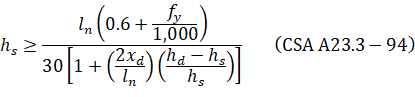
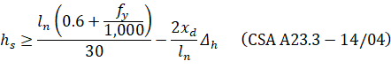
where (hd – hs) shall not be greater than hs and | ||
• xd | = | dimension from face of column to edge of drop panel, but not more than ln / 4, |
• 2xd/ln | = | the smaller of the values determined in the two directions, |
• Δh | = | additional thickness of the drop panel below the soffit of the slab and shall not be taken more than hs. |
The minimum thickness in a span that contains a discontinuous edge will be increased by 10%, if the edge beam provided has a stiffness ratio, αf, of less than 0.8013. The first and last spans are considered to contain a discontinuous edge as well as a span that contains an exterior edge.
The minimum thickness of slab bands follows the requirements for the beams14.
Per ACI15, a valid drop must extend in each direction at least one-sixth the center-to-center span length in that direction (Figure 2.4). The depth of an invalid drop will not be used in the calculation of the depth used to reduce the amount of negative reinforcement required over a column16. If the valid drop depth is greater than one-quarter the distance from the edge of the drop panel to the face of the column (x) the excess depth exceeding ¼ x will not be considered in the calculation of the effective depth used to reduce the amount of negative reinforcement required at a column (Figure 2.5)17. Slabs that contain valid drops are allowed a 10% decrease in minimum slab depth18.
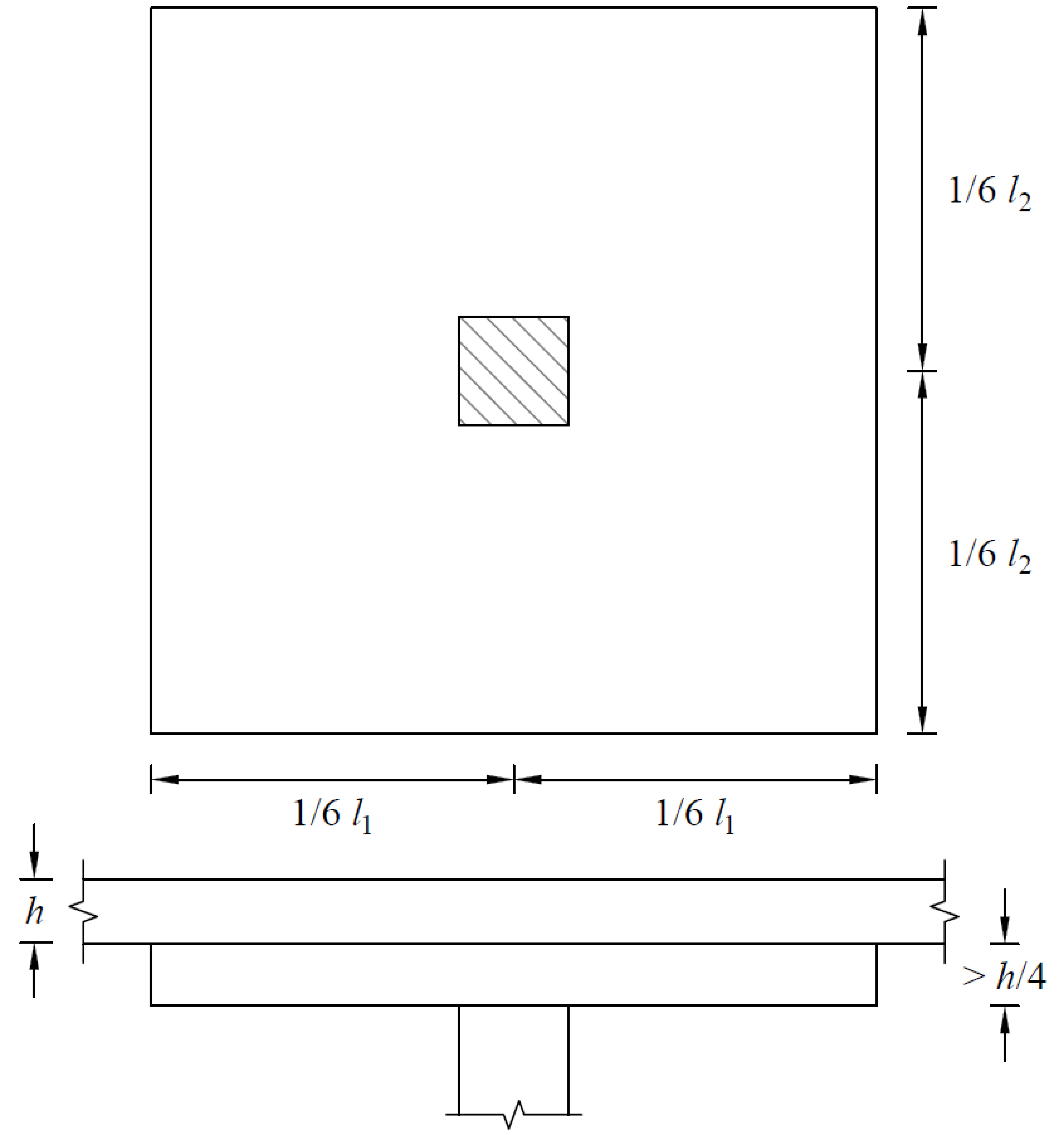
Figure 2.4 - Valid Drop Dimensions
The input drop dimensions will be used for self-weight computations, when computing slab stiffness to determine deflections, moments, shears, and when computing punching shear around a column19.
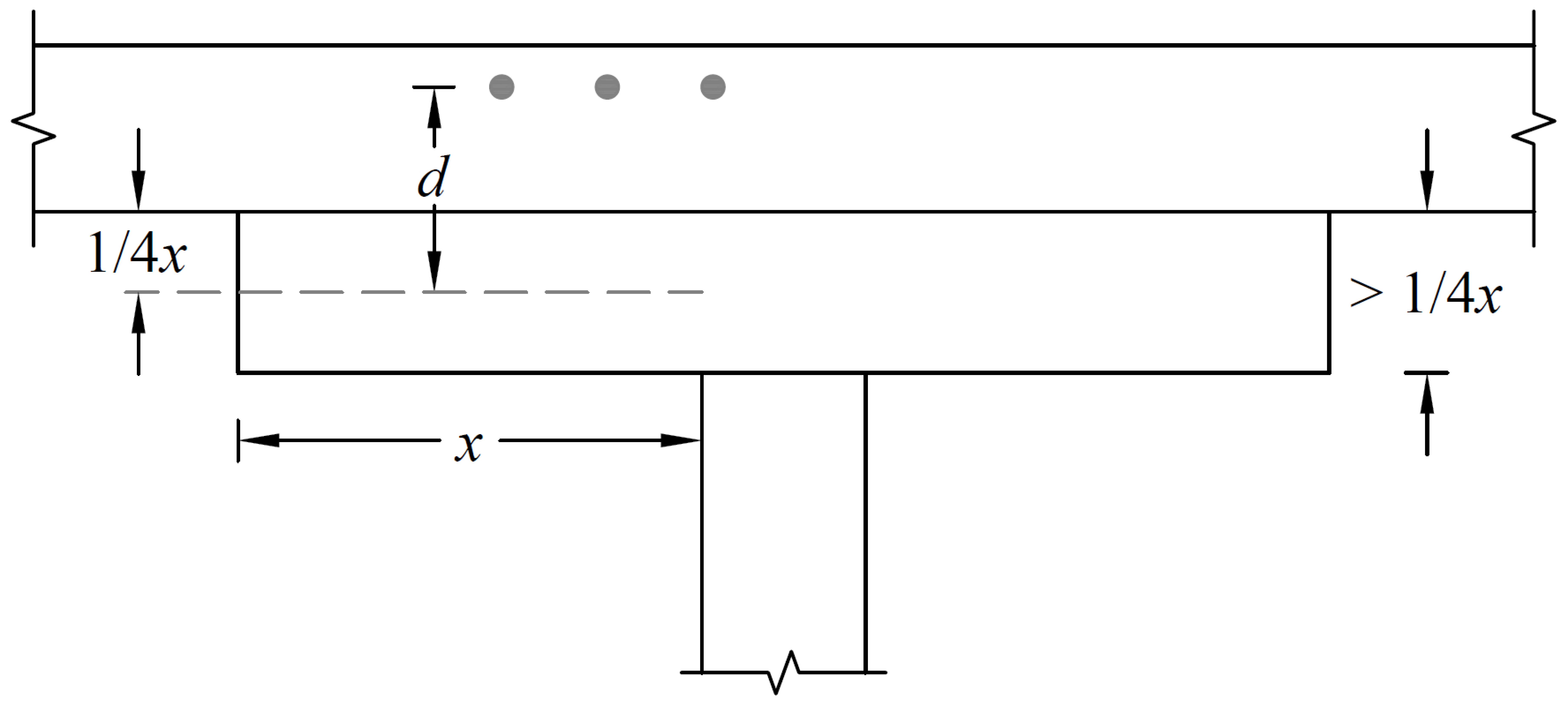
Figure 2.5 - Excess Drop Depth
The program follows linear distribution of strain (plain section) assumption20 for flexure design which is applicable to shallow flexural members. In case of deep beams21, design standards recommend using non-linear distribution of strain or strut-and-tie method. The program checks beam dimensions and if a beam with the following clear span, ln, to overall depth, h, ratio is found:
| Eq. 2-9 |
| |
| |
|

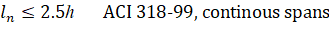
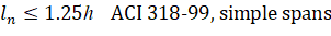

a warning is issued alerting the user that additional deep beam design and detailing is required. For cantilevers, the warning is issued only if their clear span is larger than overall depth.
2.2.1.2. Material Considerations
By entering the concrete density and compressive strength of the members, default values for the other concrete properties are determined. The slabs/beams and columns may have different concrete properties.
The density of concrete is used to determine the type of concrete, modulus of elasticity, and self-weight.
The concrete type is determined in accordance with Table 2.1.
Type | ACI 318-14 ACI 318-11 ACI 318-08 | ACI 318-05 ACI 318-02 ACI 318-99 | ||
wc | wc | |||
pcf | kg/m3 | pcf | kg/m3 | |
Normal | 135 ≤ wc | 2,155 ≤ wc | 130 ≤ wc | 2,000 ≤ wc |
Sand-Lightweight | 115 < wc < 135 | 1,840 < wc < 2,155 | 105 < wc < 130 | 1,700 < wc < 2,000 |
All-Lightweight | wc ≤ 115 | wc ≤ 1,840 | wc ≤ 105 | wc ≤ 1,700 |
Type | CSA A23.3-14 CSA A23.3-04 | CSA A23.3-94 | ||
γc | γc | |||
kg/m3 | pcf | kg/m3 | pcf | |
Normal | 2,150 ≤ γc | 134.2 ≤ γc | 2,000 ≤ γc | 124.8 ≤ γc |
Low Density | 1,850 < γc < 2,150 | 115.5 < γc < 134.2 | 1,700 < γc < 2,000 | 106.1 < γc < 124.8 |
Semi-low Density | γc ≤ 1,850 | γc ≤ 115.5 | γc ≤ 1,700 | γc ≤ 106.1 |
Table 2.1 - Concrete Weight Classification
Once the compressive strength of concrete fc′ is input, various parameters are set to their default values.
The modulus of elasticity is computed as22:
| Eq. 2-15 |
where: | ||
• wc | = | the unit weight of concrete. |
For CSA A23.3 standard23:
| Eq. 2-16 |
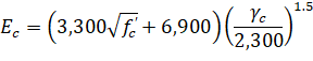
where: | ||
• γc | = | the density of concrete. |
The square root of fc′ is limited to 100 psi for the computation of shear strength provided by concrete, Vc, and development lengths.24
For CSA A23.3-14/04 standard the value of square root of fc′ used to calculate factored shear resistance vr shall not exceed 8 MPa.25
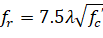
The modulus of rupture is used to determine the cracking moment when computing the effective moment of inertia in deflection calculations. For ACI 318 code, the default value of modulus of rupture, fr, is set equal to:26
| Eq. 2-17 |
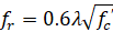
and for the CSA A23.3 standard, the default value of modulus of rupture fr is:27
| Eq. 2-18 |
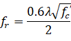
For two-way slabs analyzed in accordance with CSA A23.3-94 as well as for beams, one-way, and two-way slabs analyzed in accordance with CSA A23.3-14/04, the default value is reduced to its half value28, i.e.
| Eq. 2-19 |
Factor λ reflecting the reduced mechanical properties of lightweight concrete is equal to29:
| Eq. 2-19 |
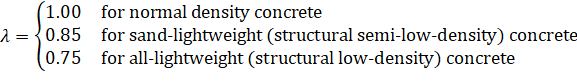
Refer to Table 2.1 for determination of concrete type.
There is no limit imposed on fr. Entering a large value of fr will produce deflections based on gross properties (i.e. uncracked sections).
The default values for the longitudinal reinforcement yield strength, fy, and shear reinforcement yield strength, fyv, if applicable, are set equal to 60 ksi [413 MPa] for ACI and 400 MPa for CSA.
2.2.1.3. Loading Considerations
Load Cases and Load Combinations
Each load is applied to the span element under one of the 6 (A through F) load cases. The span element is analyzed and designed under load combinations. A load combination is the algebraic sum of each of the load cases multiplied by a load factor.
The program allows defining up to 50 load combinations. The user has full control over the combinations. The program contains predefined (built into the program) default primary load combinations for the supported codes. These default combinations are created when starting a new project.
For the design of span elements, the required area of steel is calculated due to the element internal forces from the ultimate level combinations. On the other hand, displacement envelopes are determined using the displacement from the service level combinations.
Basic load cases and the corresponding load factors for load combinations are provided as defaults to facilitate user’s input. The default load cases and load combination factors should be modified as necessary at the discretion of the user.
Given the numerous applications of spSlab/spBeam to structural floor systems, the load combinations must be examined in detail to consider the myriad of possible conditions that can exist. A detailed discussion of load case and combination factors is provided in Appendix A.1.
The evaluation of floor systems requires consideration of various live load configurations to capture the critical effects on structural responses. To address these scenarios, the program automatically generates live load cases using predefined patterns. The program also incorporates a live load pattern reduction ratio, defaulting to 75% for two-way systems per code requirements, with user customization available between 0–100%. A detailed discussion of load patterns is provided in Section 2.3.3.4.
Off-Centered Loads for Two-Way Slabs
For two-way slab systems, the distribution of loads along the analysis direction becomes simplified while utilizing the Equivalent Frame Method (EFM), eliminating the need to consider additional torsion and moments for “Off-Centered” loads. The following figure highlights how different load types - uniform distributed loads (A), concentrated loads (B), and line loads (C) - are translated into equivalent load input values for spSlab. Each load is converted into the corresponding program input format, ensuring accurate representation of the structural behavior. This approach streamlines the modeling process while maintaining the integrity of the applied loads in the analysis. It is critical that the engineer and user exercise maximum judgment in this area based on his thorough understanding of the EFM and how its application in two directions should be managed. The simplification of taking a two-way concrete floor system and breaking it into two individual one-way systems should not overlook how the overall system will ultimately behave. As such, loads handled in one direction will have to also be reconsidered in the orthogonal direction where they may present a more governing condition.
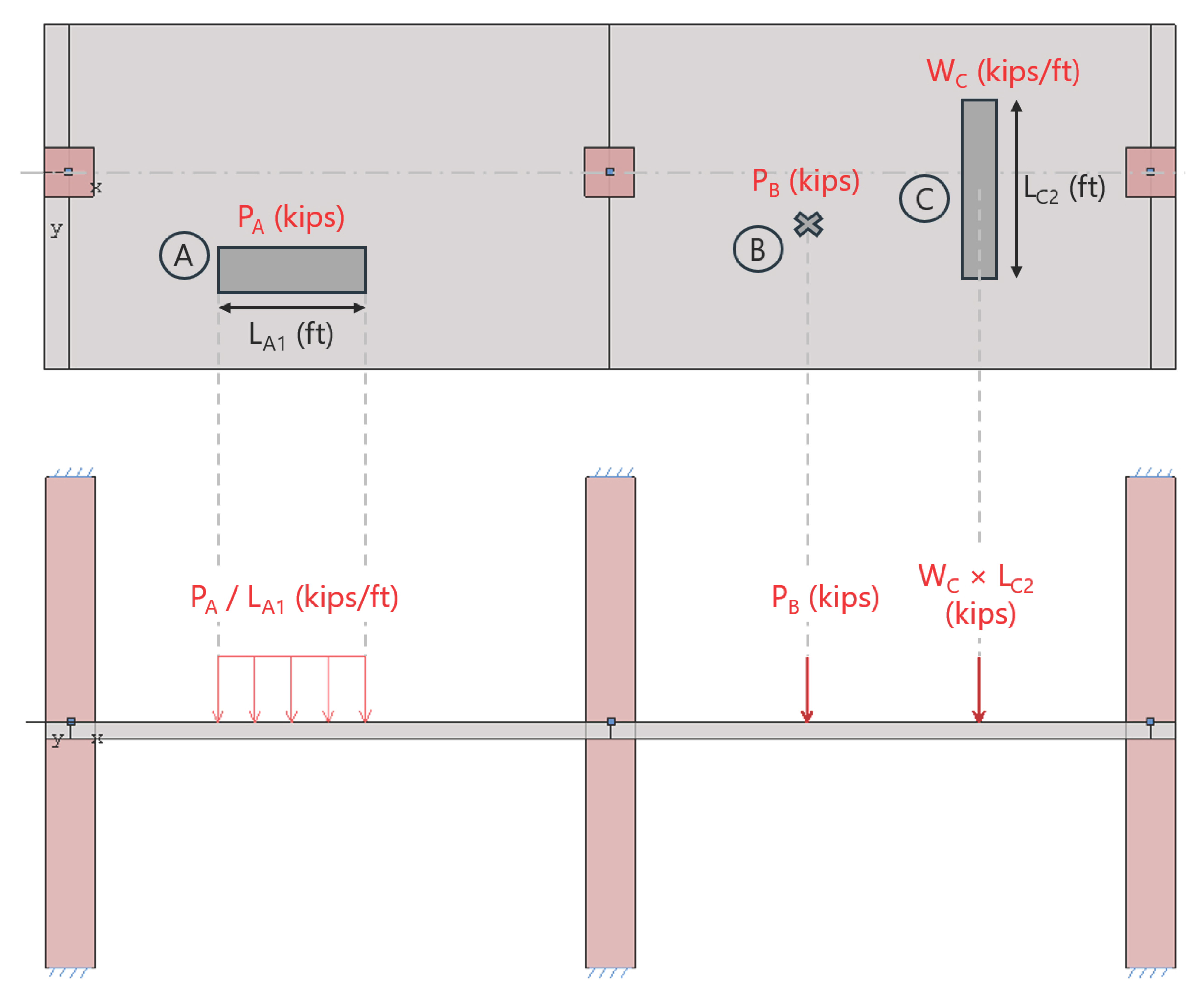
Figure 2.6 - Entering “Off-Centered” loads into spSlab model as equivalent load input
When a floor system contains an opening, usually it is due to an important Mechanical, Electrical or Piping (MEP) equipment that are passing through such opening. As such, the presence of the opening complicates the analysis using the EFM. The engineer has to consider the absence of some or an entire part of the column strip or the middle strip. In addition, the additional loads from attachments borne by the MEP equipment or stairs or any other accessories have to also be added to an area that is already compromised by the opening. Such loads are commonly concentrated point loads that are close or in direct contact with the support creating concentrated shear forces that have to be handled carefully depending on their proximity to the support.
The impact of such floor openings and concentrated forces on the shear force and bending moment diagrams and ultimately the reinforcement required will depend greatly on a number of variables that are difficult to quantify, nor are they clearly explained in the current codes and standards.
StructurePoint's experience indicates that occasionally engineers have to forego the intended two-way behavior and resort to one-way action in certain spans or in an entire design strip. In some instances, additional beams and framing should be added to accommodate such loss of section and the concentration of forces. The engineering end-user is advised to e-mail and contact StructurePoint's experts to discuss such conditions and find the proper application of the EFM to model their floor system in spSlab to that specific condition.
2.2.1.4. Special Considerations for Joist Systems
The following considerations are applicable to one-way (standard and wide module) and two-way (waffle) joist systems unless noted. More details about this topic can be found in “Two-Way Joist Concrete Slab Floor (Waffle Slab) System Analysis and Design” and “One-Way Wide Module (Skip Joist) Concrete Floor System Design” Design Examples from StructurePoint.
Rib dimensions will be considered valid if the rib width is at least 4 in. [100 mm], the depth is no more than 3-1/2 times the rib width, and the clear spacing between ribs does not exceed 30 in. [800 mm]30. If rib dimensions do not meet these requirements (e.g. wide module joist systems) the code requires such ribs to be designed as beams31. The program treats the design of wide-spaced joists the same way as for valid slabs, regardless of code limitation. If the code limits are exceeded, the condition is flagged and the 10% increase of rib shear capacity is not used. The user is then responsible to validate the resulting design and reconcile the code requirements.
Minimum Thickness for Joist Systems
The minimum slab thickness allowed for joist slabs is one-twelfth the clear rib spacing, or 1.5 in. [40 mm] for ACI code32 and 50 mm for CSA code33.
Joist System Analysis and Design
For the purposes of analysis and design, the program replaces the ribbed slab with solid slabs of equivalent moment of inertia, weight, punching shear capacity, and one-way shear capacity.
The equivalent thickness based on system weight is used to compute the system self-weight. This thickness, hw, is given by:
| Eq. 2-10 |

where: | ||
• Vmod | = | the volume of one joist module, |
• Amod | = | the plan area of one joist module. |
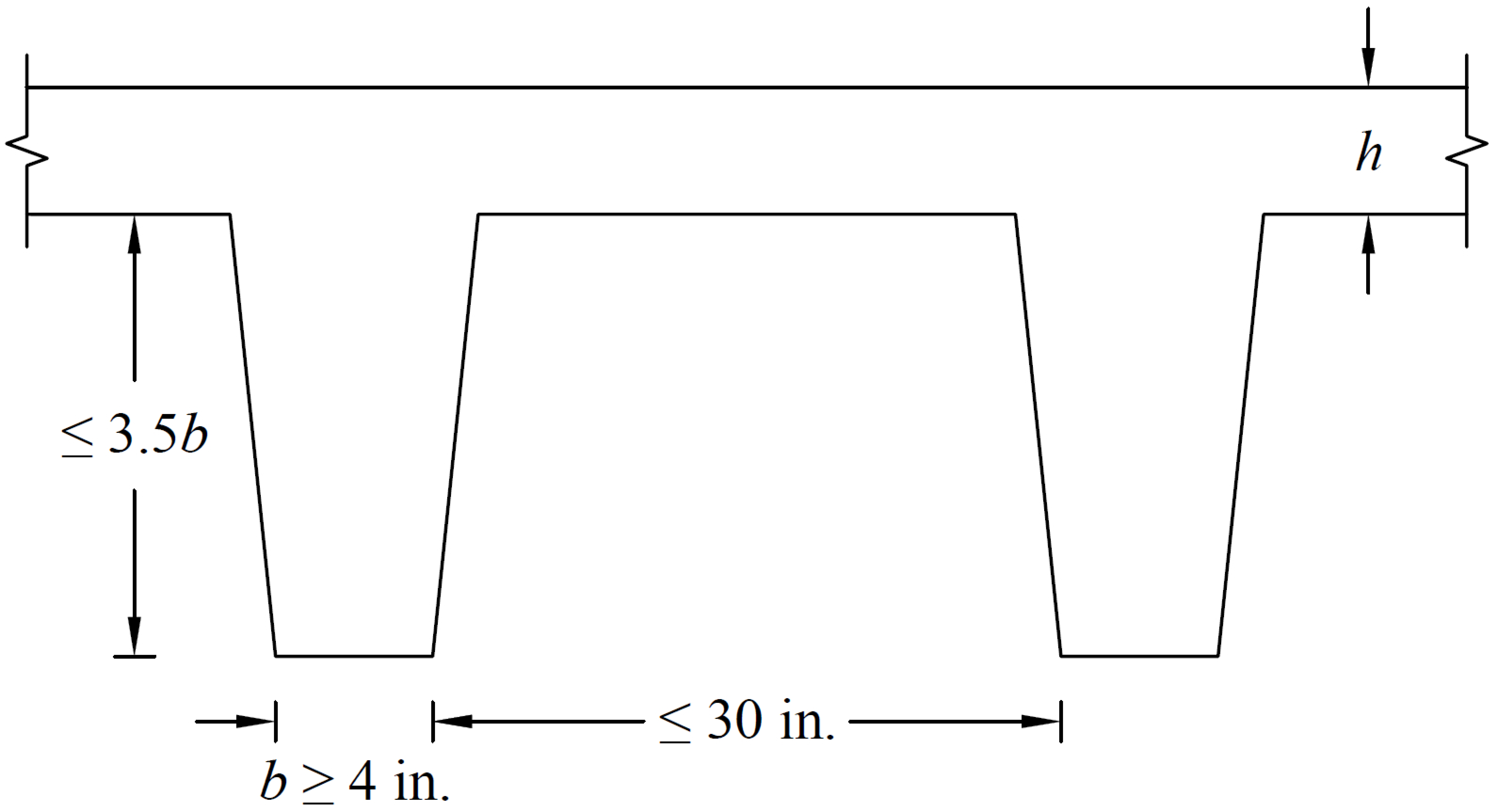
Figure 2.7 - Valid Rib Dimensions
The equivalent thickness based on moment of inertia is used to compute slab stiffness. The ribs spanning in the transverse direction are not considered in the stiffness computations. This thickness, hMI, is given by:
| Eq. 2-11 |
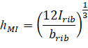
where: | ||
• Irib | = | moment of inertia of one joist section between centerlines of ribs, |
• brib | = | the center-to-center distance of two ribs (clear rib spacing plus rib width). |
The drop panel depth for two-way joist (waffle) slab systems is set equal to the rib depth. The equivalent drop depth based on moment of inertia, dMI, is given by:
| Eq. 2-12 |
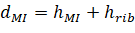
where: | ||
• hrib | = | rib depth below slab, |
• hMI | = | equivalent slab thickness based on moment of inertia. |
A drop depth entered for a waffle slab system other than 0 will be added to dMI, thus extending below the ribs.
One-way shear capacity, Vc (increased by 10% for ACI code34), is calculated assuming the shear cross-section area consisting of ribs and the portion of slab above, decreased by concrete cover. For such section the equivalent shear width of single rib is calculated from the formula:
| Eq. 2-13 |

where: | ||
• b | = | rib width, |
• d | = | distance from extreme compression fiber to tension reinforcement centroid. |
The equivalent thickness based on shear area is used to compute the area of concrete section resisting punching shear transfer, Ac around drop panels in two-way joist (waffle) systems. The equivalent slab thickness, hV, used to compute Ac, is given by:
| Eq. 2-14 |
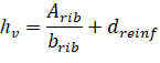
where: | ||
• Arib | = | the entire rib area below the slab plus the slab thickness minus the distance to the reinforcement centroid, dreinf, within the rib width, i.e., the slab depth between the ribs is not considered as contributing to shear capacity, |
• brib | = | the center-to-center distance of two ribs (clear rib spacing plus rib width), |
• dreinf | = | the distance to reinforcement centroid from the slab top at the support. |
When calculating flexural capacity for negative bending moments, the distance between center of top reinforcement to the soffit of the rib is used as an effective depth, d, while assuming the width of compression zone as equal to the center-to-center distance of two ribs (brib). This assumption results in higher estimates of negative moment capacity since the space between ribs is void. The user may switch to a single rib design or investigation as a beam in order to consider rib width only in the compression zone.
spSlab and spBeam provide various geometric checks to avoid an analysis with an inconsistent system. Dimensions of slabs, beams, drops, bands and column capitals are checked and modified to produce a code compliant system.
If a slab cantilever length is less than one-half the column dimension in the direction of analysis, c1, or less than the lateral extension of the transverse beam into the cantilever, the cantilever length will be increased to the larger of these two lengths. If the slab width is less than one-half the column dimension transverse to the direction of analysis, c2, or less than one-half the longitudinal beam width, the slab width will be increased to the larger of these two widths.
If a drop panel extends beyond the end of a slab cantilever, the drop panel dimensions will be reduced so that it extends only to the cantilever tip.
Guidance is absent from all standards and reference documents regarding continuous extension of drop panels between supports. If a slab band is discontinuous, to model this condition, it must be completed with a user-defined drop panel of corresponding width and thickness on a discontinuous end, as a minimum, in order to complete the analysis.
When a column capital is defined, the program checks if capital side slope (depth/extension ratio) is more than 1, i.e. the angle between capital side and column axis is no greater than 45 degrees35. The upper limit for the side slope is 50. If a column with capital frames into a drop panel (or a beam), extension of the capital will be automatically adjusted – if necessary – so that projected sides of the capital do not fall outside of the drop panel (or the beam) edges before reaching slab soffit (see Figure 2.8). The modified column capital extension will be used when computing column stiffness and in punching shear calculations.
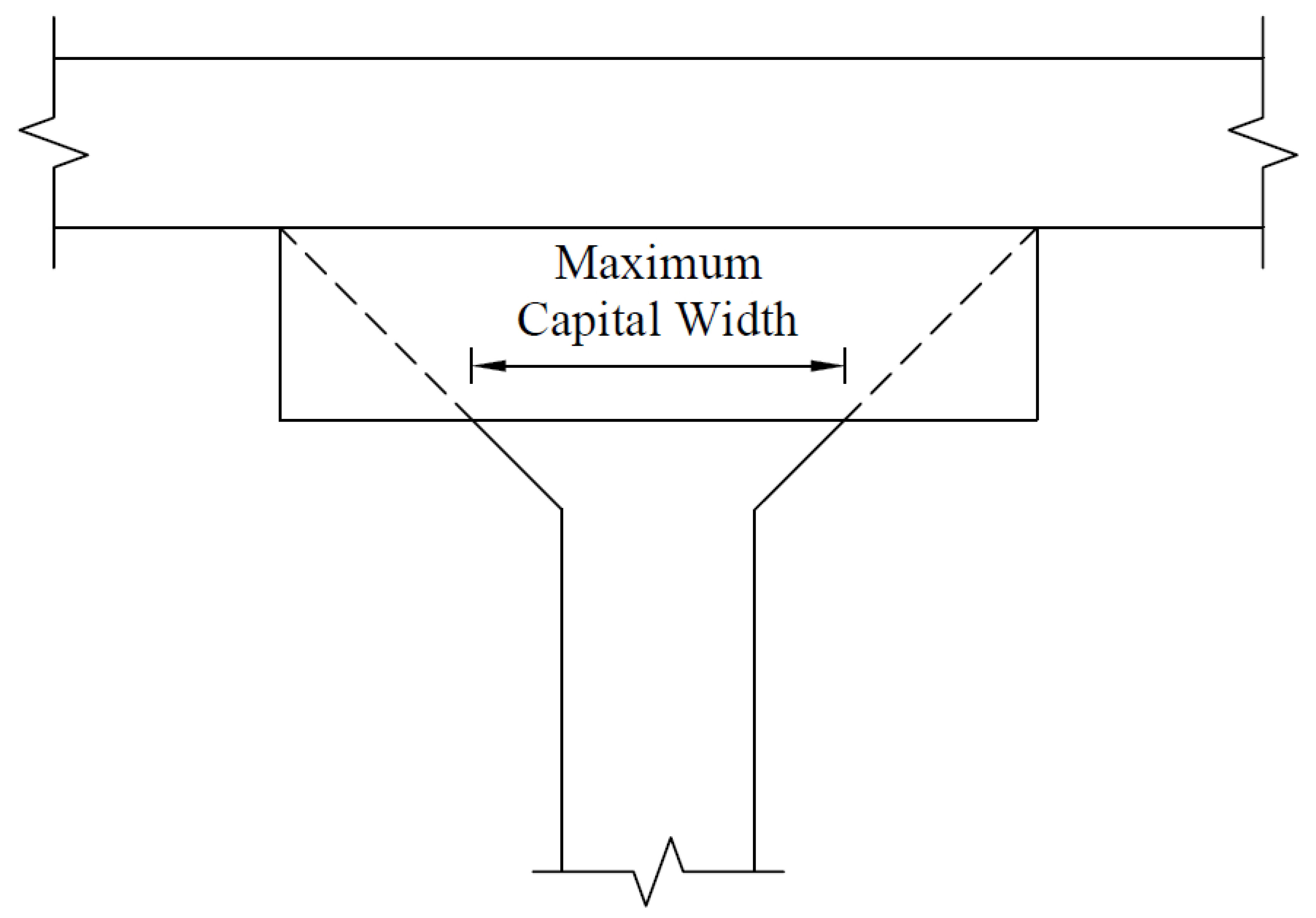
Figure 2.8 - Maximum Capital Width
2.2.3. Definitions and Assumptions
The analysis of the reinforced concrete members performed by spSlab/spBeam conforms to the provisions of the Strength Design Method and Unified Design Provisions and is based on the following basic assumptions:
• All conditions of strength satisfy the applicable conditions of equilibrium and strain compatibility
• Strain in the concrete and in the reinforcement is directly proportional to the distance from the neutral axis. In other words, plane sections normal to the axis of bending are assumed to remain plane after bending.
• An equivalent uniform rectangular concrete stress block is used with a maximum usable ultimate strain at the extreme concrete compression fiber equal to 0.003 for ACI codes and 0.0035 for CSA codes
• Tensile strength of concrete in flexural calculations is neglected
• For reinforcing steel, the elastic-plastic stress-strain distribution is used
• Assumptions related to the analysis method, along with detailed provisions and equations for the design codes and unit systems supported by spSlab/spBeam, are outlined in Sections 2.3, 2.4, and 2.5.