The key to effectively implementing spSlab/spBeam in a project is understanding the program’s robust approach to modeling, analyzing, designing, and evaluating reinforced concrete slabs and beams under a variety of loading conditions. Of utmost importance is the understanding of the methods utilized in the program for the analysis of reinforced concrete floor slab systems. This section provides insights into the methods, assumptions, and factors that the design professional must consider while modeling using spSlab/spBeam for analysis, design, and detailing.
As a foundational guideline, the geometry of the analytical model should represent the physical structure as closely as possible to ensure accurate analysis results.
Users must confirm that the project criteria align with applicable design codes and standards. This includes considerations for load types, load factors, load combinations, material properties, reinforcement requirements, deflection criteria, and detailing provisions, ensuring compliance with industry standards and best practices.
4.1.1. Physical Modeling Terminology
In spSlab, the terminology around elements and members is critical for understanding how the program models reinforced concrete slabs and beams. spSlab utilizes elements to represent structural components in the Equivalent Frame Method (EFM). Elements are the primary modeling units within spSlab, corresponding closely to the physical structural members in the project. The EFM is a very well established analysis method used exclusively for two-way concrete floor systems. In this method, a great variety of floor systems are covered in its scope. As a result. Many structural elements contribute to the making of a concrete floor system. These elements allow users to capture the geometry and material properties of slabs, beams, slab bands, columns, drop panels, and column capitals within the analytical model. These elements are used at the engineer's discretion to combat design challenges pertaining to one-way shear, two-way shear, inadequate flexural strength, or unacceptable deflections.
The EFM in spSlab simplifies modeling by focusing on frame strips representing the slab-beam-column system. Users only need to define the primary elements, which spSlab discretizes into equivalent frame members for analysis. This streamlined modeling method saves time and simplifies the design process.
By using the EFM, spSlab enables both efficient modeling and accurate structural behavior prediction without requiring more elaborate and intricate analysis processes such as the Finite Element Method (FEM) of analysis. Instead, users can focus on defining element properties and ensuring that the geometry of the analytical model accurately reflects the physical structure.
It is crucial to understand the concept of elements in spSlab, as it forms the foundation for creating effective and efficient models. Once familiar with this approach, users can appreciate the simplicity and power of the EFM in modeling complex slab and beam systems.
The spSlab program uses elements to represent physical structural members. When creating a model, users begin by defining the geometry of slabs, beams, and other structural elements within the program using drawing area common Computer-Aided Design (CAD) tools and then assign properties and loading to these elements, fully specifying the structural model for analysis.
To complete the model of a concrete floor system, two essential element types are required in spSlab:
• Span Elements: Used to represent slabs, longitudinal beams, ribs, and longitudinal slab bands.
• Support Elements: Used to represent columns, drop panels, column capitals, transverse beams, and restraints.
As a general rule, the geometry of each element should represent that of the actual physical member as closely as possible. This approach enhances visualization of the model and reduces potential errors during input. However, engineers can omit small changes in shape and geometry where added model accuracy or complexity is not consequential to the analysis & design results. A great deal of engineering judgment is involved in the conversion of a physical structure into an analytical model. However, significant gains can be achieved by keeping model simple & practical to the extent possible.
It is also essential that beginner users must establish smaller simpler models at first to gain a better understanding of the program and its features. This will help greatly in understanding the method of solution as well as figure out what to do when there is an issue to diagnose or verify in the output. It is always much easier to discover the source of an error when working with a simple model and a few loading conditions. Once a model becomes complicated with numerous loads and load combinations, it becomes increasingly difficult to discover the source of an issue or a concern in the output, graphical or tabular.
Material and geometric properties for model elements in spSlab and spBeam are categorized into two groups: Defined Properties and Unique Properties. This distinction provides users with the flexibility to manage elements properties consistently across the model while accommodating variations for specific spans and supports.
Defined Properties refer to material properties, including concrete material properties (compressive strength fc′, unit density Wc, Young's modulus Ec, and rupture modulus fr), and reinforcing steel material properties (yield stress for flexural steel fy, yield stress for stirrups fyt, and Young's modulus Es). Concrete material properties are consistent across all slab and beam elements but can differ for column elements, allowing for tailored input to reflect different structural requirements. Reinforcing steel material properties, however, remain the same throughout the model, including slabs, beams, and columns, ensuring uniformity in reinforcing steel characteristics. The program enables users to define these properties globally, maintaining consistency and alignment with design standards such as ACI 318 and CSA A23.3, while accommodating necessary distinctions between slabs, beams, and columns where applicable.
Unique Properties, on the other hand, refer to element geometric properties that are specific to individual spans and supports. These properties (such as slab/beam width, thickness, column width, depth, or height) are assigned on a per-element basis, enabling the program to account for variations in geometry that influence structural behavior. Each span and support can therefore have distinct geometric attributes, allowing for a more refined and realistic representation of the structure.
If you do not find a suitable template to begin your project, you can start with a blank project. A blank project requires a lot more care in the construction of the model and much more effort to complete the details of the input. To begin, start by setting up the grids in the Grid command to define the layout. Next, use the Spans command to add slab, beam, or rib elements and adjust their dimensions as needed. Finally, use the Supports command to add support elements such as columns, beams, or restraints, and configure their properties, including height, size, and end conditions. The following guidelines can be used in this scenario:
• To establish a comprehensive model for structural analysis, the user begins by defining grids and specifying span lengths to ensure an accurate layout representation. If the span lengths need to be adjusted later, the user can return to the Grid command and modify the span lengths using the Span table.
• The user must define frame location and evaluate which location best aligns with the design intent. Detailed insights and guidance on selecting appropriate frame location can be found in Section 5.2.2.4 of the manual.
• A critical decision involves addressing cantilever extensions - whether they function as true cantilevers (e.g., balcony or canopy projections) or are intended to encompass the column to contribute to two-way shear resistance. In the Span table under Grid command, users can select USER-DEFINED for cantilevers on the left and right to simulate a true cantilever or choose ADJUST TO SUPPORT FACE to encompass the column.
• Building on the selection of cantilever behavior, choosing ADJUST TO SUPPORT FACE in the Span table allows the cantilever to align its geometry with the support face. When selected, the program assigns a placeholder cantilever length of 5 ft until an exterior support is defined. If the model is run without assigning the required support, the process will be interrupted, and the program will display an error message, indicating the requirement for a column or transverse beam at the cantilever edge joint. The figure below illustrates this process.
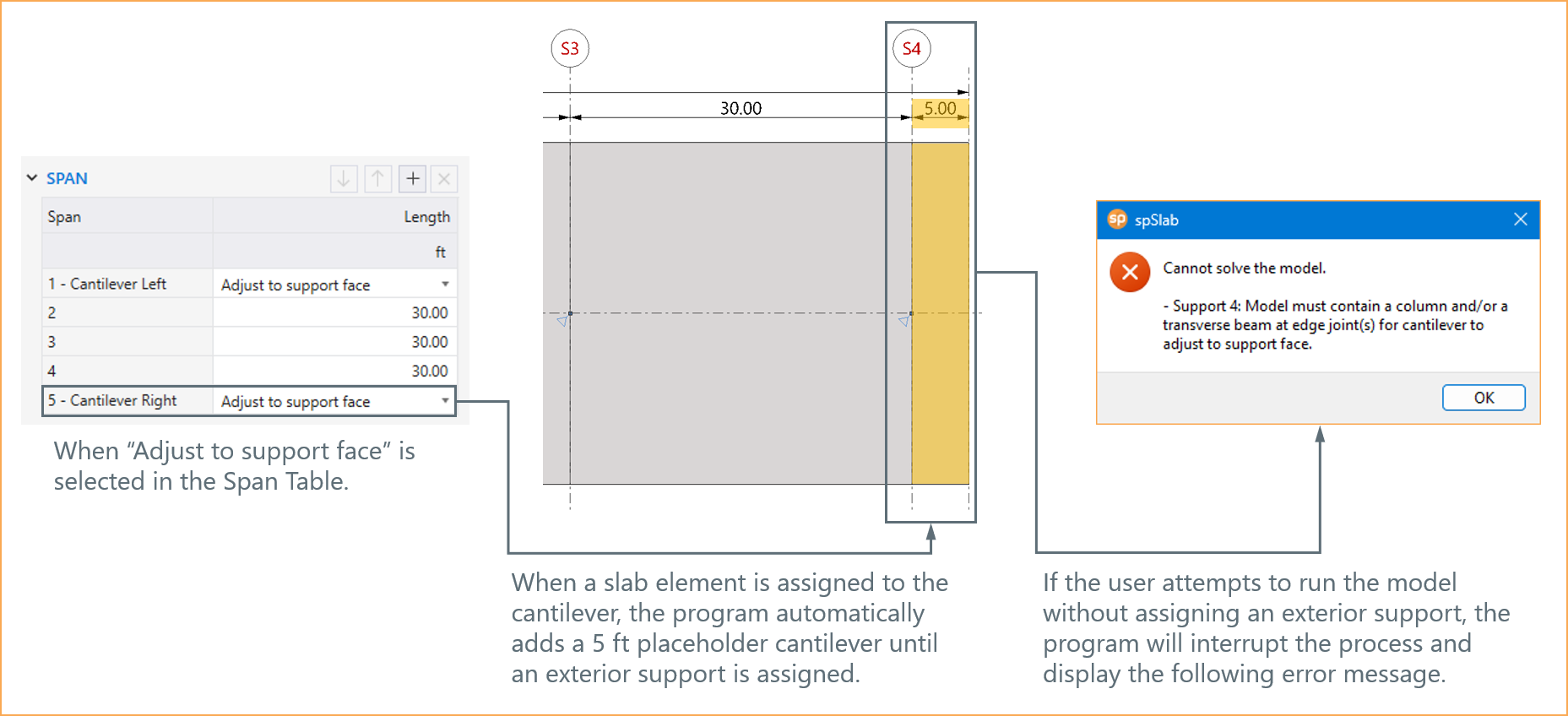
Figure 4.1 - Adjust to Support Face Option
• When NONE is selected for the right and left cantilevers in the Span table, the model assumes that no cantilever extensions are required. For that case, if the user runs the program without assigning any additional supports, the program will automatically assign default pin supports at the slab joints. This allows the model to run without interruptions, ensuring the structural analysis proceeds under simplified support conditions.
4.1.5. Modeling Considerations
4.1.5.1. Sway and Non-Sway Considerations
When considering sway versus non-sway conditions in structural analysis, it is essential to account for lateral effects in the model to ensure accurate results. In non-sway conditions, programs like spSlab and spBeam assume horizontal translational restraint, excluding lateral effects directly from the analysis. This approach simplifies the modeling process and is suitable for frames where lateral displacements are minimal or restrained, such as single-story frames with balanced vertical loads and consistent boundary conditions.
However, in sway conditions, where unsymmetrical vertical loading, support stiffness variations, or boundary conditions induce lateral movements, the lateral effects must be explicitly included. These can be added as member-end forces, such as moments acting at the ends of each span, using Lateral Load Effects, which can be assigned from the Lateral command in the Left Panel under Loads command. This allows users to input lateral loads like wind or seismic forces as moments at the ends of members, enabling the program to account for combined vertical and lateral effects accurately.
For cases where significant lateral displacements or sidesway effects are expected, it is recommended to use spFrame, which models the frame as a two-dimensional unit for the entire building height. spFrame accurately captures the influence of sidesway on internal force magnitudes, ensuring reliable results for design.
This dual approach - leveraging spSlab and spBeam for simplified non-sway analysis and spFrame for sway-sensitive scenarios - ensures flexibility and precision in addressing varying structural conditions. Additional details about this topic can be found in Section 2.6.10, Section 5.2.4.3, and "Comparison of Gravity Loaded Concrete Frame Models in spBeam and spFrame under Sidesway" Technical Article from StructurePoint.
4.1.5.2. Unbalanced Moments in Column Design
Unbalanced moments in a floor system play a critical role in the design of columns located above and below the slab-beam structure. These moments arise from the distribution of loads and are transferred from the slab to the support columns in proportion to their relative stiffness. This transfer creates forces in the columns, which must be accurately calculated and incorporated into their design to ensure structural integrity. Additional details about this topic can be found in Section 2.3.7.4.
Column end moments and axial forces can be found in the results table. These forces for various load combinations and live load patterns can be then exported to spColumn for detailed design or investigation of a column cross-section. StructurePoint prepared several design examples for a complete floor system including the calculation of unbalanced moments in columns and the investigation of column section reinforcing to provide the required strength in the column.
Detailed discussion of unbalanced moments in column design can be found in the following design examples from StructurePoint:
"Two-Way Flat Plate Concrete Slab Floor Analysis and Design" Section 2.2.7. and Section 3.
"Two-Way Flat Slab (Drop Panels) Concrete Floor Analysis and Design" Section 2.1.7. and Section 3.
"Two-Way Concrete Floor Slab with Beams System Analysis and Design" Section 2.7. and Section 3.
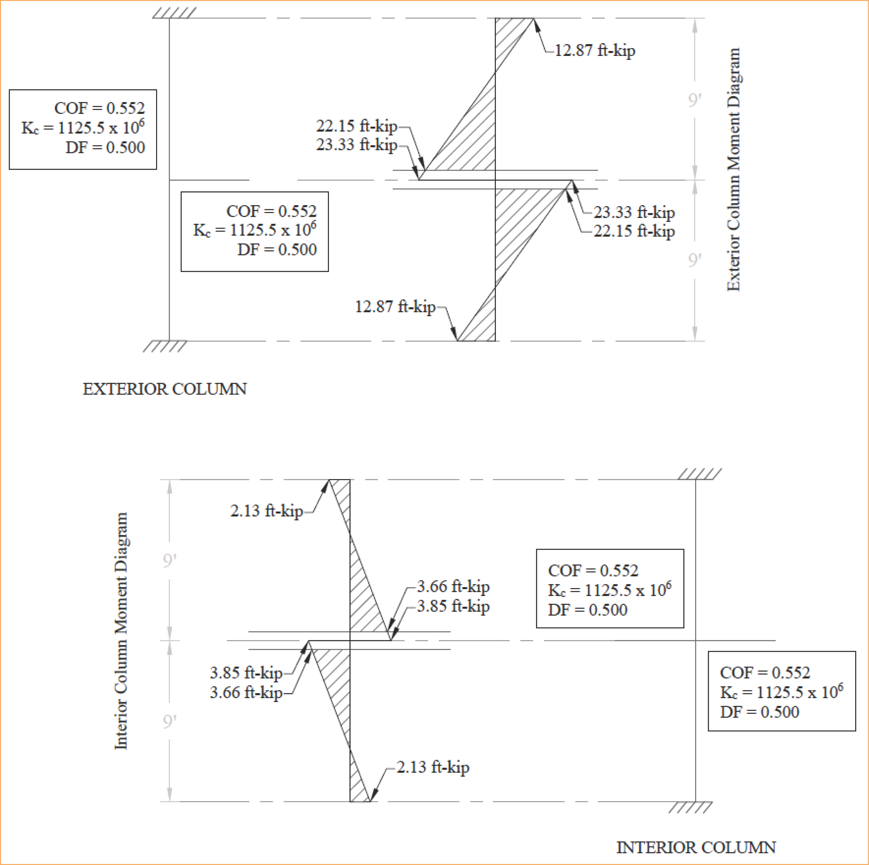
Figure 4.2 - Column Moments (Unbalanced Moments from Slab-Beam)
4.1.5.3. One-Way Slabs on Transverse Beams
In modeling one-way slabs supported by transverse beams, several important and consequential considerations must be addressed to ensure accurate analysis and design. The rotational resistance of exterior supports plays a significant role in moment distribution. Two common conditions are recognized:
• Unrestrained exterior supports: Treated as pin supports, they provide no rotational resistance at the slab end. This is the default assumption in spSlab/spBeam, with the rotational stiffness (Kry) set to zero.
• Integral exterior supports: Provide rotational resistance and are modeled as semi-rigid connections. For example, spandrel beams integrated with the slab can be assigned rotational stiffness approximated iteratively using design codes provisions or other sources for moment factors, offering a more realistic representation.
Additionally, modeling transverse beams or girders can incorporate their added stiffness, reducing the effective slab span and yielding a closer approximation to actual conditions. While this approach enhances the accuracy of moment distribution, it introduces additional modeling parameters, requiring careful engineering judgment. Additional details about this topic can be found in "One-Way Slab Analysis and Design" Design Example from StructurePoint.
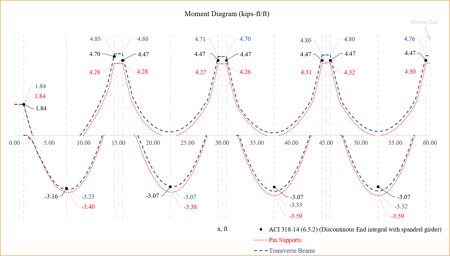
Figure 4.3 - One-Way Slabs on Transverse Beams
4.1.5.4. Boundary Condition Effects on Continuous Beam Deflections
Boundary conditions significantly influence the deflection behavior of continuous beams in reinforced concrete structures. Properly modeling these conditions in spBeam ensures accurate analysis and design results. This section explores the effects of different support conditions:
• Beam Supported by Columns: The stiffness of columns above and below the beam is modeled to calculate rotational stiffness at the joint. This accurately determines beam end moments. Support stiffness is adjustable, with values ranging from 0 (pinned) to 999 (fixed support), providing flexibility in simulating various boundary conditions.
• Beam Supported by Transverse Beams: Transverse beams are modeled using rotational stiffness values. ACI and CSA codes approximate moments at transverse beam supports as two-thirds of those at column supports. For more precise design, dummy columns can be used to define critical sections for shear and moment calculations.
• Beam Supported by Transverse Walls: Beams cast monolithically with shear walls are modeled as having walls defined as elongated columns to simulate integral behavior.
• Beam Supported by Masonry Bearing Walls: Masonry walls are modeled as pinned supports with zero stiffness, effectively simulating their bearing behavior without rotational constraints.
• Beam Supported by Longitudinal Walls: Beams are modeled up to the face of the wall with fixed supports at the wall face, ignoring wall width in the analysis.
Deflection comparisons highlight the variations due to boundary conditions. For example, beams with transverse beam supports show higher deflections compared to those supported by walls, emphasizing the importance of modeling boundary conditions accurately. For further details, refer to “Reinforced Concrete Continuous Beam Analysis and Design” Design Example from StructurePoint.
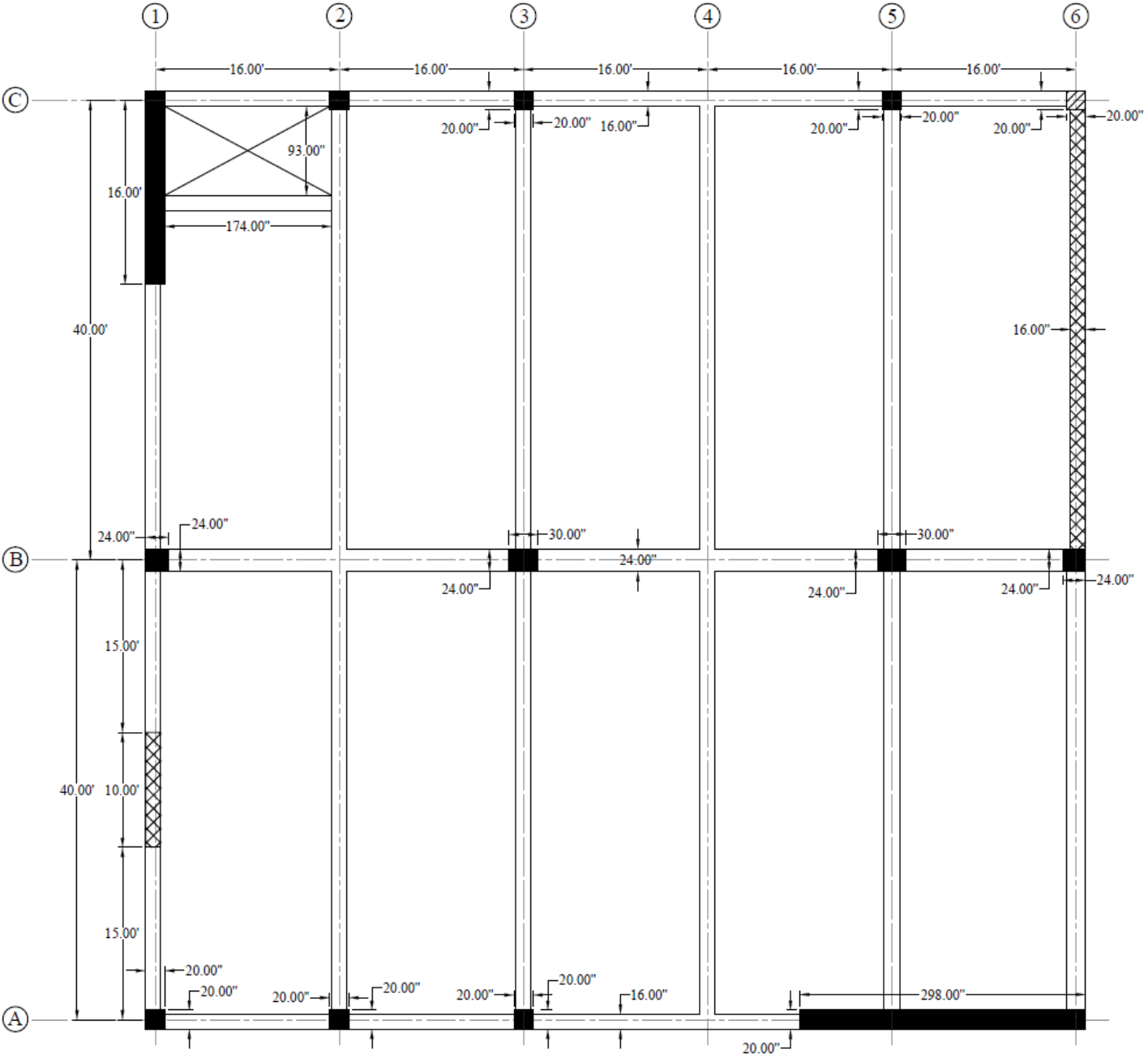
Figure 4.4 - Plan View of Continuous Beams with Different Boundary Conditions
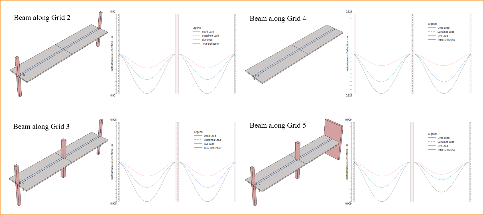
Figure 4.5 - Comparison of Continuous Beams with Different Boundary Conditions (Deflections)
4.1.5.5. Design of New Buildings vs. Investigation of Existing Buildings
In spSlab/spBeam, the modeling approach depends on whether the project involves the design of a new building or the investigation of an existing building. The program offers two distinct run modes to address these scenarios: DESIGN mode and INVESTIGATION mode.
In DESIGN mode, the program performs structural analysis and determines the required flexural, shear, and torsional reinforcement based on the selected design code. This mode is ideal for new structures, as it provides a baseline design that ensures compliance with applicable codes and standards.
In INVESTIGATION mode, the user inputs the existing flexural, shear, and torsional reinforcement. The program then evaluates the adequacy of the provided reinforcement given the section shape and material properties used. This mode is particularly suited for assessing the safety and performance of existing structures or making modifications to them.
Even for investigations, it is recommended to initially use DESIGN mode to establish a reinforcement baseline that aligns with current codes. This design output can then serve as a starting point for further analysis and refinement in INVESTIGATION mode, ensuring consistency and accuracy throughout the modeling process. For detailed guidance, refer to Section 5.2.3.2 and 5.2.4.4.
4.1.5.6. Modeling and Design of T-Beams
In spSlab/spBeam, T-beams are modeled to account for the contribution of flanges, which can be formed either by monolithic casting of slabs and beams or as isolated T-beams, such as precast elements. The inclusion of flanges enhances structural performance by utilizing the flange as part of the flexural member, improving both strength and efficiency.
One advantage of flanges in T-beams is their ability to increase the compression area, boosting the beam's flexural capacity without requiring significant additional reinforcement. This makes T-beams highly effective for handling larger moments compared to rectangular beams. Another advantage lies in material efficiency. In T-beams, integrating the slab as part of the beam section reduces the concrete and steel required for the same structural capacity.
Shear design for T-beams can be more complex due to the nonuniform stress distribution in the web caused by the flange. This requires careful modeling and analysis to ensure accurate results. For precast T-beams, connection details between the beam and the surrounding structure must be considered to achieve the intended performance. Proper construction practices are crucial in both cases. For monolithic T-beams, ensuring the slab and beam are cast together effectively is essential for accurate structural behavior. For precast T-beams, the quality of the connections and proper alignment during installation are critical.
In spSlab/spBeam, flange dimensions and configurations are defined during modeling using the Spans command. Additionally, users can engage relevant code provisions for T-beam analysis, design, and deflection calculations through the Design Options and Deflection Options available under the Solve command. These features provide flexibility and precision in modeling and designing T-beams in accordance with applicable standards.
StructurePoint has prepared a number of T-beam case studies to assist in understanding the complexity of this important structural element. These cases illustrate the number of ways to handle the flexural design given single or doubly reinforce configurations as shown in the following table.
Case Study | Description | Notes |
• Rectangular Section Behavior • Singly reinforced | • The stress block depth “a” is less than the flange thickness • 2 layers of tension reinforcement | |
• T-Section Behavior • Singly reinforced | • The stress block depth “a” is more than the flange thickness • 2 layers of tension reinforcement | |
• T-Section Behavior • Singly reinforced | • The stress block depth “a” is more than the flange thickness • 3 layers of tension reinforcement | |
• Rectangular Section Behavior • Singly reinforced | • The stress block depth “a” is less than the flange thickness • 3 layers of tension reinforcement • 1 layer of compression reinforcement | |
• T-Section Behavior • Doubly reinforced | • The stress block depth “a” is more than the flange thickness • 3 layers of tension reinforcement • 1 layer of compression reinforcement |
Table 4.1 - StructurePoint T-Beams Case Studies
4.1.5.7. One-Way Slab System Considerations
In spSlab/spBeam, users have the option to model span elements as either slabs or beams; however, it is crucial to exercise sound engineering judgment to select the appropriate span element type. While the program permits the use of beam elements to model a one-way slab system, users must understand the implications of this choice, particularly concerning design code requirements.
Design codes, such as ACI 318 and CSA A23.3, differentiate between the minimum reinforcement ratios for slabs and beams. When modeling one-way systems, it is advisable to use slab elements for components behaving as slabs and reserve beam elements for structural members specifically designed as beams. Misusing these span elements may lead to incorrect reinforcement calculations as well as impact shear strength and deflection estimates.
spSlab/spBeam empowers users with the tools to model various structural configurations but relies on the engineer’s expertise to ensure the modeling choices align with the intended design purpose and applicable standards.
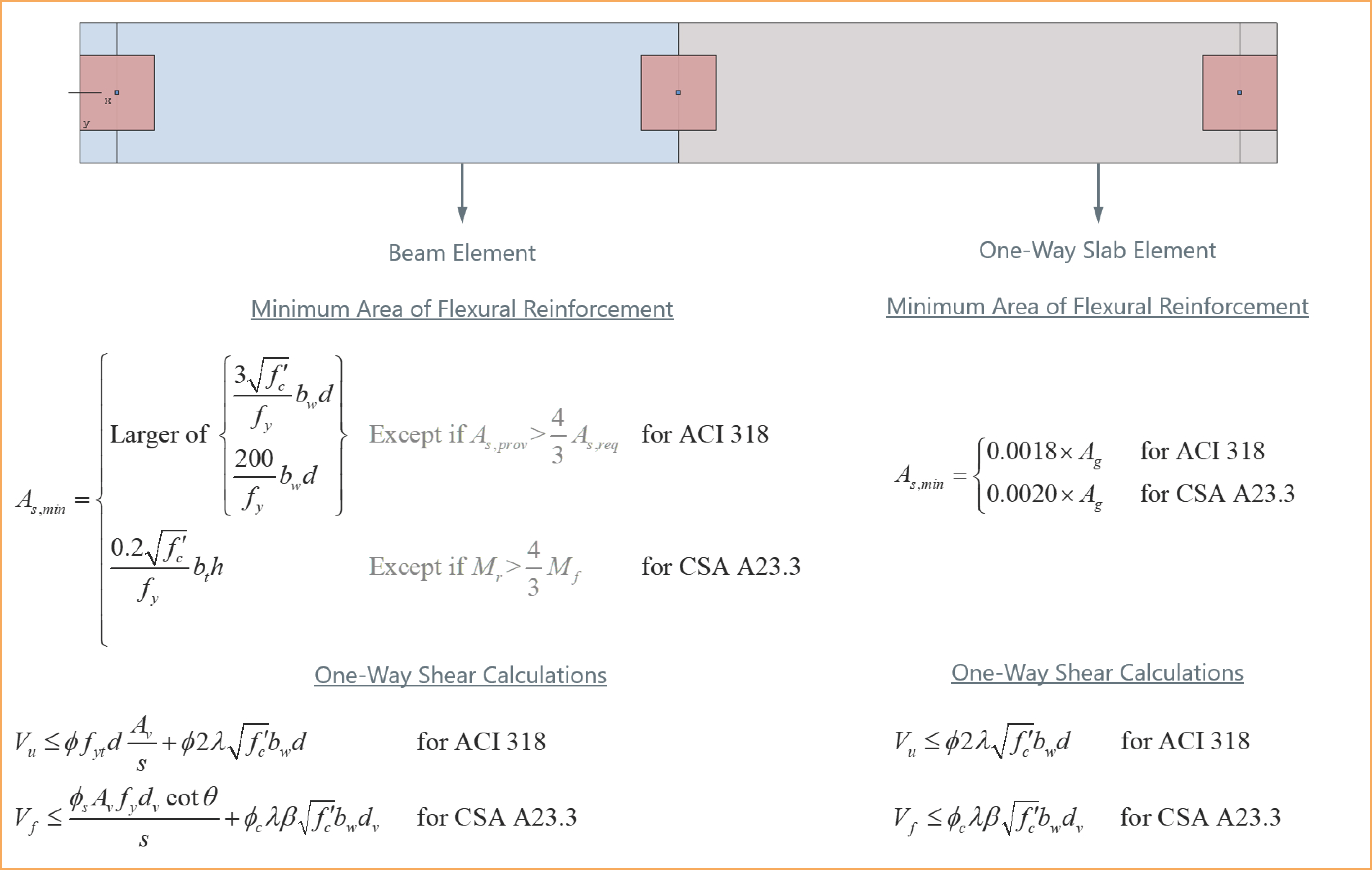
Figure 4.6 - Modeling Span Elements as Either Slabs or Beams