Conventionally reinforced concrete floor systems, including slabs and beams, contain a diverse variety of parameters and considerations that could be achieved by the flexibility of cast-in-place concrete forming systems. Notwithstanding prestressing and post-tensioning, engineers and design professionals will encounter numerous special conditions to handle and deal with in the design of a concrete floor system, ranging from the placement of concrete to optimizing of shapes and cross sections for gravity and lateral load effects.
2.6.1. Lateral Load Effects & Restraint
When analyzing lateral loads, each frame may be evaluated as a single unit for the full height of the building. Structural analysis software, such as spFrame and ETABS, can be used to perform this type of analysis. It is important to recognize that for lateral load assessment, slab-beam elements may experience reduced stiffness due to cracking, along with modifications to the effective slab width used in the analysis.
The bending moments generated at the two ends of a span due to lateral loads, such as wind or seismic forces, can be obtained from such an analysis. These moments can then be incorporated into the spSlab model as Lateral Load Effects input, allowing for the determination of the appropriate design moments when considering both gravity and lateral loading.
The scope of lateral load consideration in spSlab is limited to this process, where externally computed lateral moments can be applied within the equivalent frame model to evaluate their effects on the structural design as shown in the following figure. More information about this topic can be found in Section 2.3.3.3 and Section 5.2.4.3.
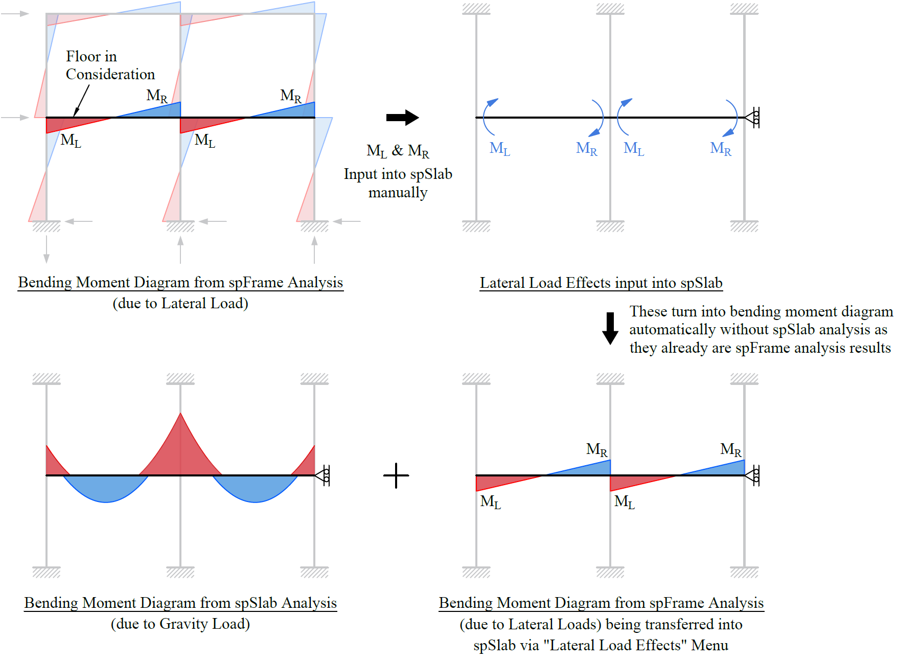
Figure 2.31 - Incorporation of Bending Moments due to Lateral Loads from spFrame into spSlab Gravity Load Analysis
2.6.2. Loads Along the Span Imposed by Lateral Loading
In some conditions, lateral loads acting on an equipment supported on a span may impose point loads and/or moments in that given span. The Program does not have a lateral type span load option in order to accommodate such point forces or moments at a span due to lateral loads. Although it is neither ideal nor recommended, the user may consider utilizing Snow load case to enter point forces or moments imposed by such lateral loads along the span in order to obtain the internal forces and for the flexural and shear design purposes. In the Program, since Snow load case is a Dead load type, its implications to deflection calculations would require considerable engineering judgment.
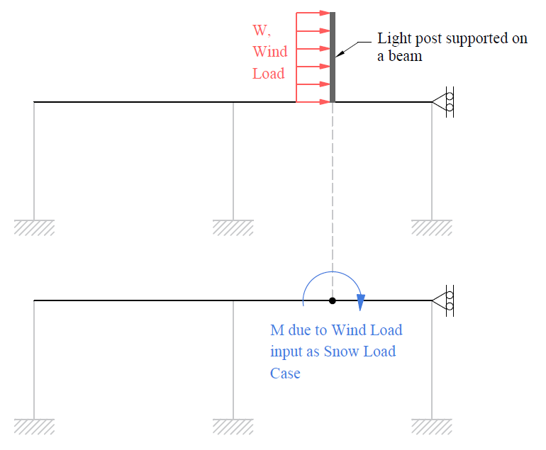
Figure 2.32 - Loads along the Span imposed by Lateral Loading
StructurePoint anticipates the inclusion of additional load cases to accommodate lateral loads being applied to the span in future releases once adequate consideration and research has been done to the effects of live load patterning and deflection calculations for lateral forces. It is anticipated that the inclusion of lateral forces will complicate greatly the procedure of live load arrangement and patterning, in addition to the added complexity of calculating sustained live loads that are an essential part of the deflection calculations specifically long term.
2.6.3. Gravity Frame Analysis under Sidesway
The spBeam program is a powerful tool for modeling one-way, multi-story, two-dimensional concrete frames, allowing users to analyze individual stories as separate frames. Each story is modeled with slab beam elements and columns above and below, employing an equivalent column concept and restraining horizontal translational degrees of freedom at the story level. However, in scenarios where unsymmetrical vertical loading, variations in support stiffness, or boundary conditions induce horizontal sidesway, the spFrame program provides a more comprehensive analysis. Unlike spBeam, spFrame accommodates the entire height of a two-dimensional frame, accurately accounting for sidesway effects on internal force magnitudes. A comparative analysis, conducted in "Comparison of Gravity Loaded Concrete Frame Models in spBeam and spFrame under Sidesway" Technical Article from StructurePoint, illustrates that while spBeam assumes sidesway restraint, spFrame considers its effects, leading to more reliable results for design under such conditions.
2.6.4. Openings in Concrete Slabs
Openings in concrete slabs significantly influence their structural behavior, particularly in terms of shear strength and load distribution. The presence of openings alters the flow of internal forces, potentially reducing the slab's capacity to resist shear and flexure while introducing stress concentrations around the perimeters of the openings. Theoretical approaches outlined in design codes such as ACI 318 and CSA A23.3 provide guidance on analyzing and designing slabs with openings, emphasizing the importance of maintaining adequate shear transfer mechanisms. The scope of these provisions includes practical design scenarios for slabs with various types and sizes of openings, ensuring that safety and functionality are preserved. The purpose of these guidelines is to enable engineers to design reinforced concrete slabs with openings that meet structural performance criteria while accommodating architectural or functional requirements, such as ductwork, piping, and access points, without compromising the slab's integrity or serviceability. More information about this topic can be found in "Shear Strength of Concrete Slabs with Openings (ACI 318)" and "Shear Strength of Concrete Slabs with Openings (CSA A23.3)" Design Examples from StructurePoint.
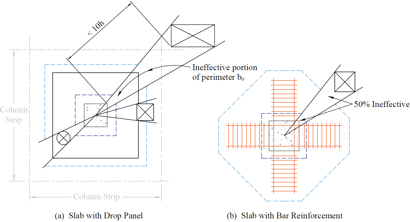
Figure 2.33 - Effect of Openings on Slabs Shear Strength
In spSlab and spBeam, defining appropriate support conditions is essential for accurate analysis and design of structural elements in a concrete floor system. By default, column-slab/beam joints are assumed to rotate freely while restricting translational displacement. The rotational stiffness of a joint is influenced by connected elements (such as slabs, beams, transverse beams, and columns) and can be adjusted using the Restraint command. Columns are typically modeled with fixed far-end boundary conditions but can be adjusted using the Column command to meet specific design needs. Engineers can specify vertical spring constants (Kz) to allow vertical displacement of joints or adjust rotational stiffness using rotational spring constants (Kry). Far-end column conditions can also be set as either fixed or pinned to match design assumptions. These options enable modeling of support conditions to achieve a closer reflection of physical conditions into the analytical models and generate more accurate results. For more details, refer to Section 2.3.2, Section 5.2.4.2, and "Deflection Observations in Girder-Supported Beams and One-way Slabs" Technical Article from StructurePoint.
Moment redistribution is a design approach applied to optimize reinforcement placement and reduce material usage. The technique involves leveraging the plastic behavior of structures, which allows for a redistribution of bending moments beyond the elastic analysis results. This redistribution reduces peak negative moments at supports, typically shifting them to positive moments in spans, enabling more efficient utilization of structural capacity. Governed by standards such as ACI 318 and CSA A23.3, moment redistribution requires sufficient ductility in plastic hinge regions to ensure stability and maintain static equilibrium. By reducing reinforcement congestion in critical areas like the support regions, this method as permissible by codes, offers advantages in material savings, labor efficiency, and improved constructability. Advanced software tools, such as spSlab and spBeam, streamline the iterative calculations involved, making the process more accessible and precise.
In some instances, while investigating existing buildings and their concrete floor systems for added forces or loads and changing occupancy, this technique has proven to eliminate the need for very costly and expensive repairs that may be very time-consuming, deeming the building uninhabitable. Used properly and with caution, this technique can also result in the ability to repurpose an existing building for long-term, durable, and safe use with new higher loads. This alone can be the main difference between increasing the carbon footprint with new construction compared with the reuse of an existing durable structure towards an additional cycle of service life and contributing to the sustainable development of the built environment.
For more details regarding moment redistribution, refer to Section 2.3.6, "Continuous Beam Design with Moment Redistribution" Design Example, and "spSlab/spBeam Moment Redistribution Applications" Technical Article from StructurePoint.
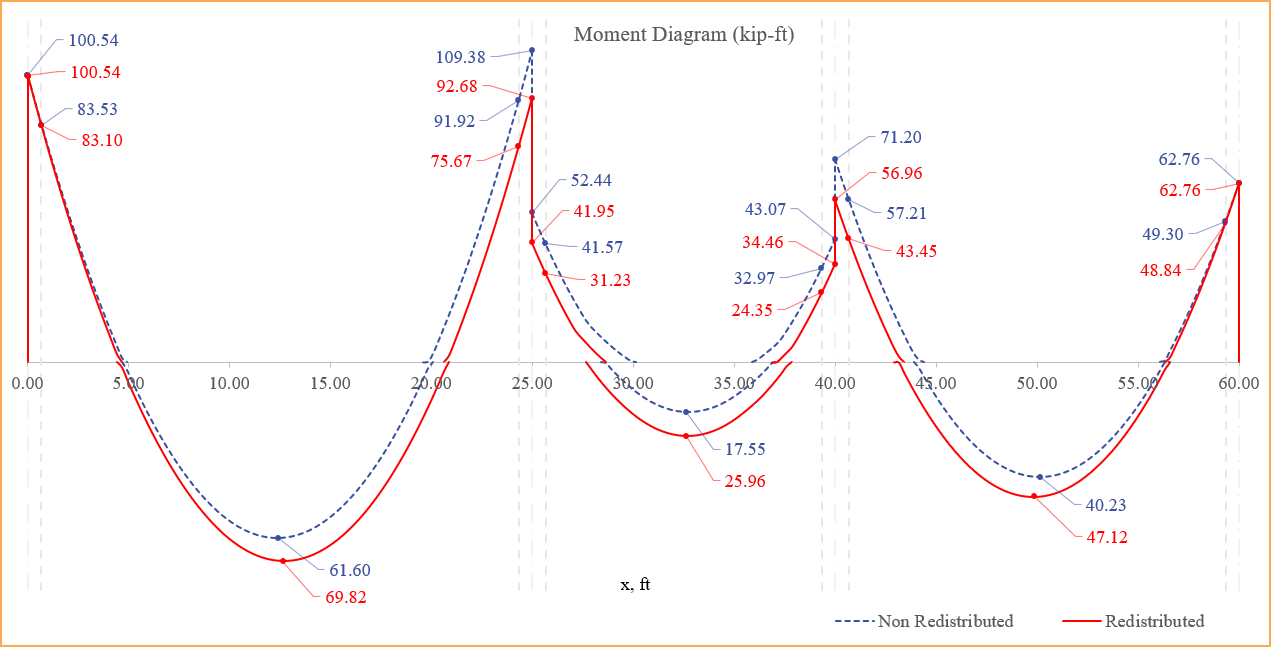
Figure 2.34 - Redistribution of Moments
2.6.7. Default Load Assignment Impact on Deflections
In spBeam and spSlab, the deflection calculations are performed by considering all assigned loading belonging to Load Cases of “Dead” and “Live” Load Type with a service load factor of 1.0 automatically. This process is followed by default by the Program regardless of the Load Cases utilized with non-zero load factors in the Load Combinations Menu for the ultimate-level design of the model.
The models generated through the Template Module incorporate Dead and Live Load assignments by default unless the load magnitude is modified to zero (0) by the user. These Load Cases with default assigned load factors of 1.0 will be utilized in deflection calculations even if they are given a zero (0) load factor in the Load Combinations Menu for project-specific reasons. Therefore, to obtain accurate deflection results, the user is advised to review all the load assignments before running the model and eliminate any unnecessary default load assignments that may have been assigned in the Templates Module. While this condition is not frequently needed in practical analysis and design applications, the software approaches the deflection calculations systematically for the traditional deflection calculations.
2.6.8. Reinforcing Bar Arrangement Impact on Deflections
In spSlab and spBeam, reinforcing bar arrangement plays an important role in accurately calculating deflections in concrete structural elements. These programs offer flexible solve options, including the activation of the compression reinforcement, which influences how reinforcing bars are considered in the calculation of the cracked moment of inertia (Icr). This feature affects deflection results significantly, especially when both continuous and discontinuous reinforcement types are present. By understanding the impact of these solve options and the associated bar arrangements, engineers can optimize structural analysis and achieve design outcomes tailored to project requirements. More information about this topic can be found in the "spSlab/spBeam Reinforcing Bar Arrangement Impact on Deflections" Technical Article from StructurePoint.
2.6.9. Design of Doubly Reinforced Beam Sections
The design of doubly reinforced beam sections incorporates both tension and compression reinforcements, allowing for enhanced ductility and strength while maintaining the section within the tension-controlled region. This approach is particularly valuable in scenarios where architectural constraints limit beam dimensions or where reducing beam weight is a priority. By adding compression reinforcement, engineers can effectively utilize higher percentages of tension reinforcement without exceeding strain limits, thereby achieving the required moment capacity efficiently. This design methodology aligns with the principles outlined in ACI 318 and CSA A23.3 codes, ensuring structural performance and safety. The process includes selecting an appropriate tension reinforcement ratio, integrating compression reinforcement to enhance ductility, and verifying section strength against design requirements. For more details regarding doubly reinforced beam design, refer to "Doubly Reinforced Concrete Beam Design" Design Example from StructurePoint.
2.6.10. Waffle Slabs Analysis & Design Approach
A waffle slab, also known as a two-way ribbed slab, is a structural system designed for applications requiring long spans and the ability to carry heavy loads. Its unique geometry, consisting of ribs in two directions, provides an efficient and economical solution for floors and roofs. The Equivalent Frame Method (EFM) is commonly used to analyze and design waffle slabs, simplifying the complexities of their ribbed structure while ensuring compliance with design standards. For a detailed explanation of the analysis and design methodology, including considerations for rib dimensions, slab thickness, drop panels (drop heads), shear analysis, and deflection calculations, refer to Section 2.2.1.4 and "Two-Way Joist (Waffle) Slab Design Approach and Methodology" Technical Article from StructurePoint.
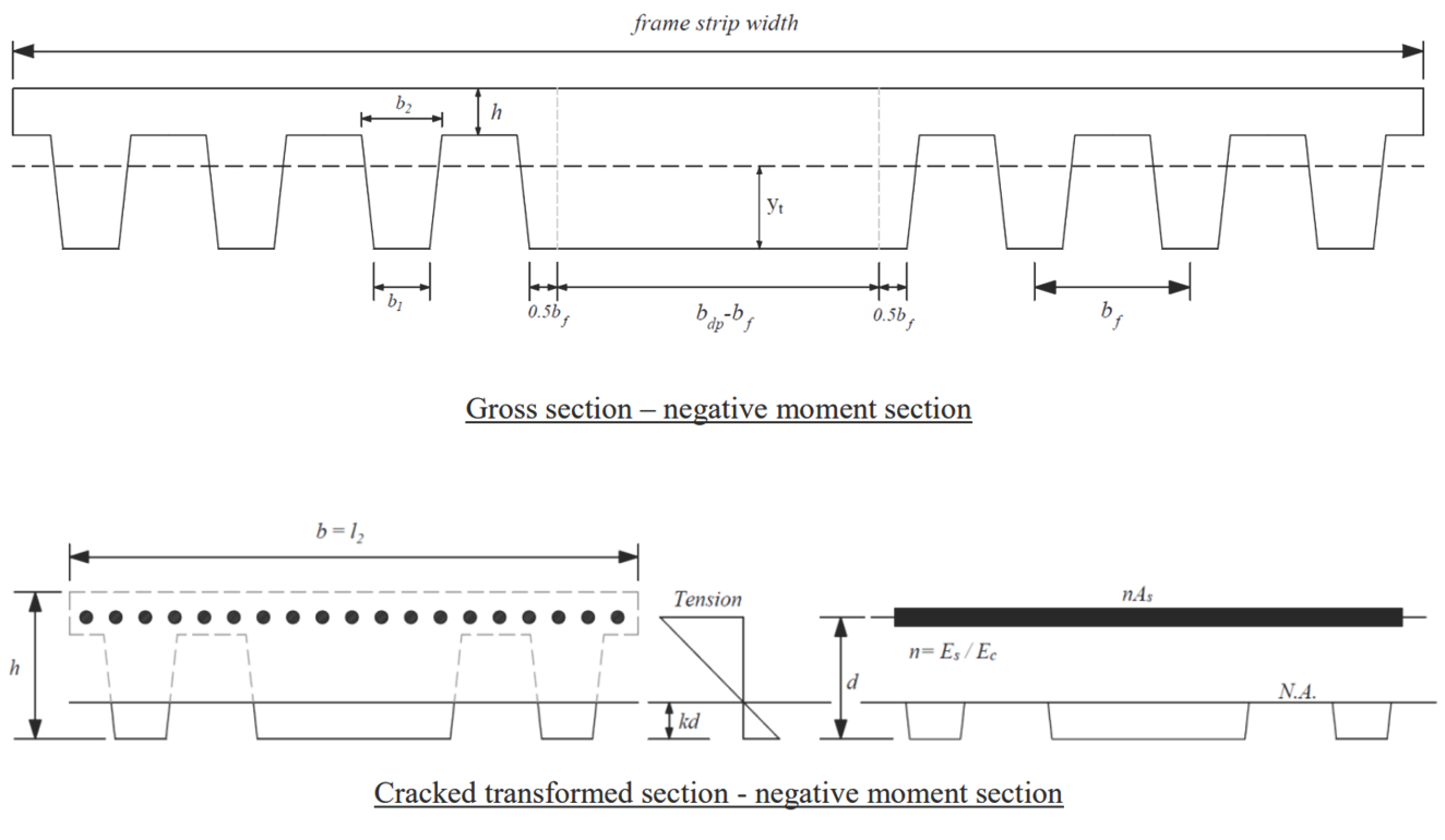
Figure 2.35 - Immediate Deflection Considerations for Negative Moment Sections
2.6.11. Material Quantities
The program computes concrete and reinforcing steel quantities. The quantity of concrete is based on an average of the slab, drop, and beam sizes. The total quantity of reinforcing steel computed by the program corresponds to the actual bar sizes and lengths required by design. No allowance is made for bar hooks, anchorage embedment, and so forth. It should be noted that the quantity of reinforcement printed by the program pertains to bending in one direction only. In practice, the total amount of reinforcement for the structure should also include the quantities obtained for the appropriate transverse equivalent frames.
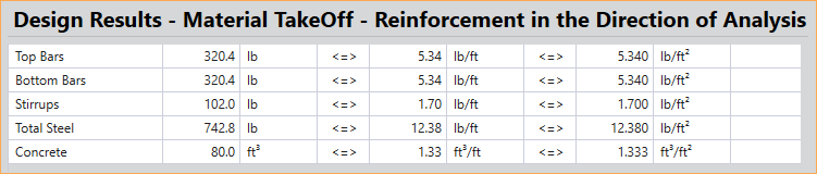
Figure 2.36 - spSlab Material Takeoff Table