Video Tutorials
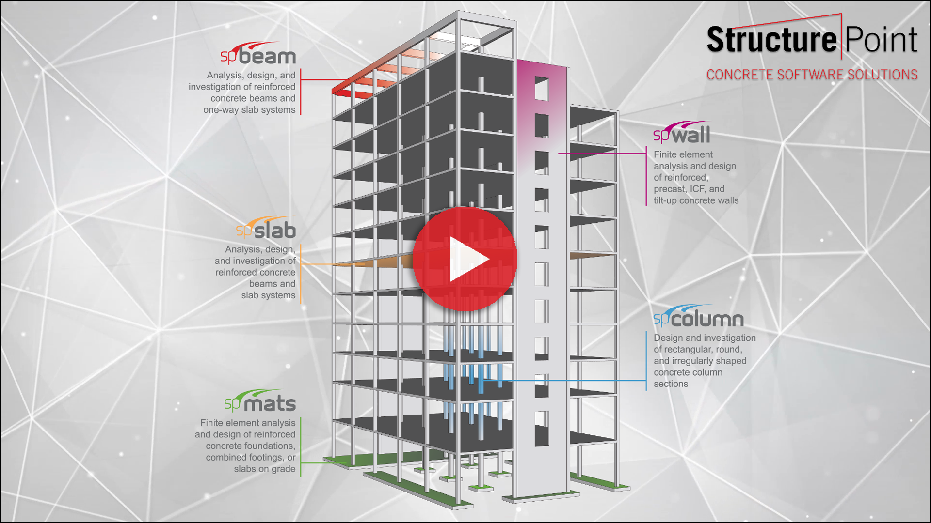
StructurePoint Software Suite are utilized by engineers worldwide to provide structural solutions for wide range of concrete structures. These Software Programs are equipped with the latest American and Canadian concrete codes. The StructurePoint Software Suite is comprised of six programs for analysis, design and investigation of structural members such as reinforced concrete beams, columns, mats, walls, slab systems, and analysis of structural frame systems.
The StructurePoint software is widely used for the analysis, design, and investigation of reinforced concrete buildings of various size and height. Applications cover gravity and lateral load resisting systems along with required foundations. Each StructurePoint software module is also used by engineers for the analysis, design and investigation of a wide variety of special concrete structures and individual concrete elements.
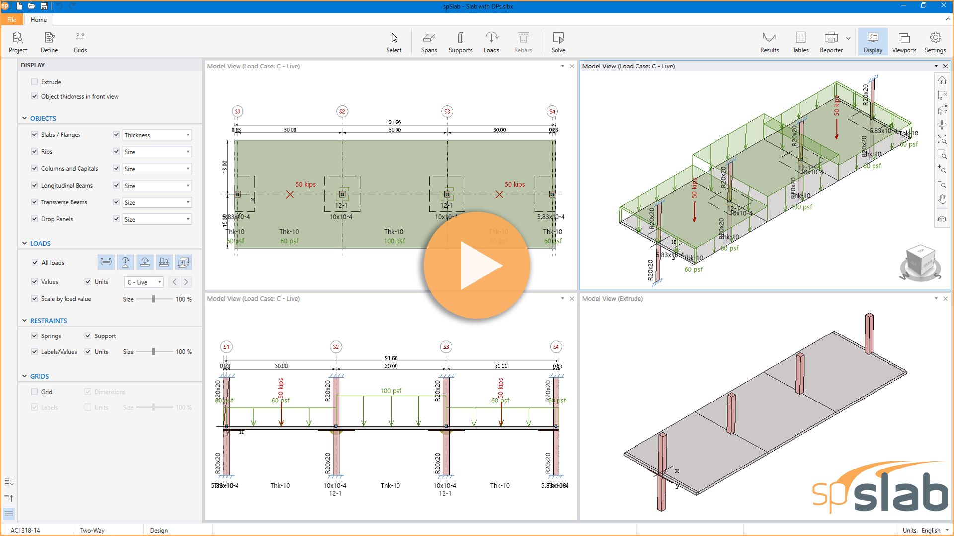
The most significant upgrade to spSlab since its inception features a pioneering interface for intuitive modeling, fast results, logical reporting, and sophisticated tools all cleverly integrated into a simple and friendly workspace.
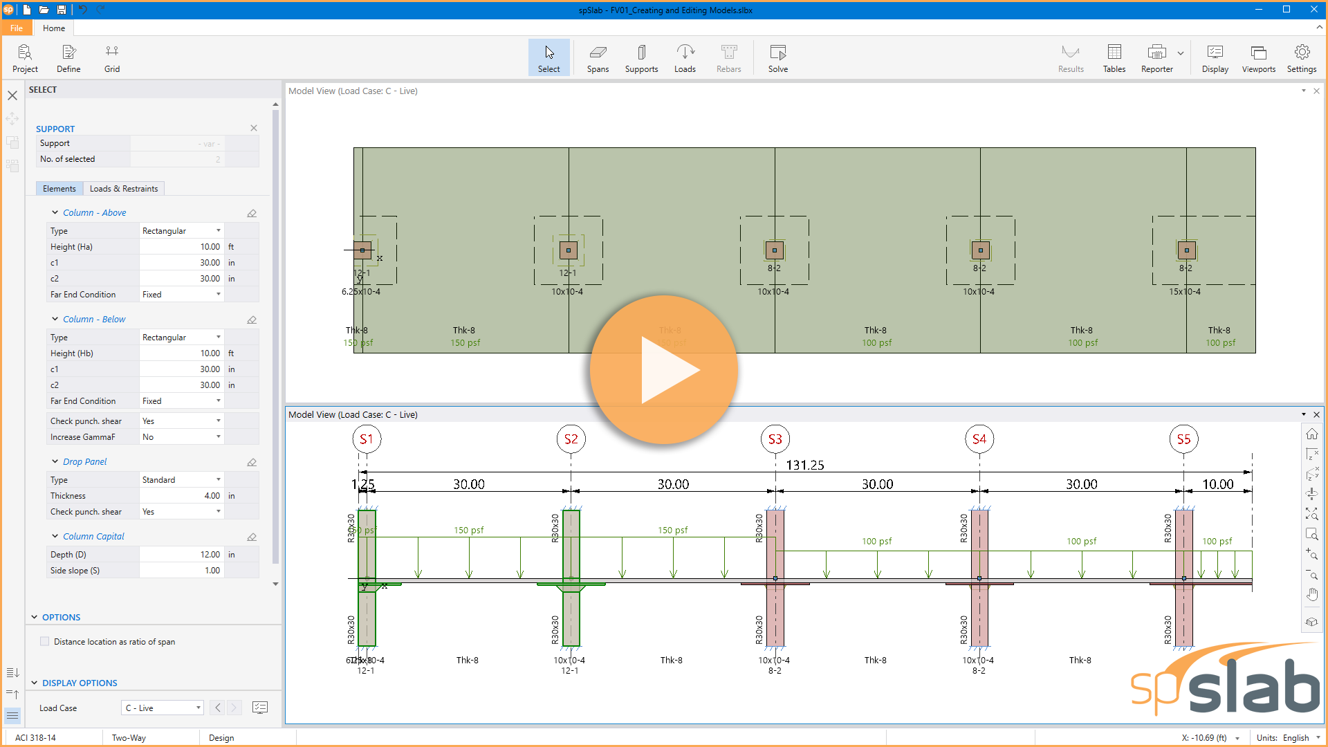
Learn how to create and edit models, define and assign span elements, support elements, and loads, and navigate existing models using spSlab's quick and simple tools. These tools support a wide range of slab system designs, including two-way flat plates, flat slabs with drop panels, slabs with beams, waffle slabs, and slabs with slab bands.
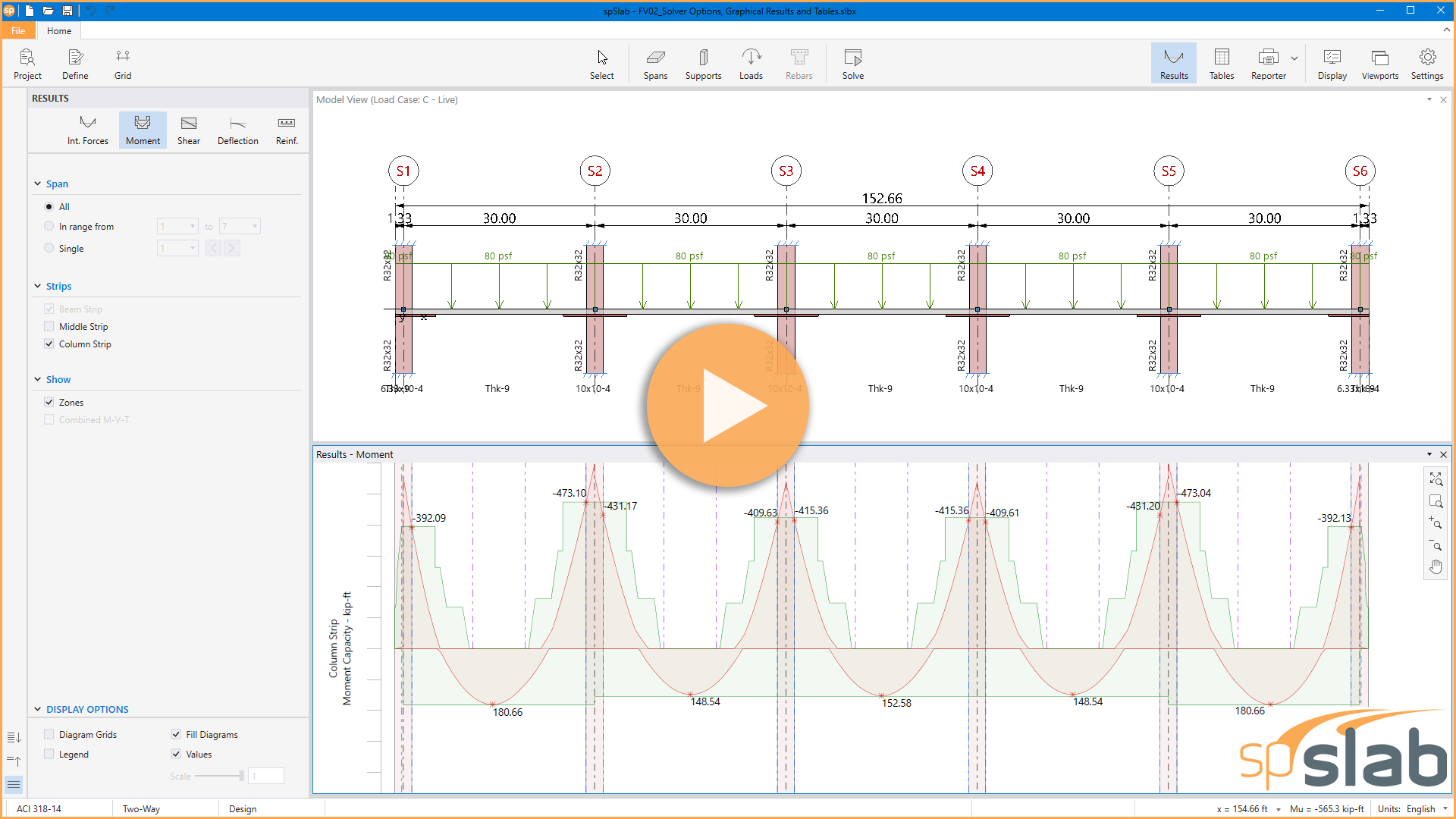
Tutorial video to demonstrate the new spSlab solve options, output diagrams and tables.
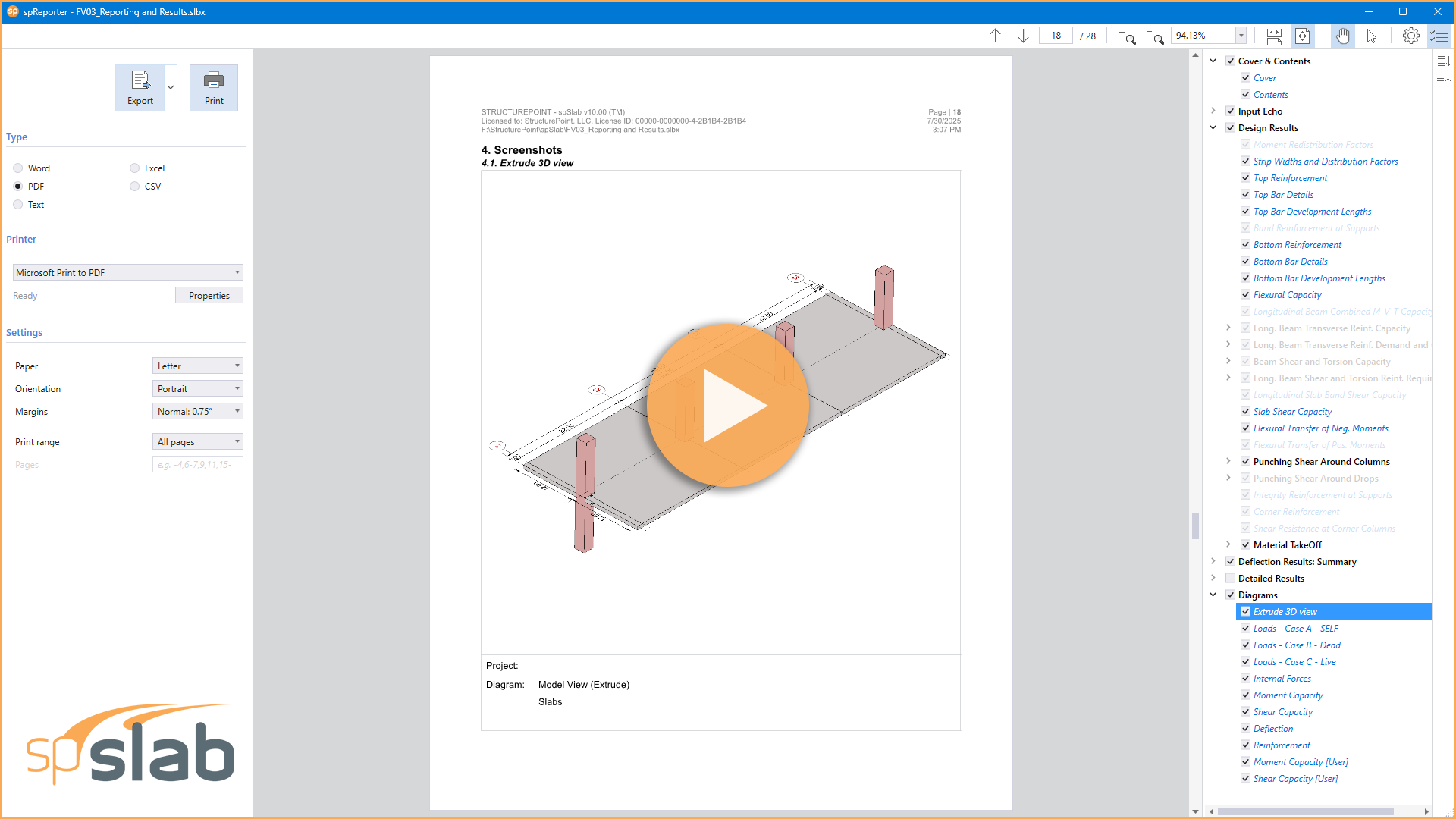
Tutorial video shows how to report, print, and export results using spSlab new interface.
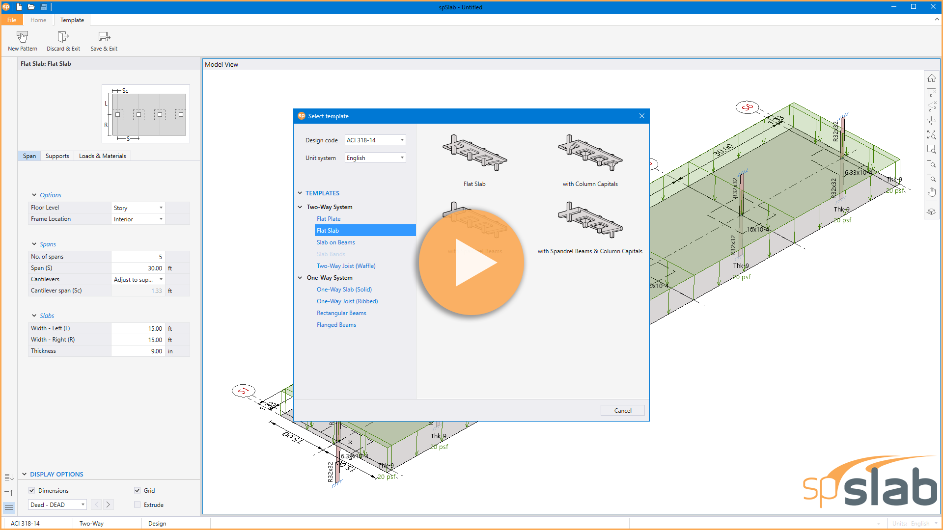
Tutorial video shows a brief description of the new spSlab templates module.
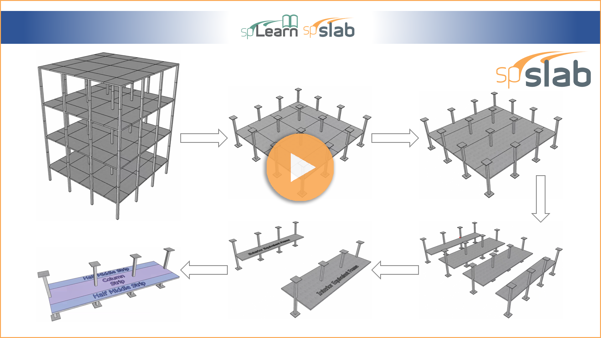
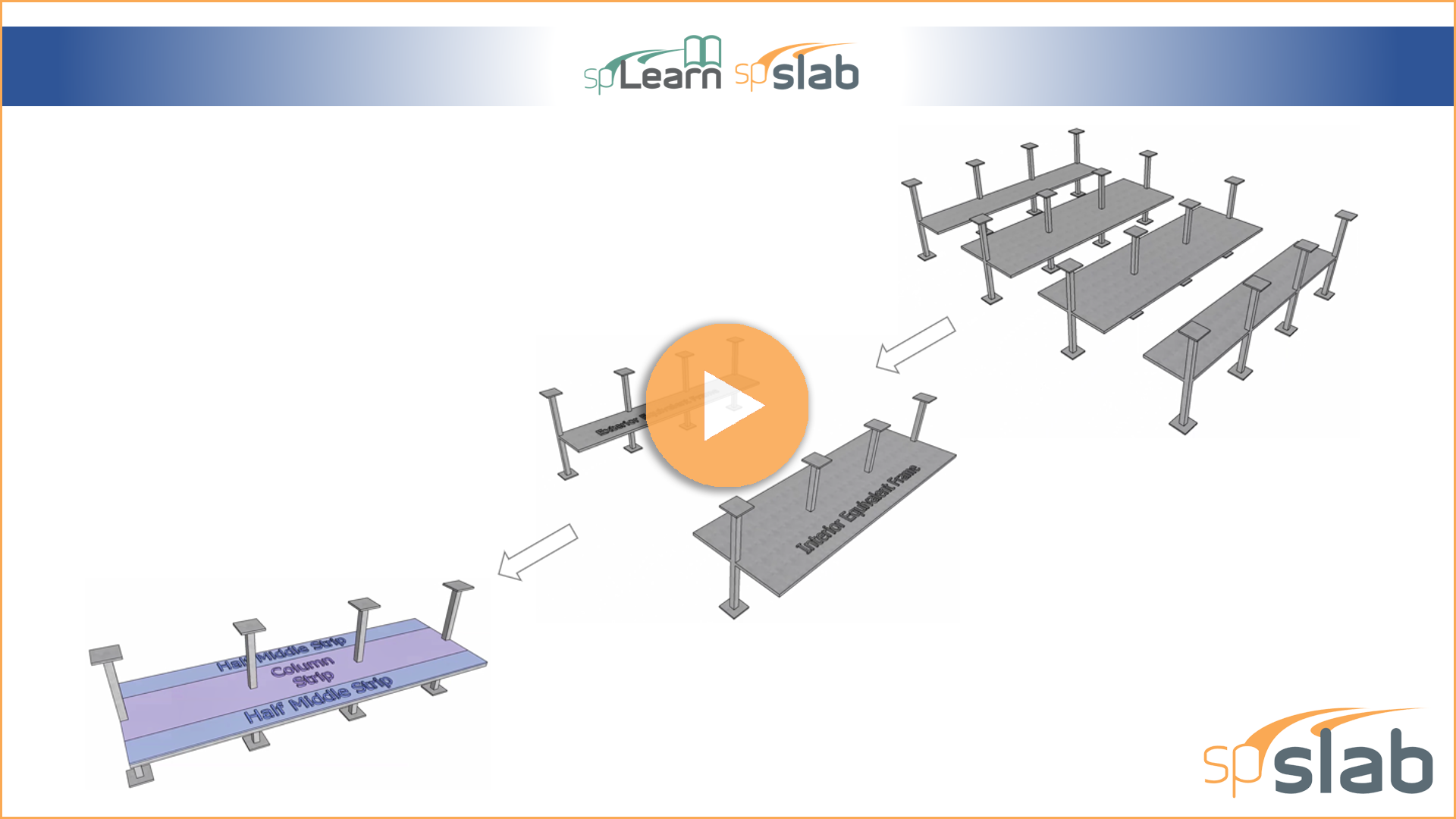
A detailed illustration of the procedures required to understand and utilize the Equivalent Frame Method (EFM) in the analysis and design of two-way concrete floor slab systems. A description of design, column, and middle strips is included.
An animated introduction to the basics of the Equivalent Frame Method (EFM) for the analysis and design of two-way concrete floor slab systems.
A detailed illustration of the two-way floor systems that can be analyzed and designed by spSlab including an introduction of the Equivalent Frame Method (EFM).
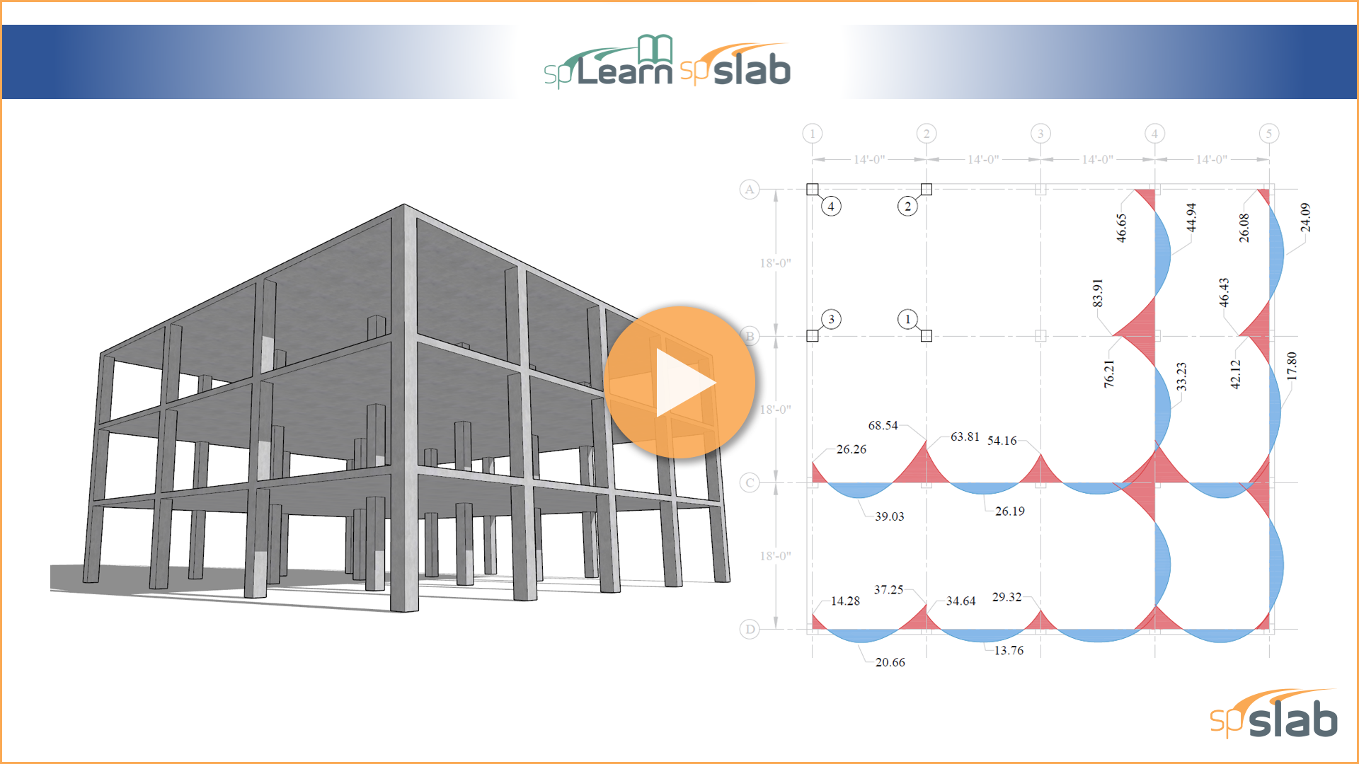
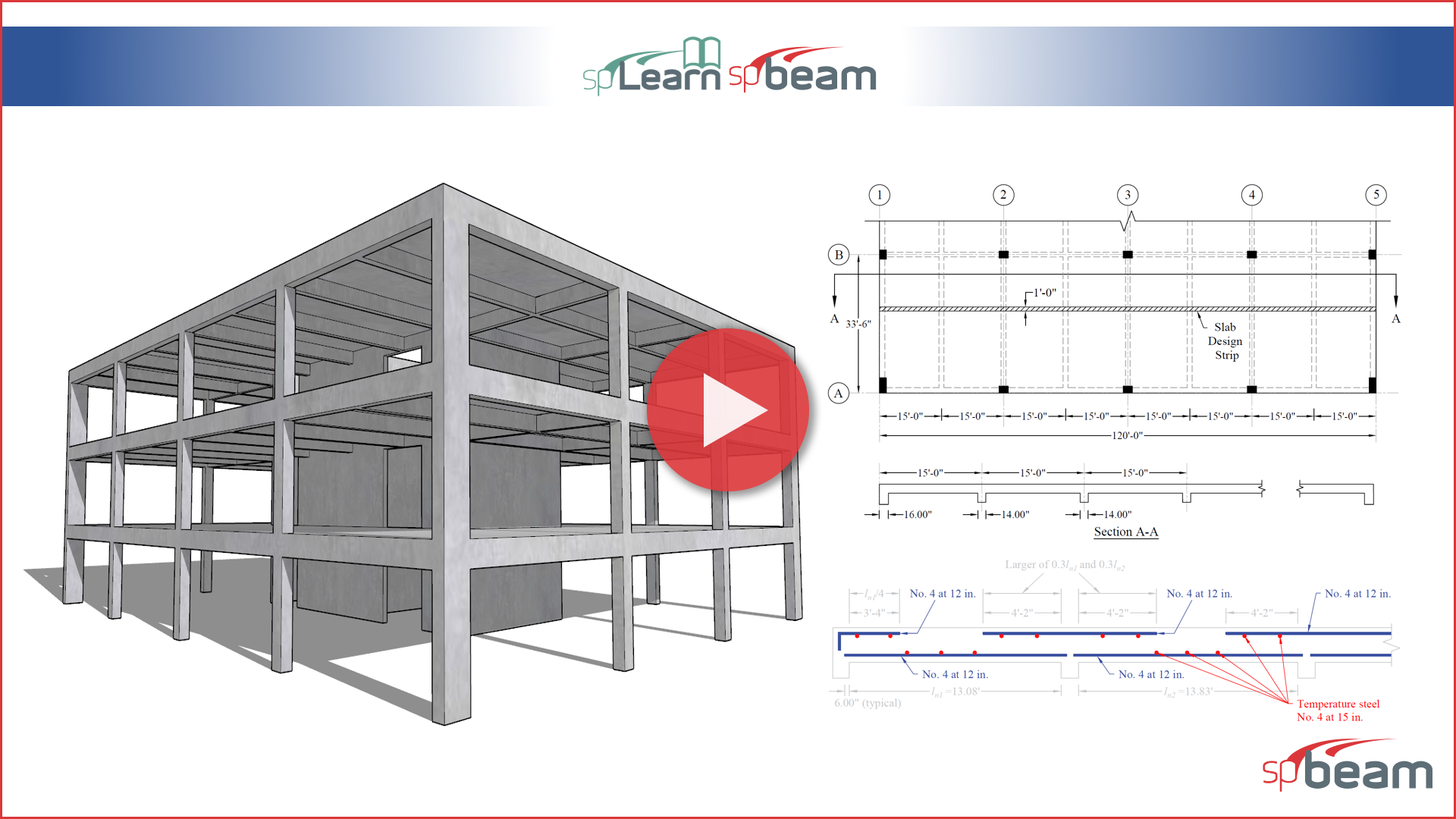
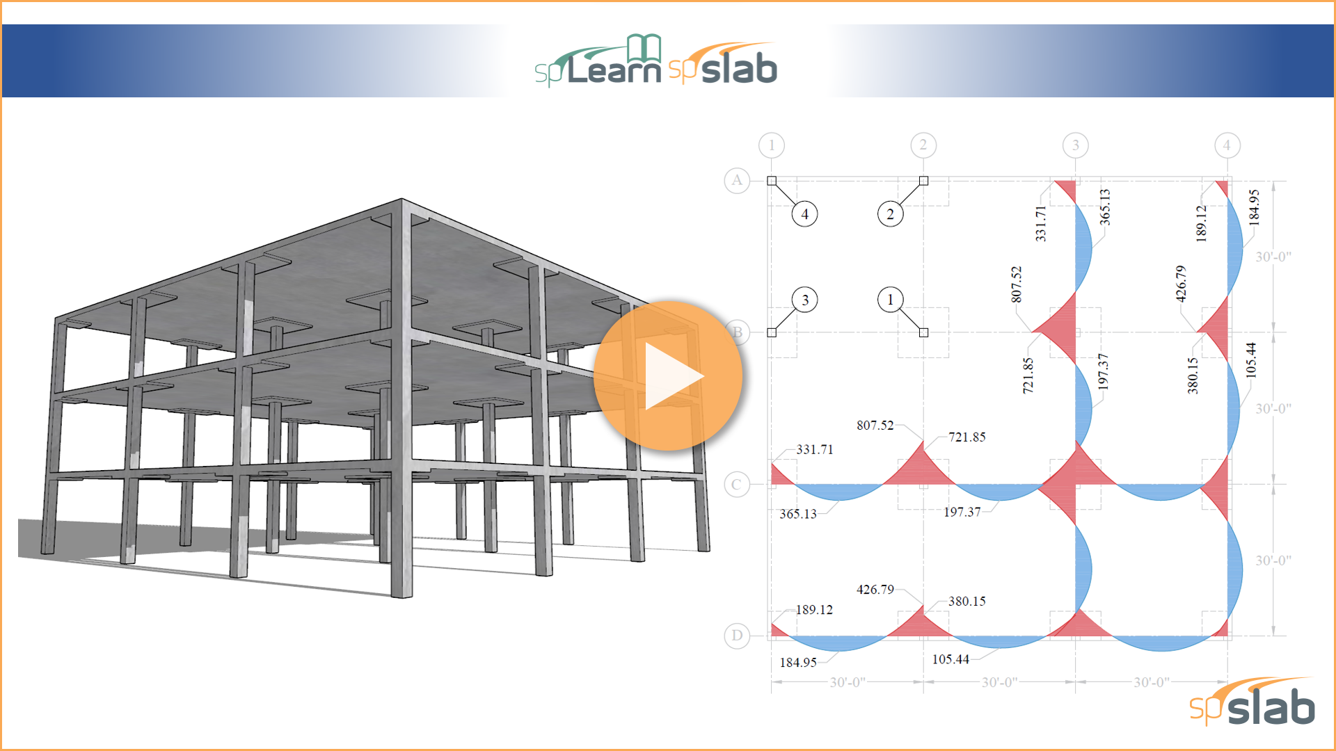
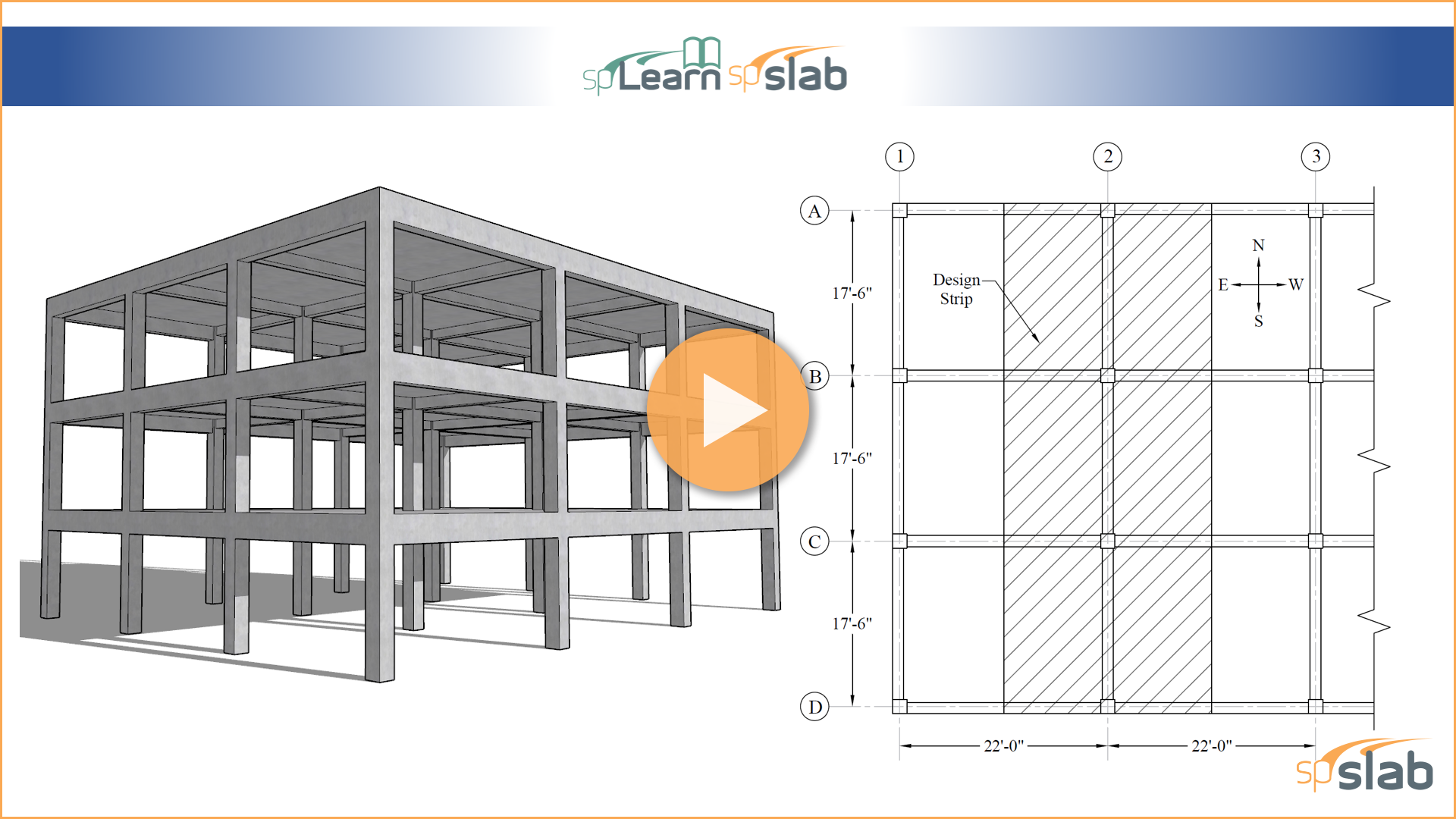
This video illustrates the analysis and design of a two-way flat plate concrete floor system. The demonstration focuses on the use of the American code (ACI 318-14), and compares the hand solution using the Equivalent Frame Method (EFM) with the analysis and design results obtained from spSlab v5.50 engineering software program by StructurePoint.
The most significant upgrade to spBeam since its inception features a pioneering interface for intuitive modeling, fast results, logical reporting, and sophisticated tools all cleverly integrated into a simple and friendly workspace.
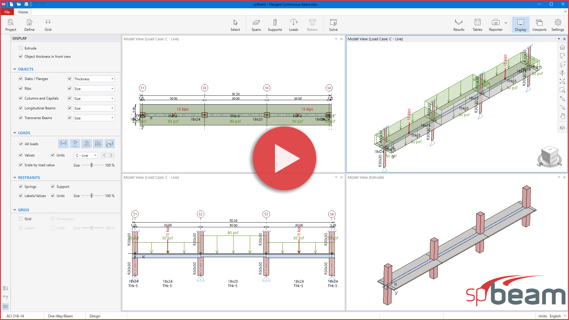
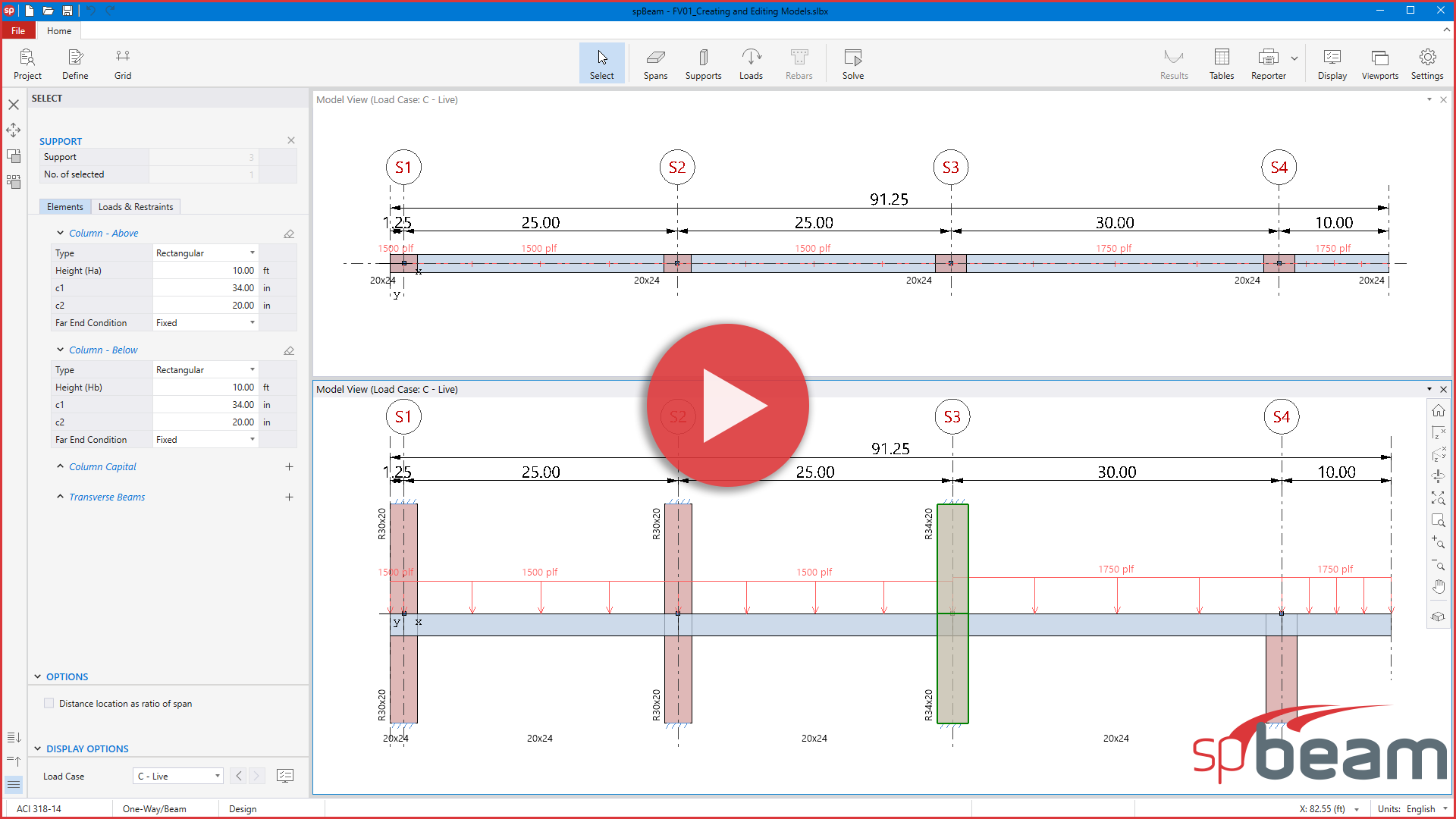
Learn how to create and edit models, define and assign span elements, support elements, and loads, and navigate existing models using spBeam's quick and simple tools. These tools support a wide range of one-way and beam systems designs, including one-way (solid) slabs, one-way joist (ribbed) slabs, rectangular and flanged continuous beams.
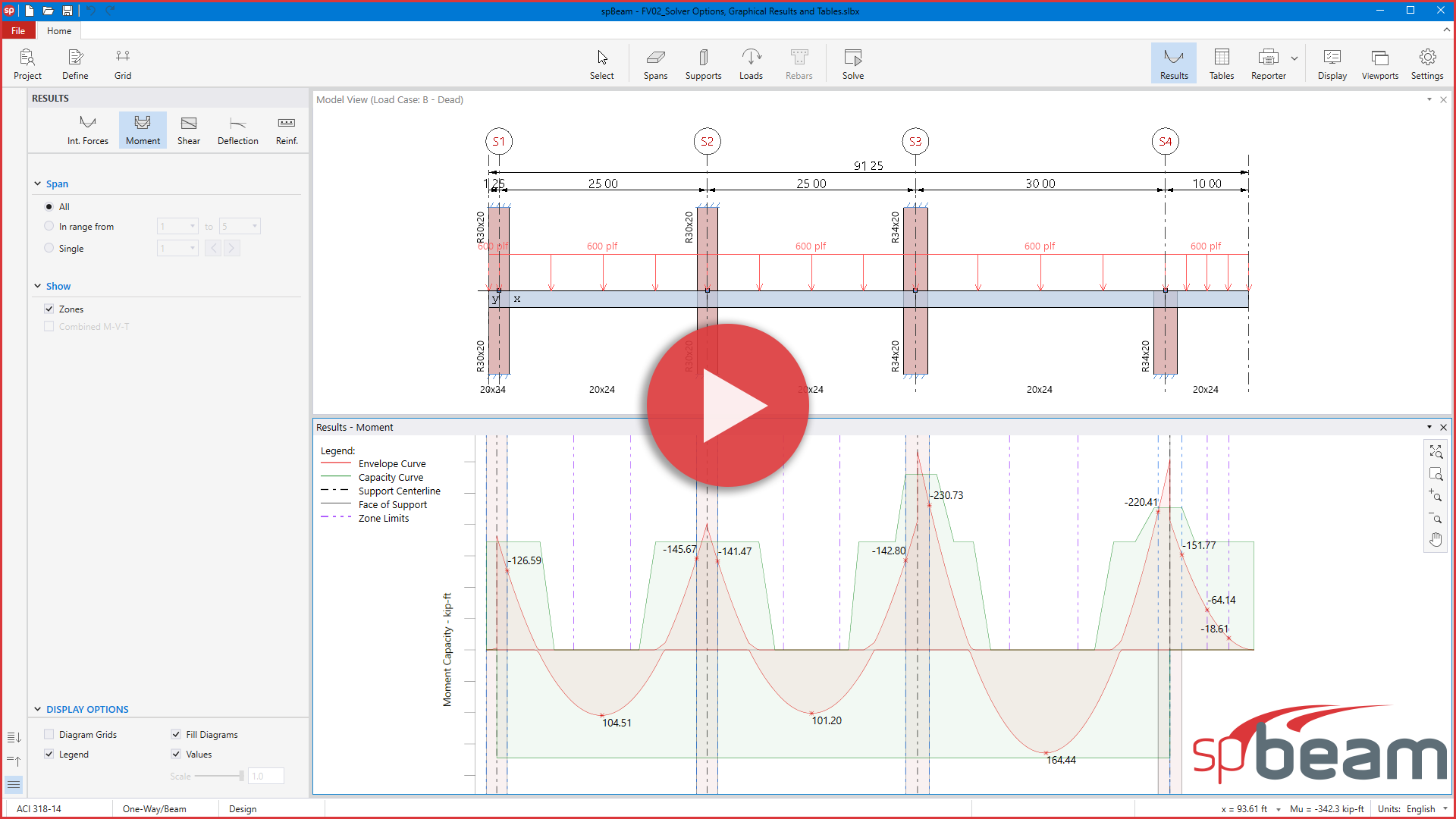
Tutorial video to demonstrate the new spBeam solve options, output diagrams and tables.
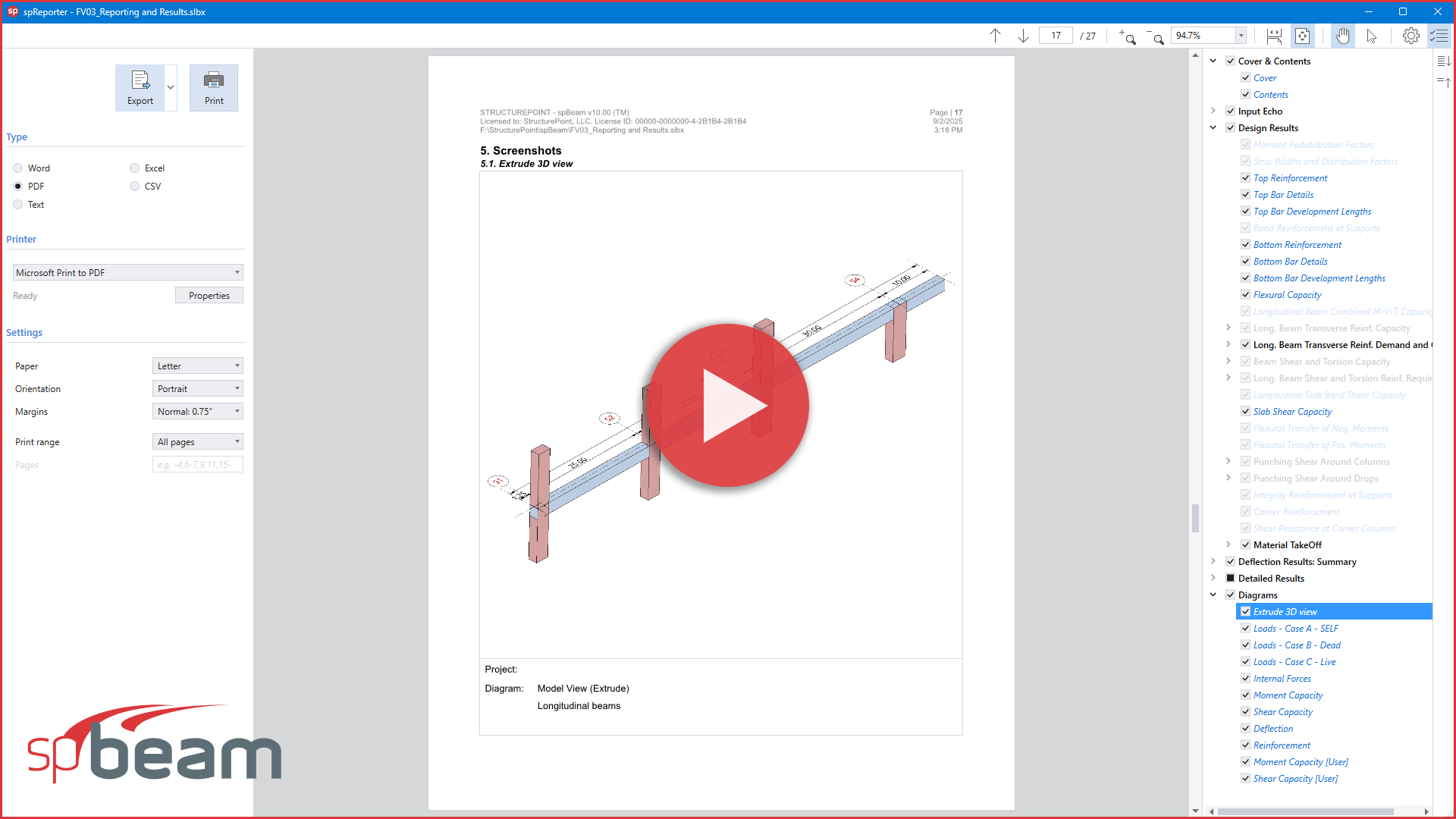
Tutorial video shows how to report, print, and export results using spBeam new interface.
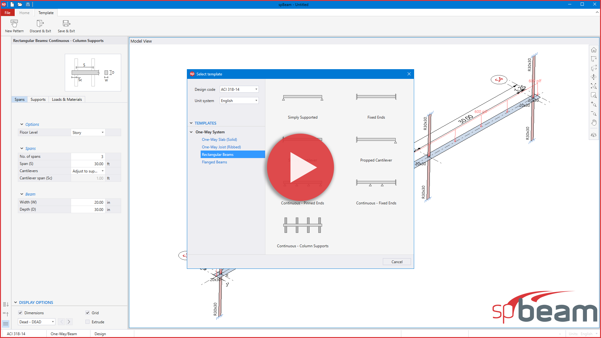
Tutorial video shows a brief description of the new spBeam templates module.
An animated review of commonly encountered boundary conditions for the analysis and design of continuous beams and one-way slab systems, and how to properly model them in reinforced concrete buildings.
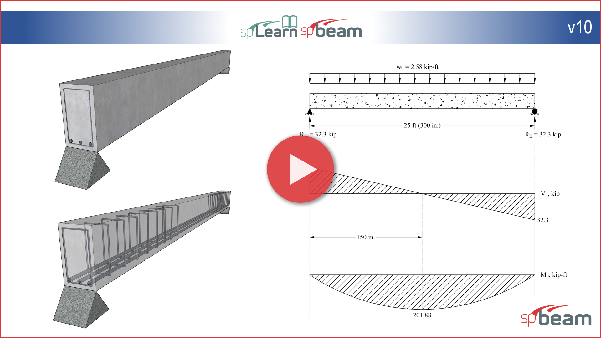
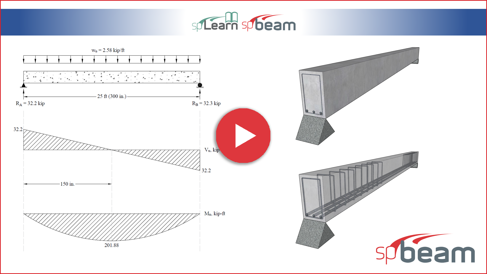
This video illustrates how to model a rectangular simply supported reinforced concrete beam using the spBeam v10.00 engineering software program by StructurePoint. The analysis and design focus on the use of the American code (ACI 318-14), and the results obtained from the program are compared with a hand solution to validate accuracy.
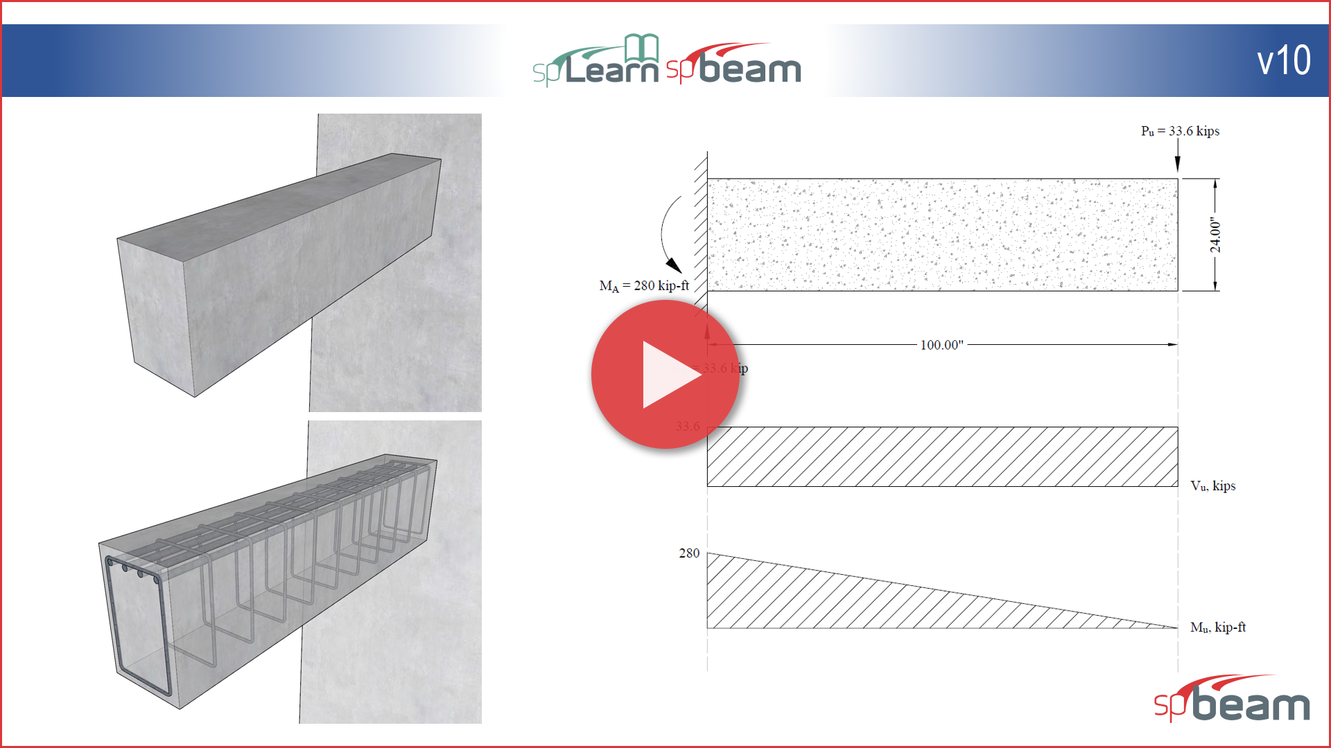
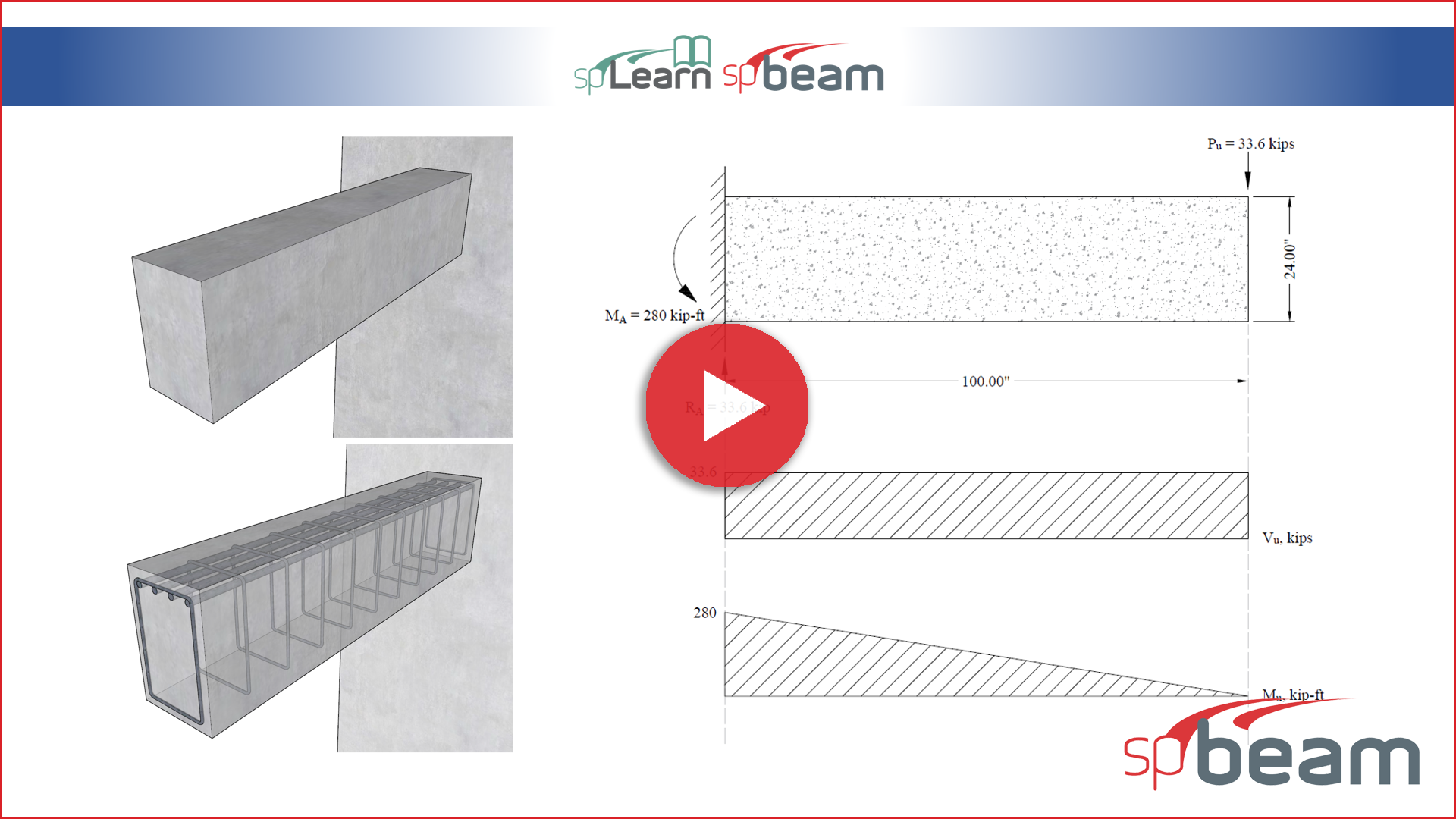
This video illustrates how to model a rectangular reinforced concrete cantilever beam using the spBeam v10.00 engineering software program by StructurePoint. The analysis and design focus on the use of the American code (ACI 318-14), and the results obtained from the program are compared with a hand solution to validate accuracy.
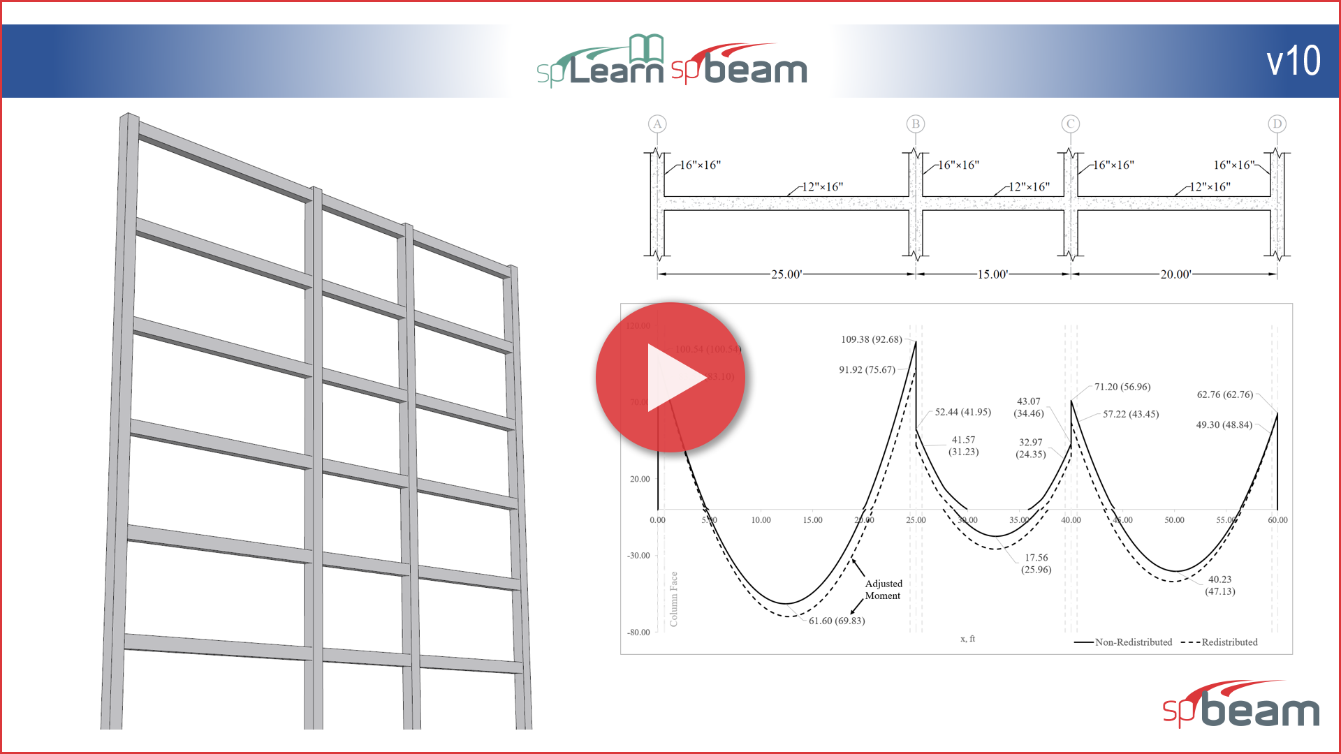
This video illustrates how to model a continuous beam with moment redistribution using the spBeam v10.00 engineering software program by StructurePoint. The analysis and design focus on the use of the American code (ACI 318-14), and the results obtained from the program are compared with a hand solution to validate accuracy.
This video demonstrates the analysis and design of a rectangular simply supported reinforced concrete beam using ACI 318-14 provisions. Steps of the structural analysis, flexural design, shear design, and deflection checks are presented using typical hand calculations and using the spBeam engineering software program by StructurePoint.
This example demonstrates the analysis and design of a rectangular reinforced concrete cantilever beam using ACI 318-14 provisions. Steps of the structural analysis, flexural design, shear design, and deflection checks are presented using typical hand calculations and using the spBeam engineering software program by StructurePoint.
This video illustrates the analysis and design of a one-way slab concrete floor system. The demonstration focuses on the use of the American code (ACI 318-14) and compares the hand solution with the analysis and design results obtained from spBeam v5.50 engineering software program by StructurePoint.
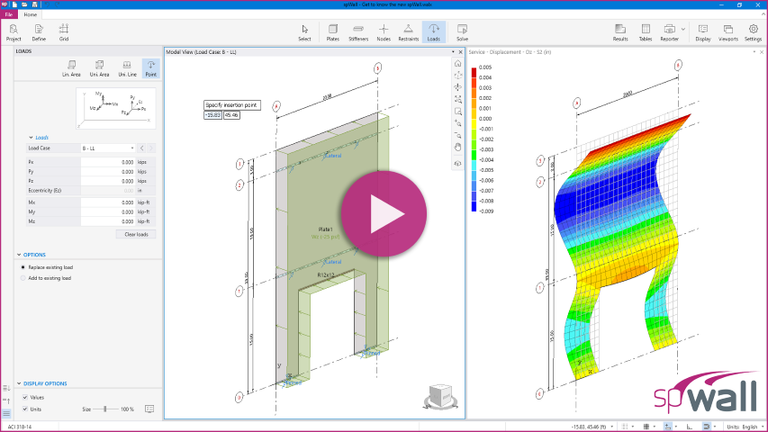
The most significant upgrade to spWall since its inception features a pioneering interface for intuitive modeling, fast results, logical reporting, and sophisticated tools all cleverly integrated into a simple and friendly workspace.
Learn how to create and edit models, define and assign restraints and loads, and navigate existing models using spWall’s quick and simple tools for building shear walls, bearing walls, precast walls, tilt-up walls, tank walls, retaining walls, and deep beams.
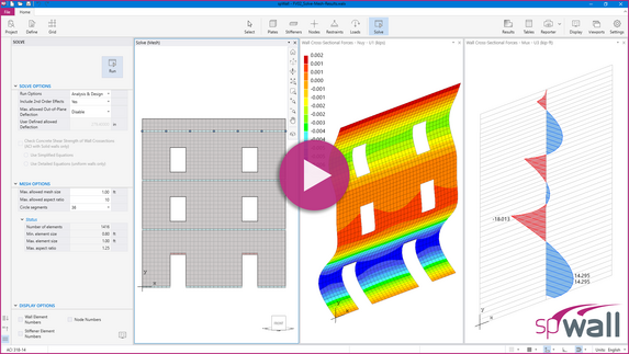
Tutorial video to demonstrate the new spWall solve options, Mesh optimization, output contours and tables.
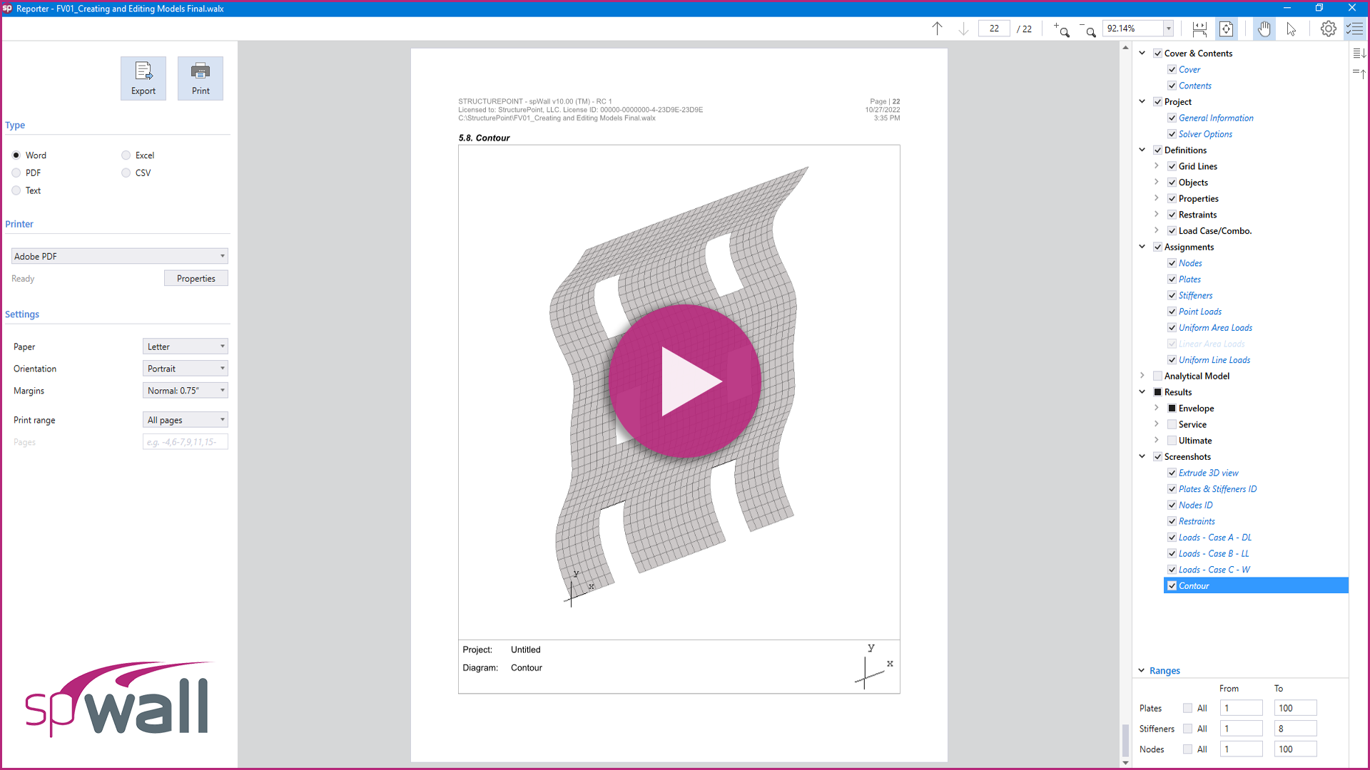
Tutorial video shows how to report and print results using spWall new interface, and how to import/export inputs and outputs.
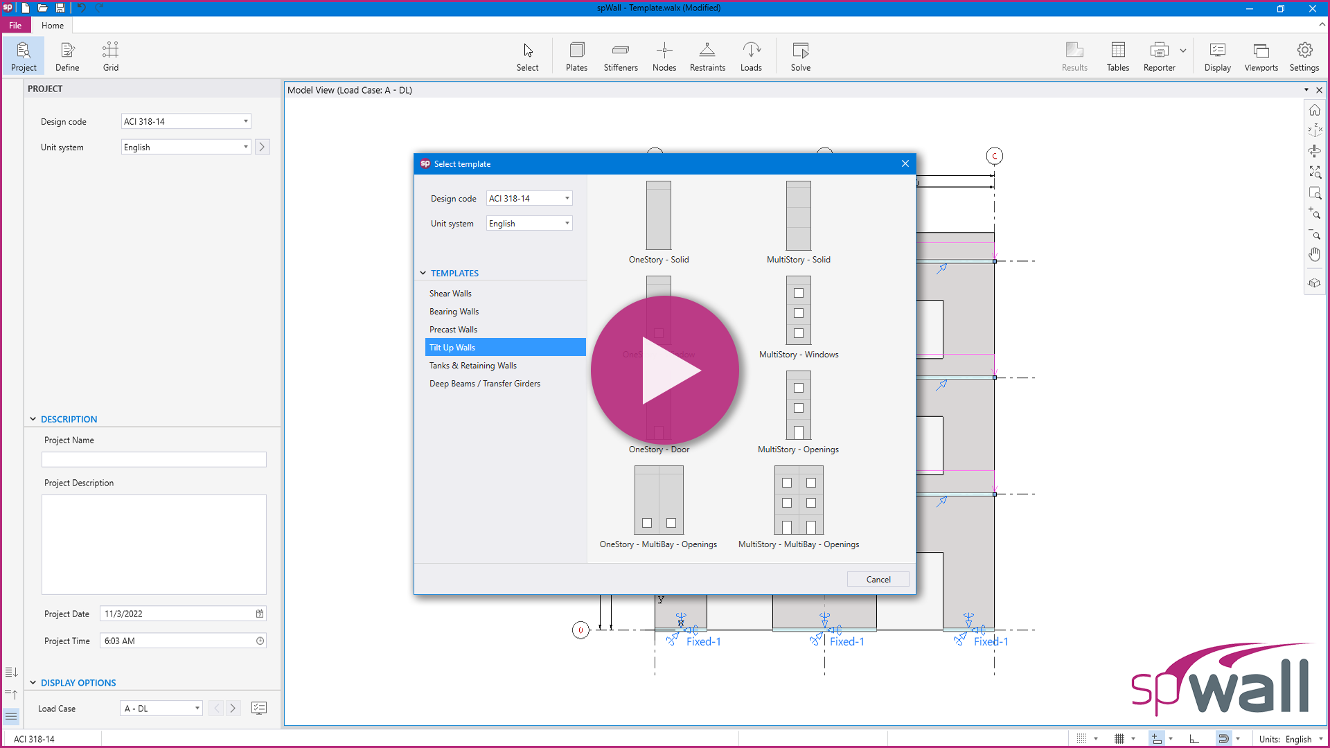
Tutorial video shows a brief description of the new spWall templates module.
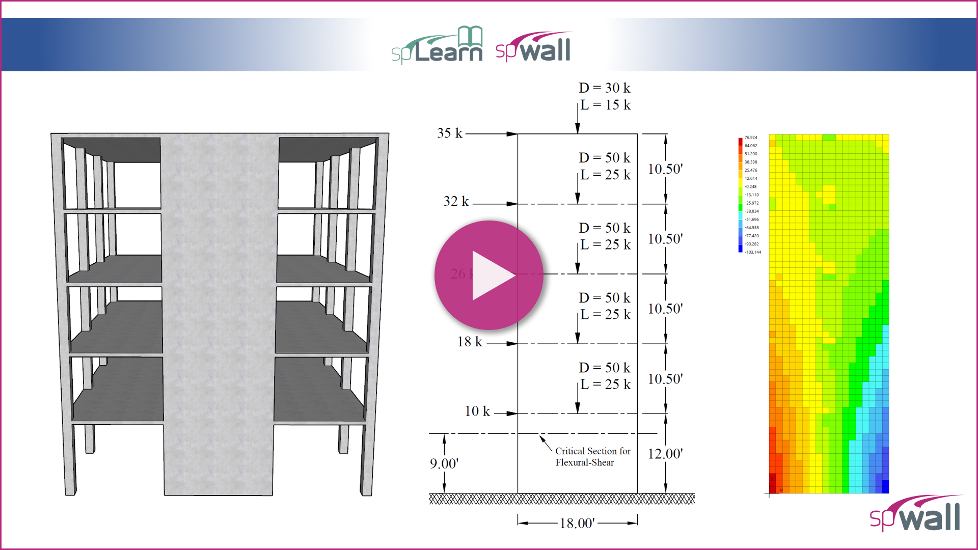
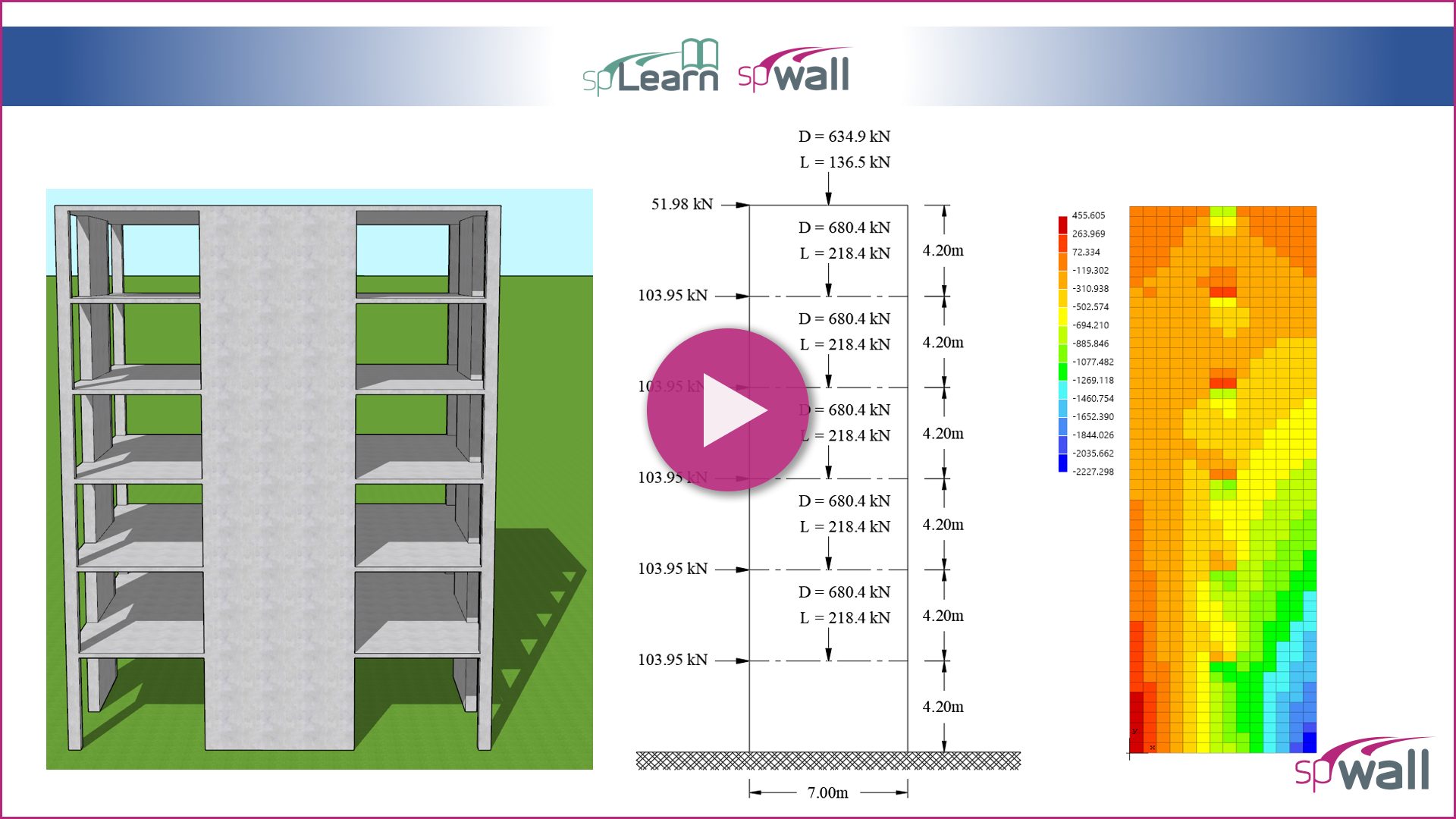
This video provides an in-depth analysis and design of reinforced concrete shear walls, which are crucial for resisting lateral loads caused by wind and seismic forces. The demonstration focuses on the use of the American code (ACI 318-14) and compares the hand solution with the analysis and design results obtained from spWall v10 engineering software program by StructurePoint.
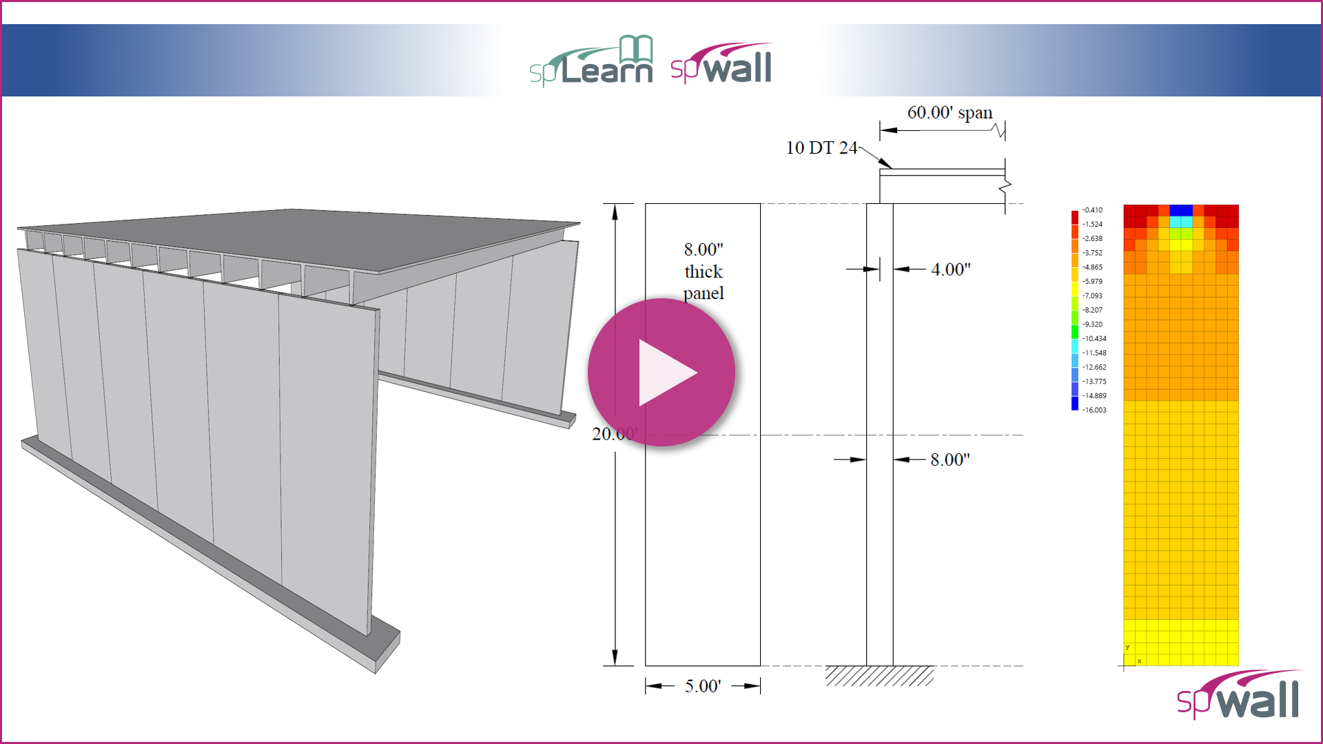
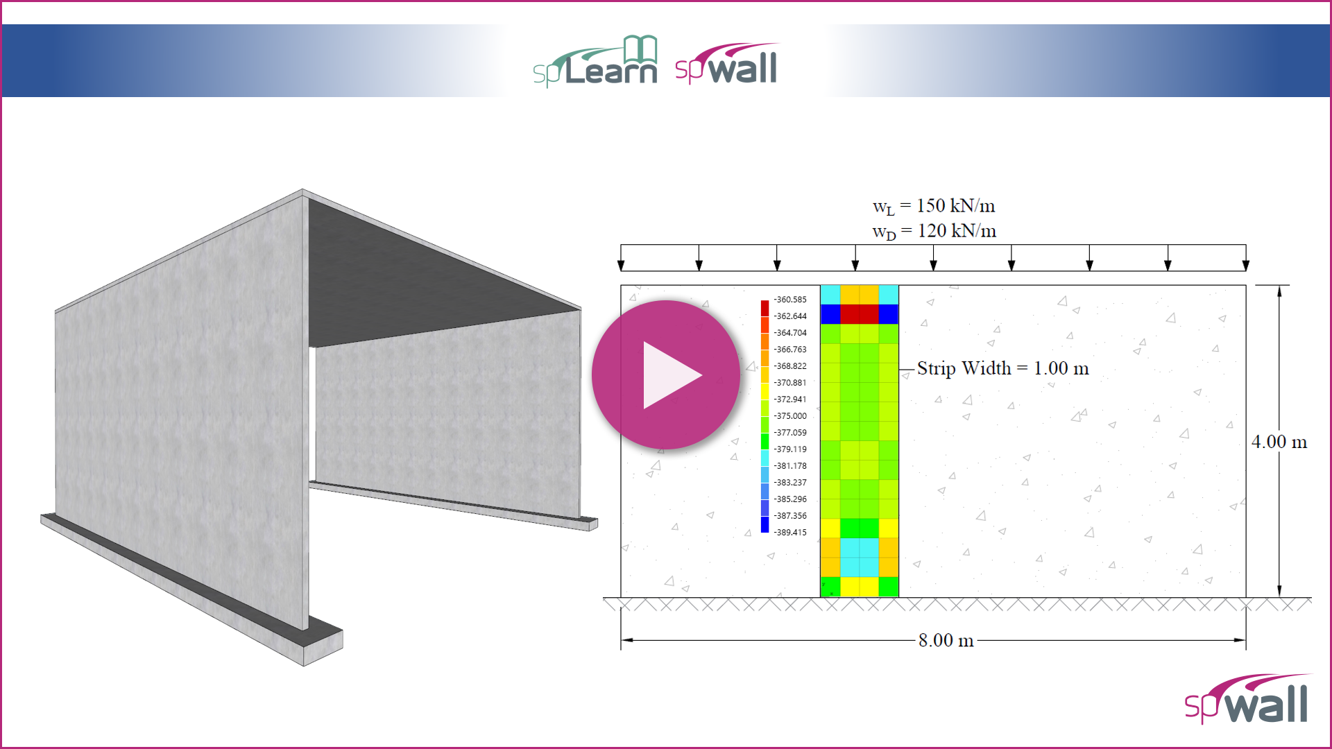
This video illustrates the analysis and design of precast reinforced concrete bearing wall panel in a single-story building based on the provisions of the American code (ACI 318-14). Alternative Method for Out-of-Plane Slender Wall Analysis in ACI 318-14 is used to demonstrate hand calculation procedures and compare with finite element analysis results from spWall v10 engineering software program from StructurePoint.
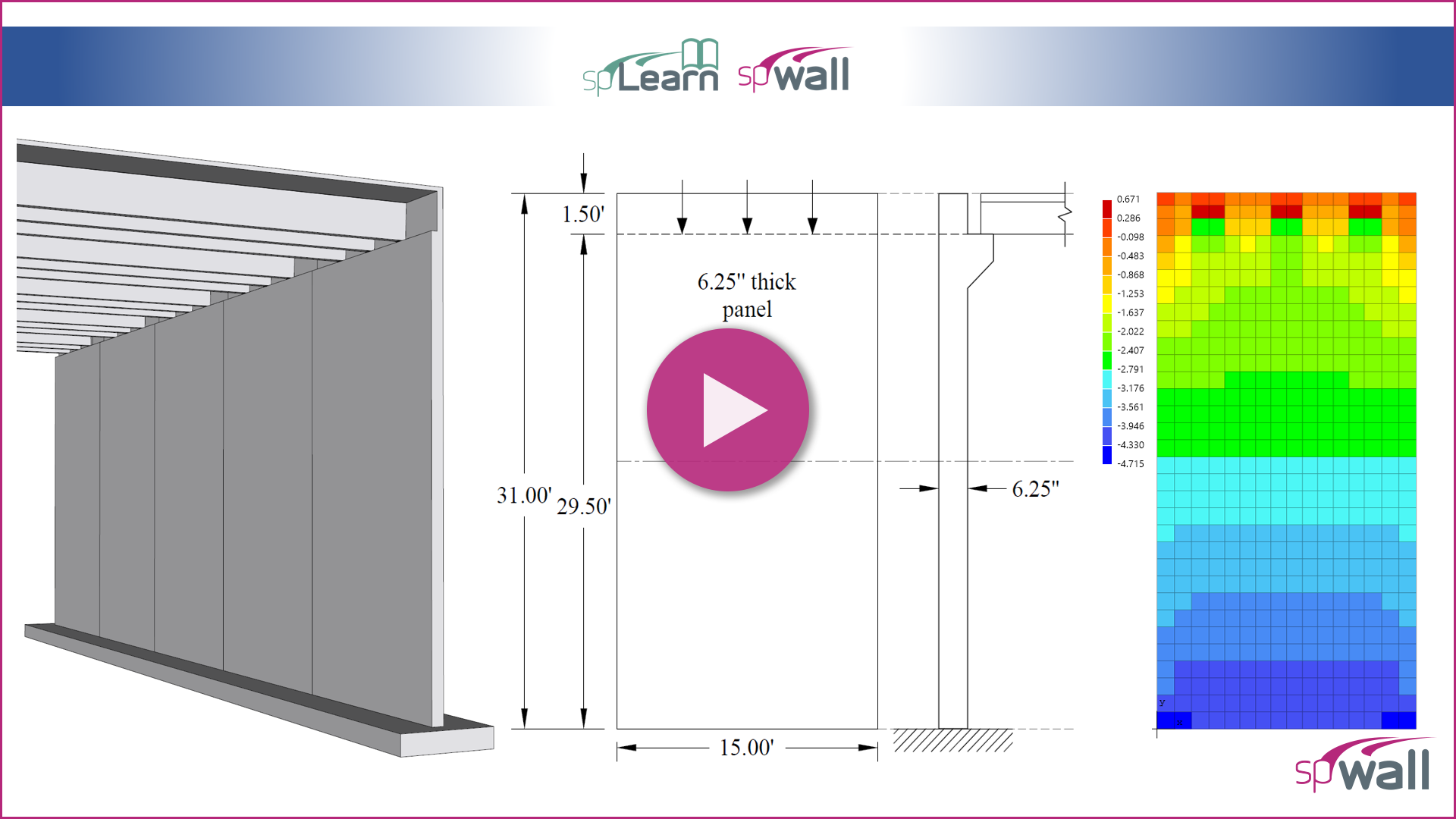
This video illustrates the analysis and design of precast reinforced concrete tilt-up wall panel in a single-story building. The demonstration focuses on the use of the American code (ACI 318-14) and the comprehensive procedure provided by ACI 551, and compares the hand solution with the analysis and design results obtained from spWall v10 engineering software program by StructurePoint.
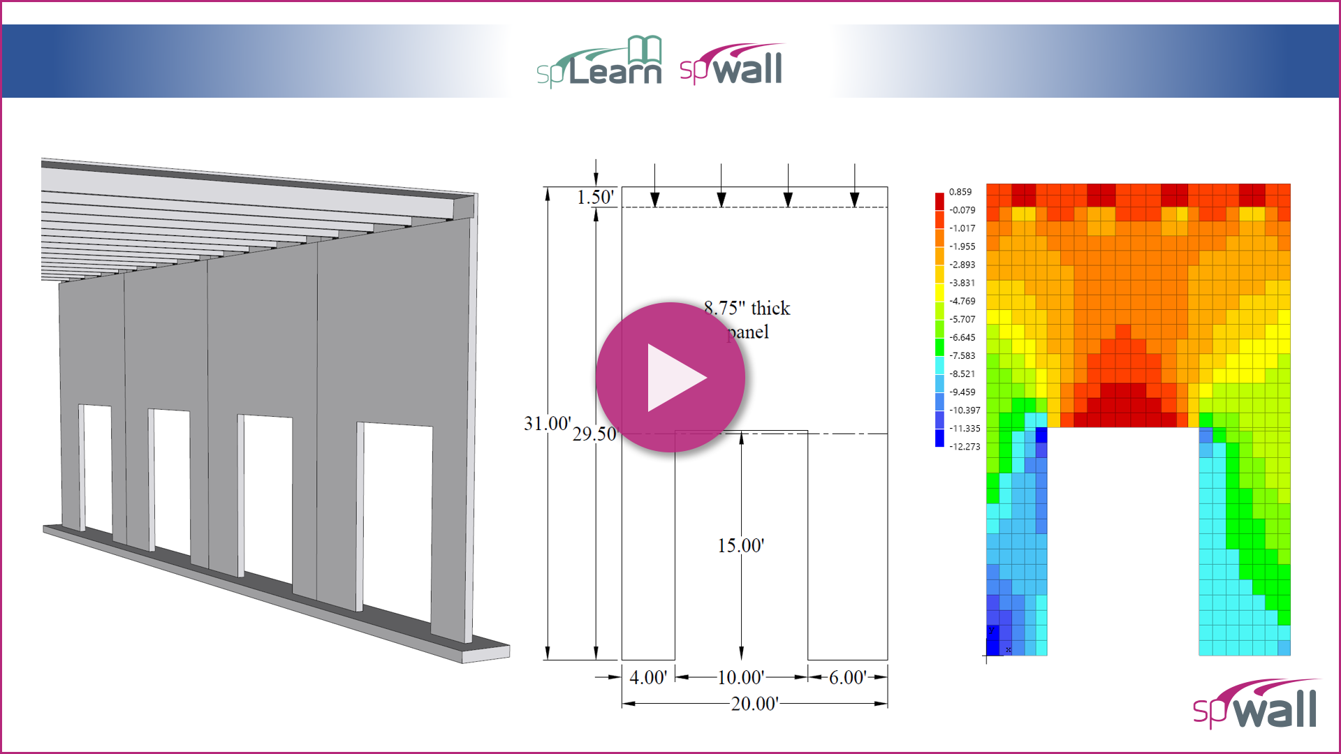
This video illustrates the analysis and design of structural reinforced concrete tilt-up wall panel with opening in a single-story warehouse (big-box) building. The demonstration focuses on the use of the American code (ACI 318-14) and the comprehensive procedure provided by ACI 551, and compares the hand solution with the analysis and design results obtained from spWall v10 engineering software program by StructurePoint.
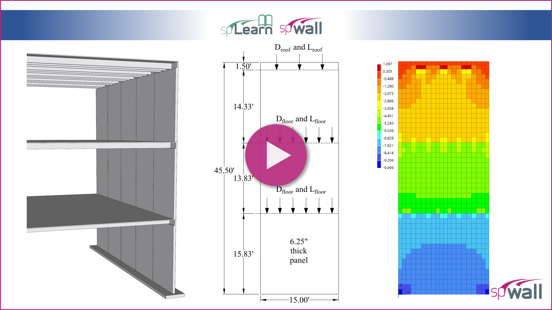
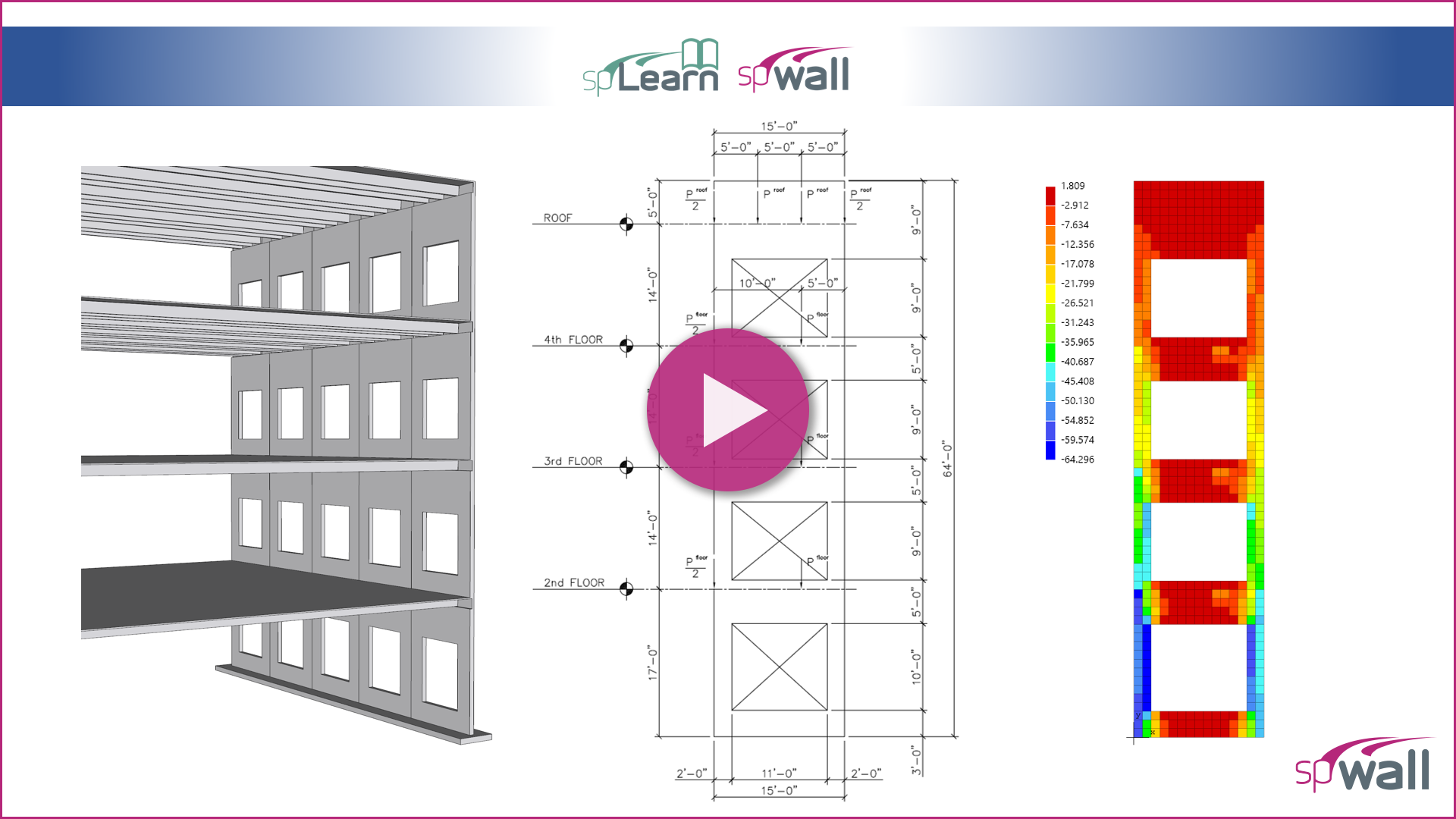
This video illustrates the analysis and design of structural reinforced concrete multi-story solid tilt-up wall panel in a multi-story building. The demonstration focuses on the use of the American code (ACI 318-14) and the comprehensive procedure provided by ACI 551, and compares the hand solution with the analysis and design results obtained from spWall v10 engineering software program by StructurePoint.
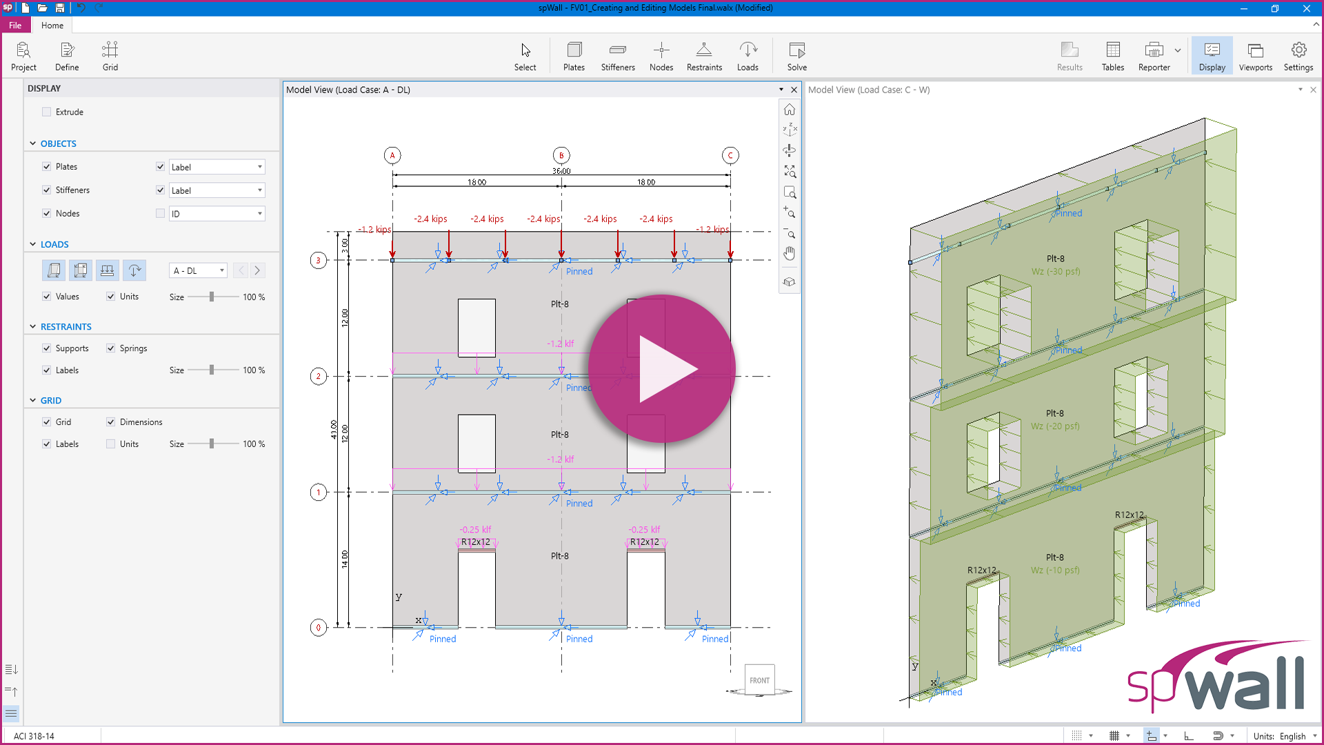
This video illustrates the analysis and design of structural reinforced concrete multi-story tilt-up wall panel with openings in a multi-story building. The demonstration focuses on the use of the American code (ACI 318-14) and the comprehensive procedure provided by ACI 551, and compares the hand solution with the analysis and design results obtained from spWall v10 engineering software program by StructurePoint.
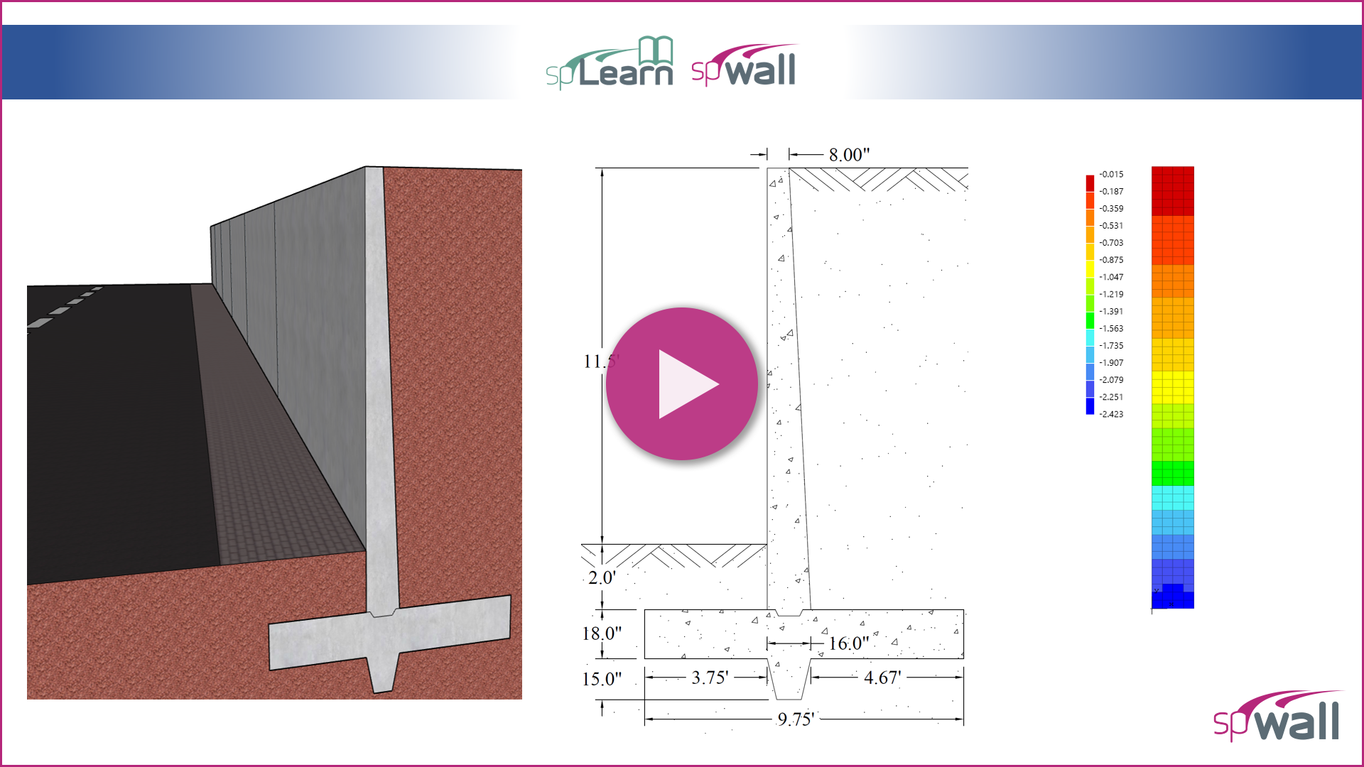
This video illustrates the analysis and design of a reinforced concrete tapered cantilever retaining wall. The demonstration focuses on the use of the American code (ACI 318-14), and compares the hand solution with the analysis and design results obtained from spWall v10 engineering software program by StructurePoint.
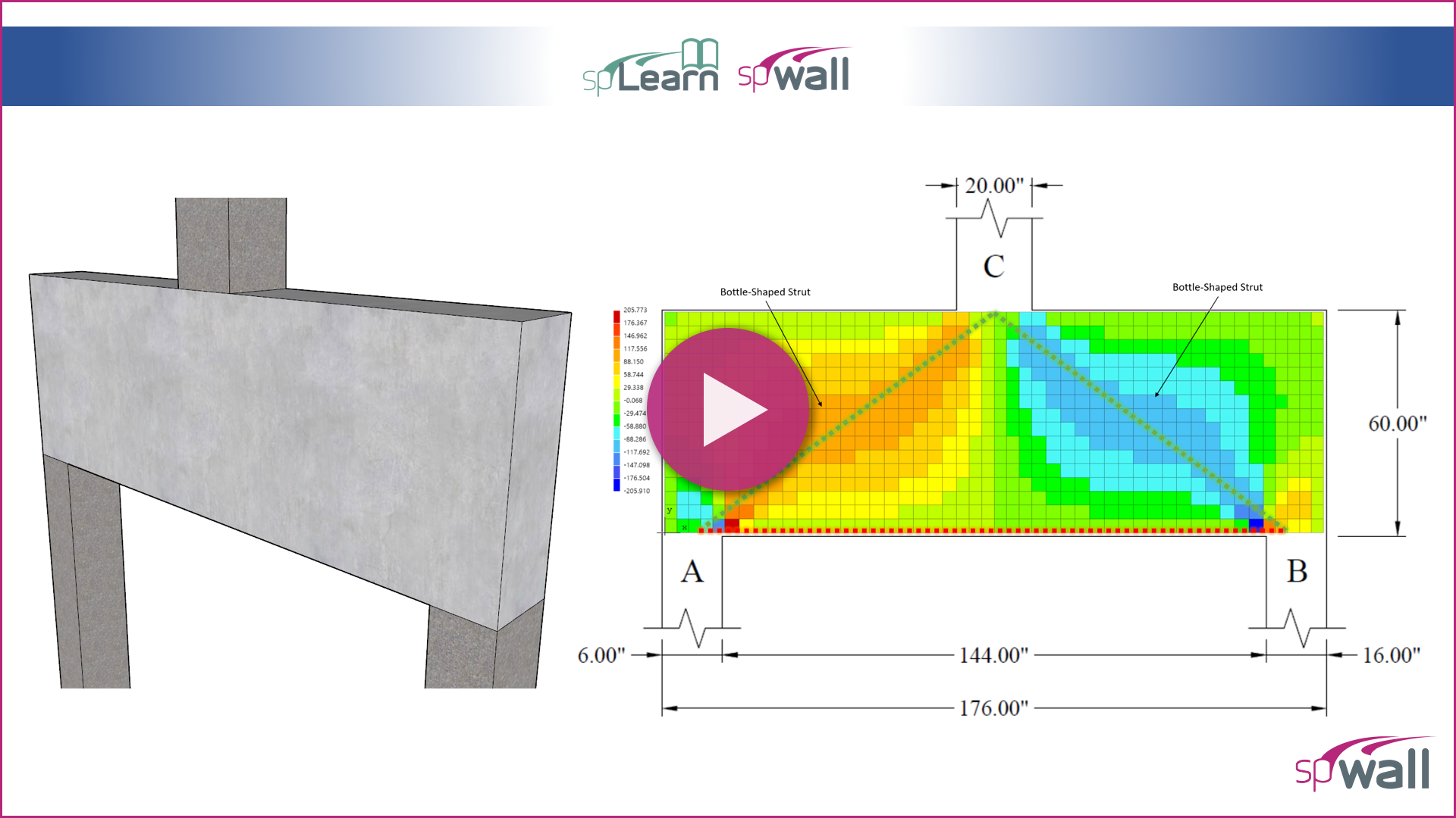
This video illustrates the analysis and design of a reinforced concrete transfer girder (deep beam). The demonstration focuses on the use of the Strut-and-Tie Method (STM) using the provisions of the American code (ACI 318-14), and compares the hand solution with the analysis and design results obtained from spWall v10 engineering software program by StructurePoint.
This video illustrates the analysis and design of a two-way flat slab with drop panels concrete floor system. The demonstration focuses on the use of the American code (ACI 318-14), and compares the hand solution using the Equivalent Frame Method (EFM) with the analysis and design results obtained from spSlab v5.50 engineering software program by StructurePoint.
This video illustrates the analysis and design of a two-way floor slab with beams concrete floor system. The demonstration focuses on the use of the American code (ACI 318-14), and compares the hand solution using the Equivalent Frame Method (EFM) with the analysis and design results obtained from spSlab v5.50 engineering software program by StructurePoint.
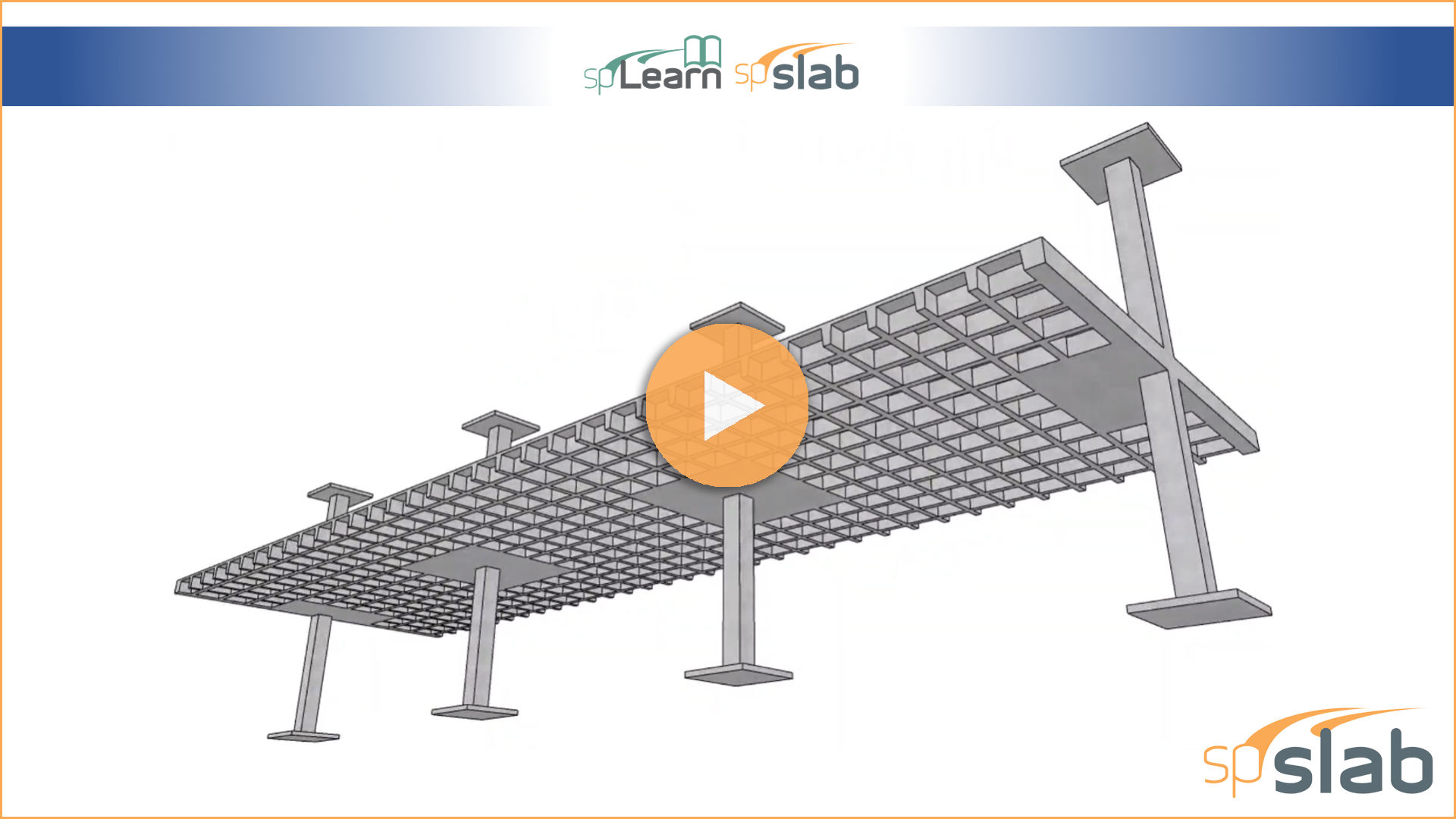
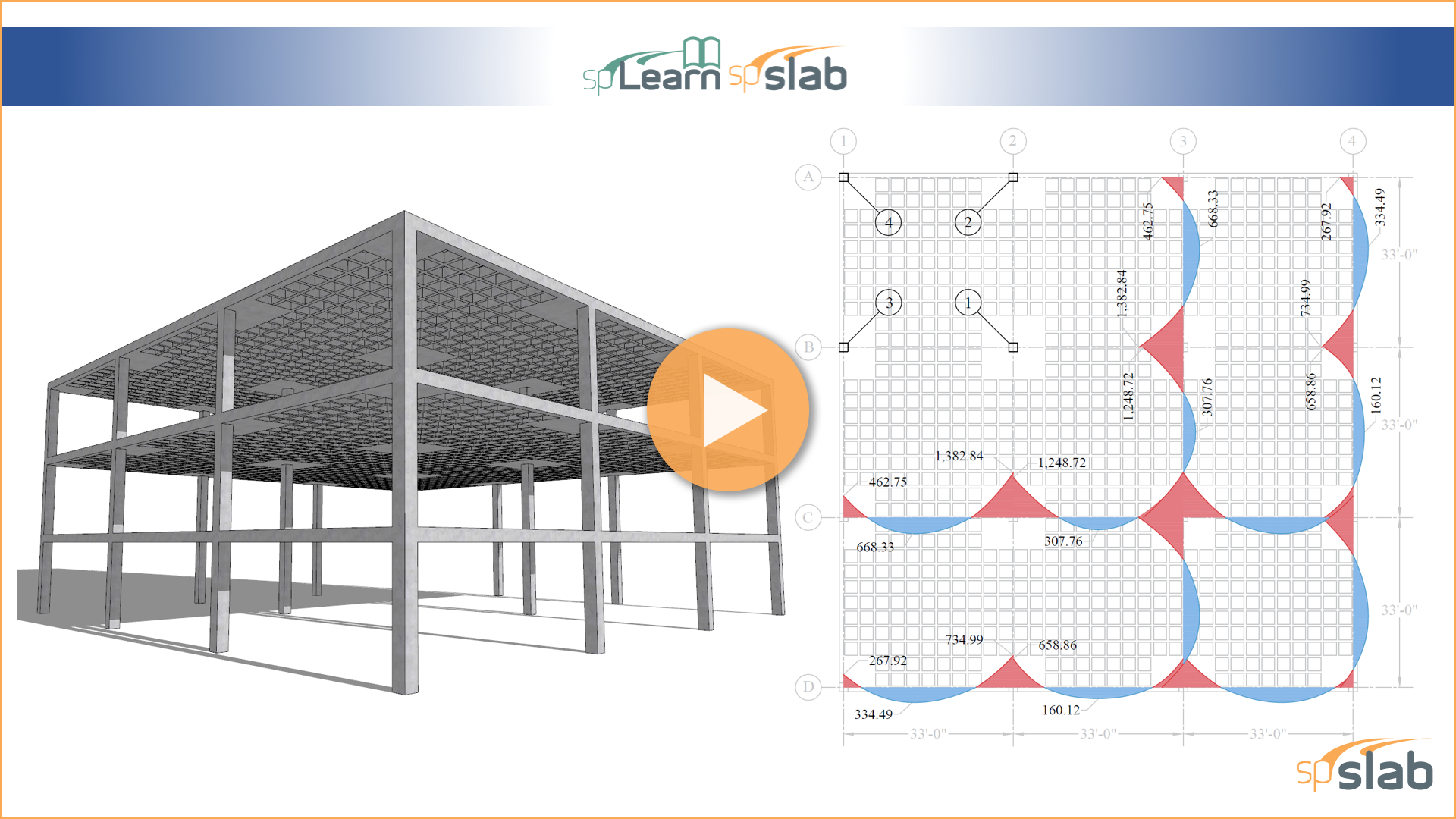
This video illustrates the analysis and design of a two-way joist waffle slab concrete floor system. The demonstration focuses on the use of the American code (ACI 318-14), and compares the hand solution using the Equivalent Frame Method (EFM) with the analysis and design results obtained from spSlab v5.50 engineering software program by StructurePoint.
This video illustrates the analysis and design of precast reinforced concrete bearing wall panel in a single-story building based on the provisions of the Canadian code (CSA A23.3-14). Simplified Equation Method is used to demonstrate hand calculation procedure and compare with finite element analysis results from spWall v10 engineering software program from StructurePoint.
This video provides an in-depth analysis and design of reinforced concrete shear walls, which are crucial for resisting lateral loads caused by wind and seismic forces. The demonstration focuses on the use of the Canadian code (CSA A23.3-14) and compares the hand solution with the analysis and design results obtained from spWall v10 engineering software program by StructurePoint.
The most significant upgrade to spColumn since its inception features a pioneering interface for intuitive modeling, fast results, logical reporting, and sophisticated tools all cleverly integrated in a simple and friendly workspace.
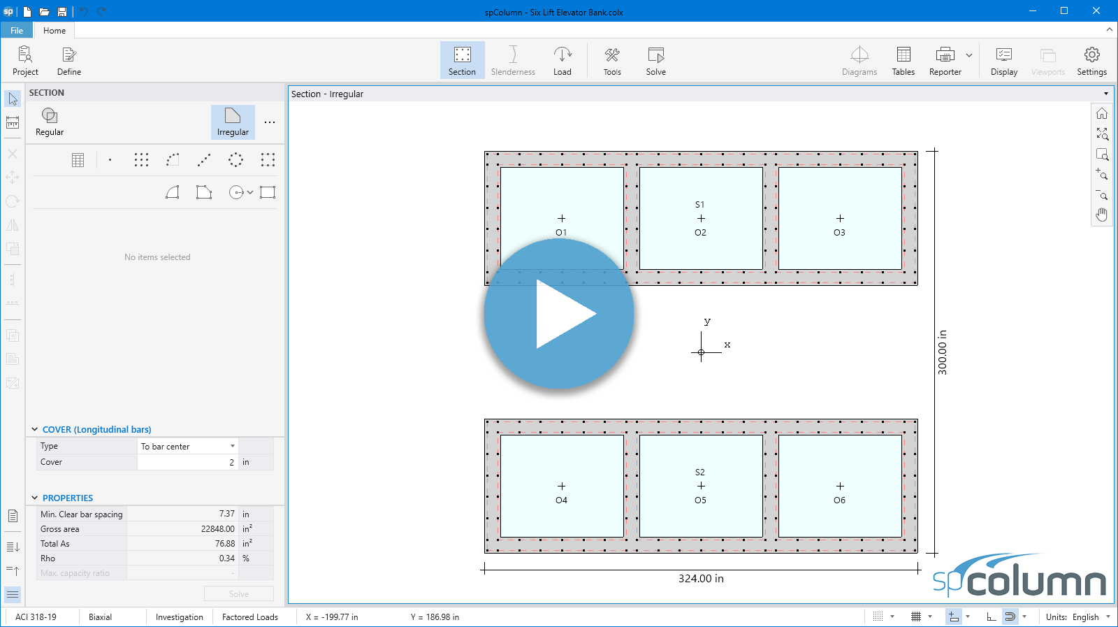
Learn how to create models with multiple solid shapes containing multiple openings using spColumn's quick and simple tools for building cores with elevator shafts and special bridge column and pile bent piers.
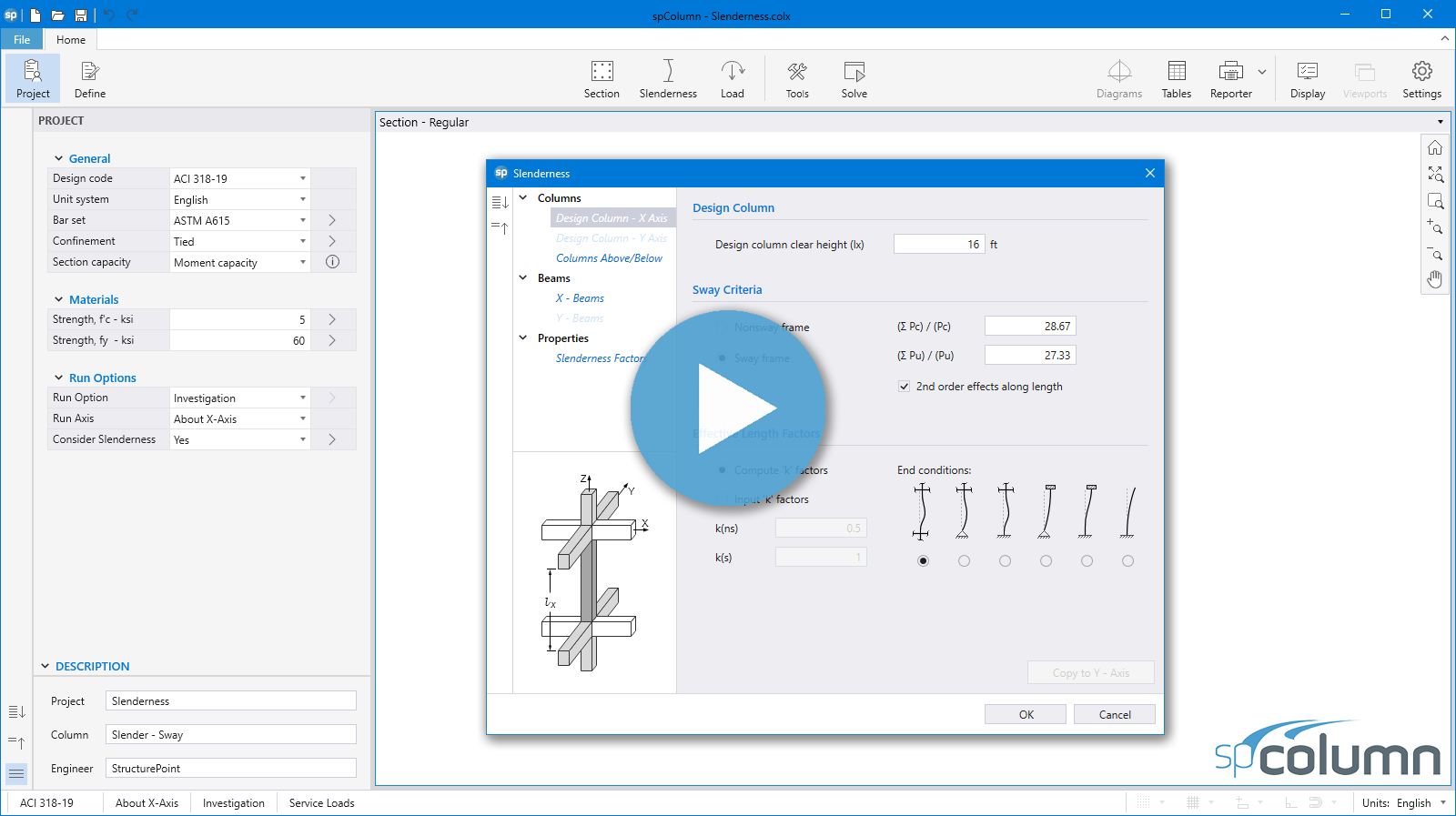
Examine column slenderness and stability in sway and non-sway frames and the impact of second order (P-Delta) effects on moment magnification using spColumn's powerful slenderness module.
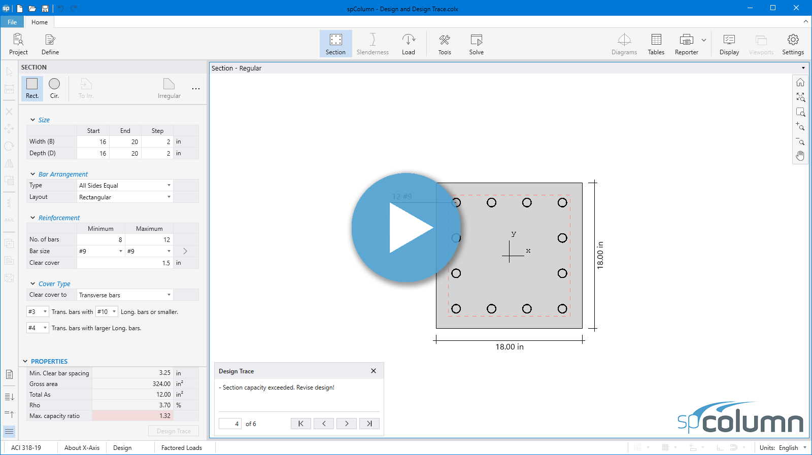
Don't investigate! Design. spColumn design features are less well known. Explore this powerful option in a new interface and observe design optimization while tracing intermediate and final results proposed by spColumn.
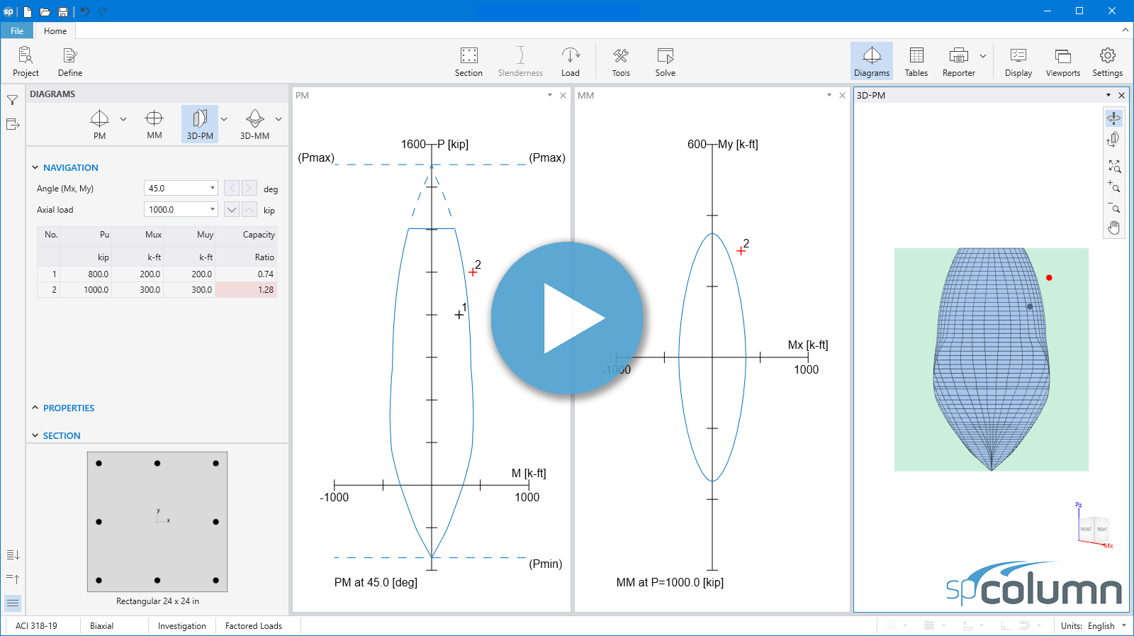
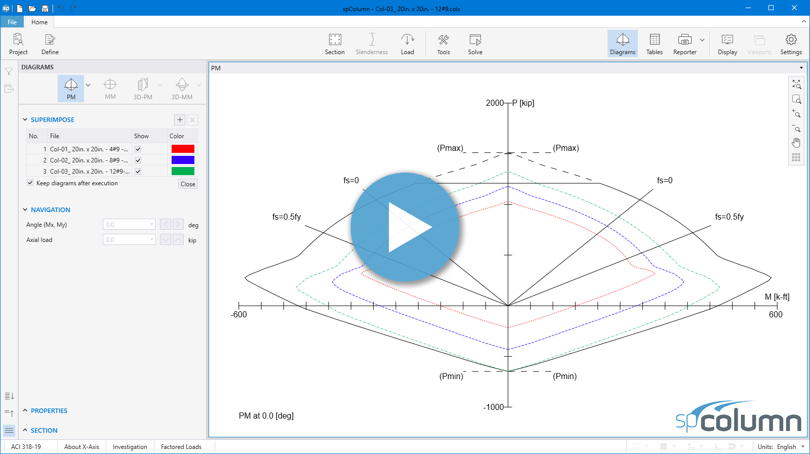
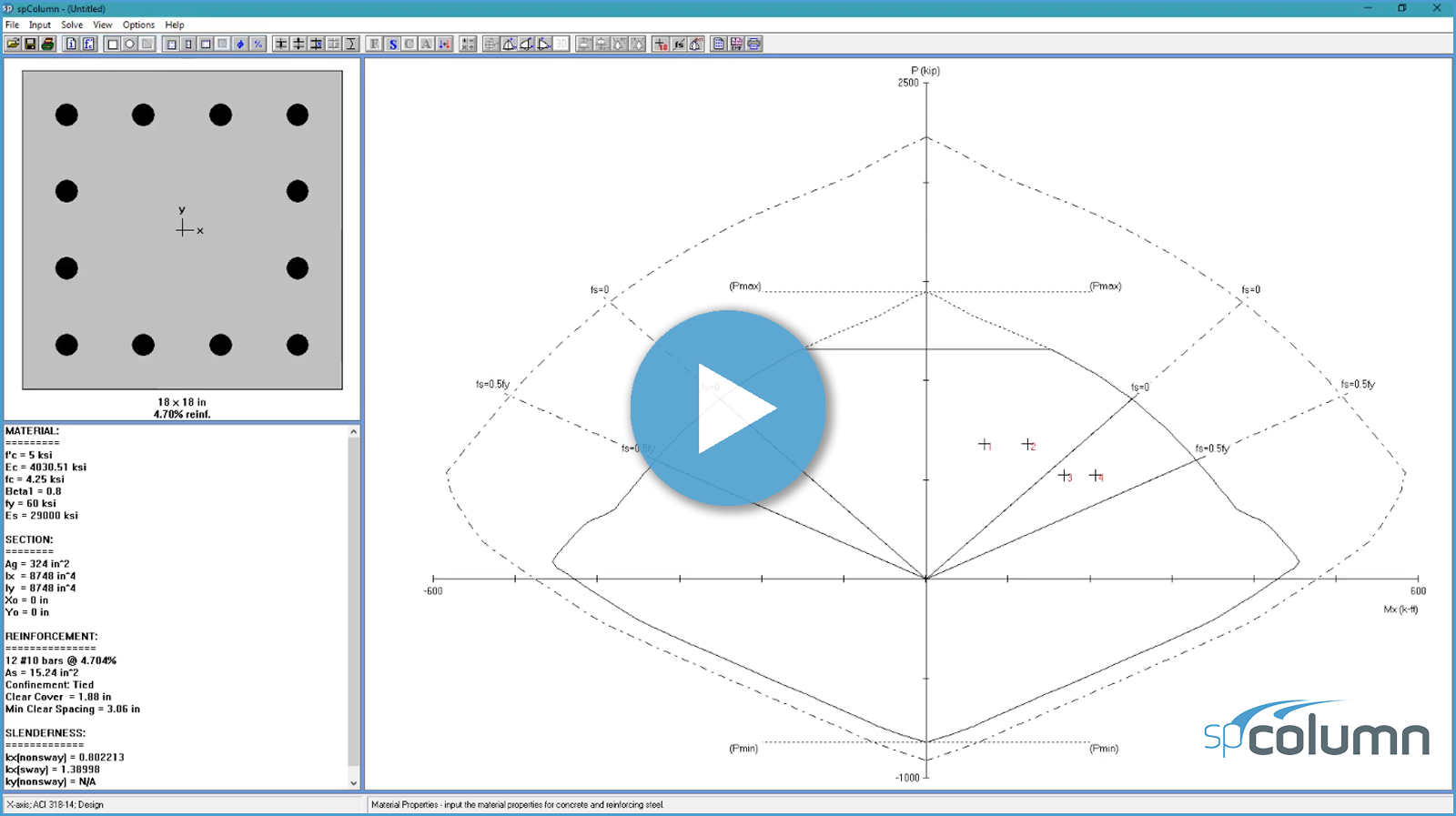
Superimpose and compare interaction diagrams of different sections in a new simple interface. Investigate detailing options, design envelopes, requests for changes or contrast as-built over designed conditions and make informed decisions quickly with the Superimpose tool.
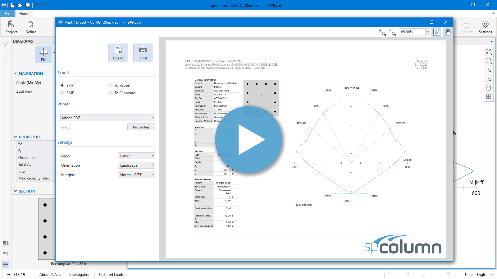
Evaluate Design Results and Interaction Diagrams quickly and make model adjustments on the fly using Print & Export Tools. The design summary can be easily customized and displayed on one page. Final modeling decisions can be communicated to the reporter and made part of the final report including interaction diagrams at any angle, Mx-My diagrams at any axial load level, 3D failure surfaces at any orientation, and superimposed multiple interaction diagrams.
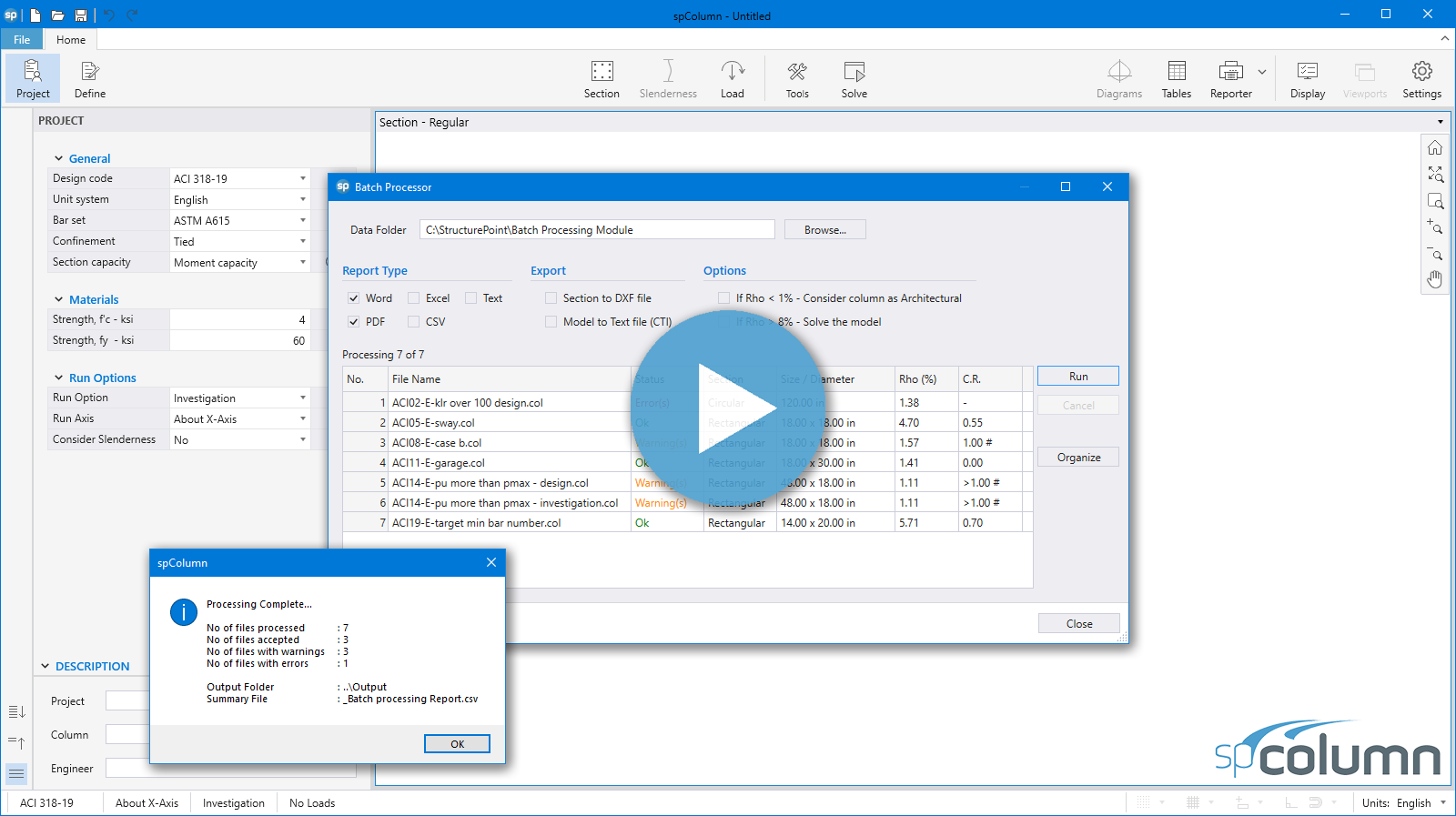
Run and solve hundreds of columns or walls in groups using the powerful spColumn batch processing tool. Load model files into the batch processor, specify preferred report types and criteria and sit back and watch the processing complete as design results are tabulated live with a summary report ready for review.
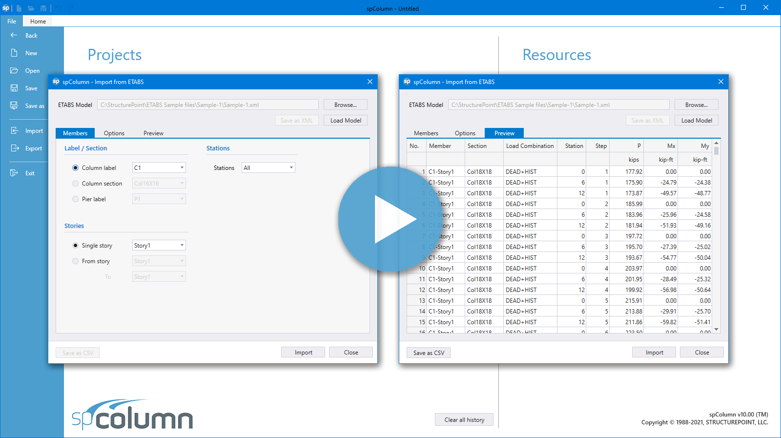
Import load data from the ETABS building analysis files using one of two file formats EDB or XML. Coupled with batch processing, this import feature allows fast iteration analysis & design cycles leveraging interoperability with ETABS.
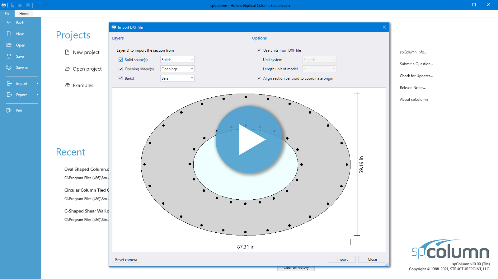
Learn how to import column, wall or pier sections as DXF files from software such as AutoCad to spColumn, and how to export the final section as DXF files from spColumn back to AutoCad.
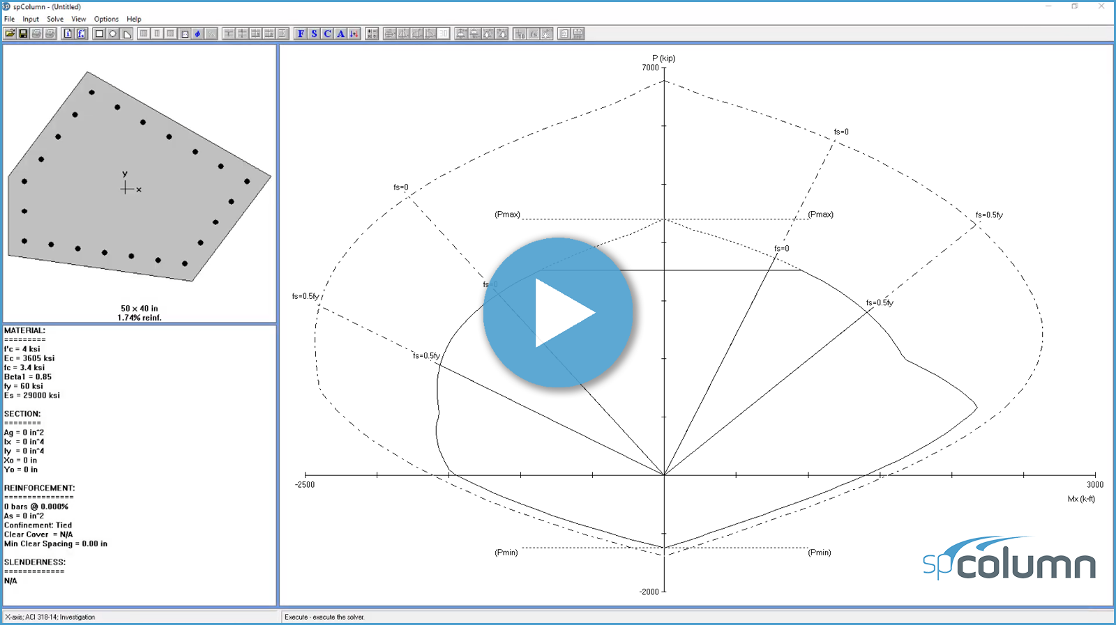
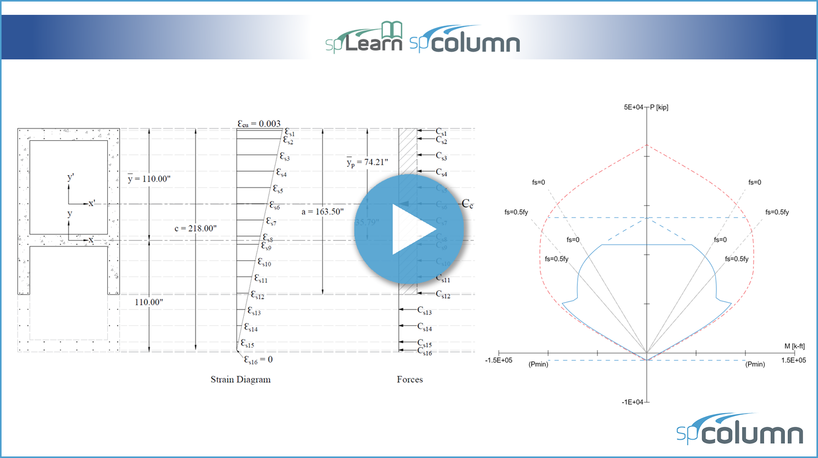
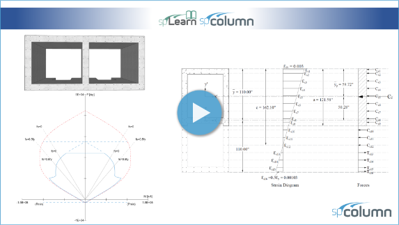
This video demonstrates the determination of design strength of a typical building elevator concrete core wall through the development of the axial - moment interaction diagram for the wall about the x-axis. Provisions of the American code (ACI 318-14) are used for hand calculations to determine seven control points on the interaction diagram along with a comparison with the results from the spColumn engineering software program by StructurePoint. Exact values from the complete interaction diagram are shown as generated by spColumn program.
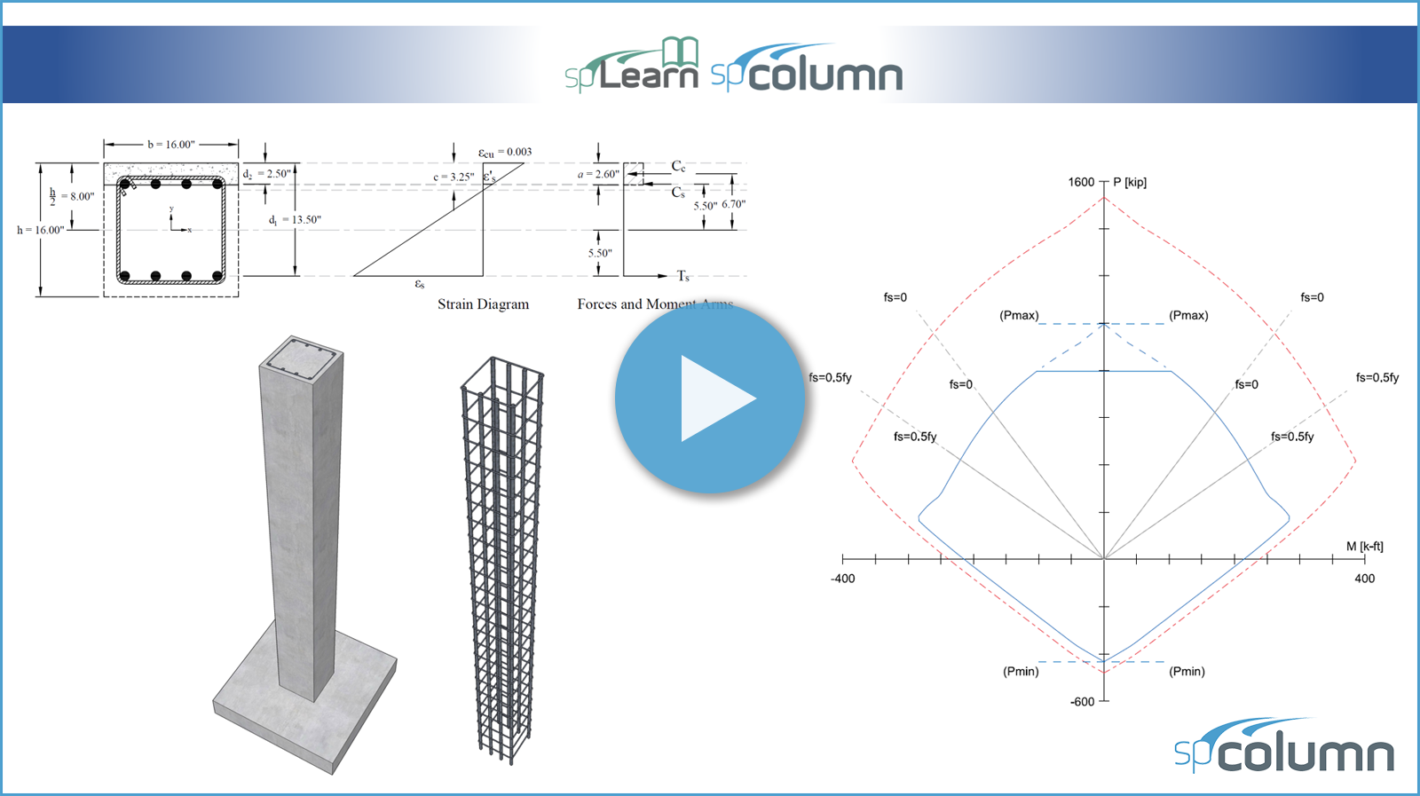
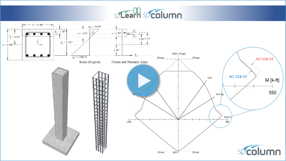
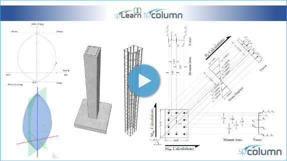
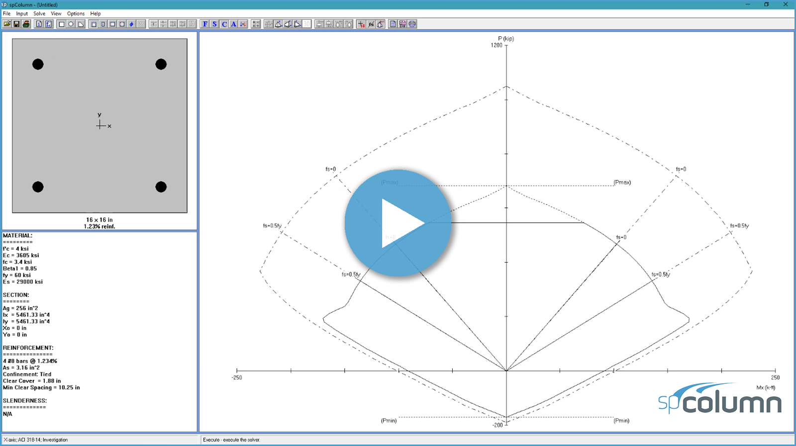
This video demonstrates the development of the interaction diagram for a square tied concrete column about the x-axis based on the provisions of the American code (ACI 318-19). The Seven control points on the interaction diagram are determined and compared with the calculated values in the Reference and with exact values from the complete interaction diagram generated by spColumn v10 engineering software program from StructurePoint.
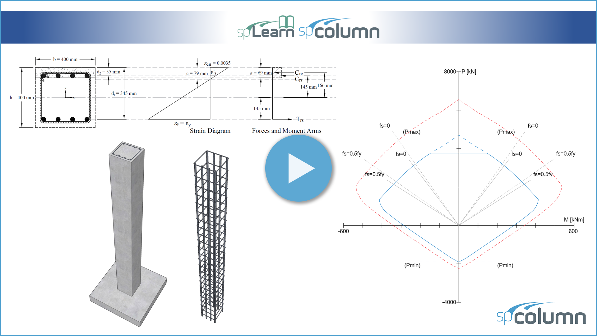
This video demonstrates the development of the interaction diagram for a square tied concrete column about the x-axis based on the provisions of the Canadian code (CSA A23.3-19). The Six control points on the interaction diagram are determined and compared with exact values from the complete interaction diagram generated by spColumn v10.10 engineering software program from StructurePoint.
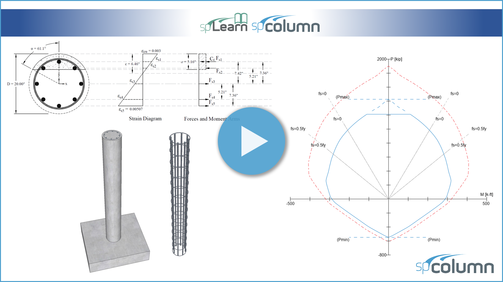
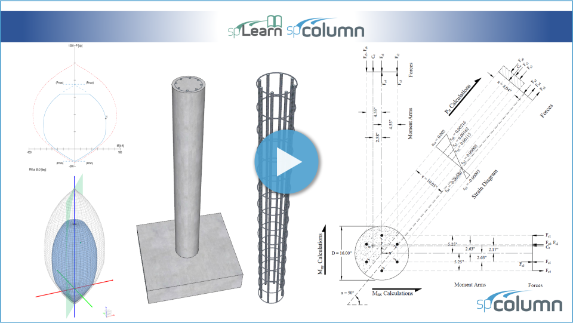
This video demonstrates the development of the interaction diagram for a circular spiral concrete column about the x-axis based on the provisions of the American code (ACI 318-19). The Seven control points on the interaction diagram are determined and compared with the calculated values in the Reference and with exact values from the complete interaction diagram generated by spColumn v10 engineering software program from StructurePoint.
This video demonstrates the development of the interaction diagram for a square tied concrete column about the x-axis with high strength reinforcing bars (HSRB) based on the provisions of the American code (ACI 318-19). The Seven control points on the interaction diagram are determined and compared with exact values from the complete interaction diagram generated by spColumn v10 engineering software program from StructurePoint.
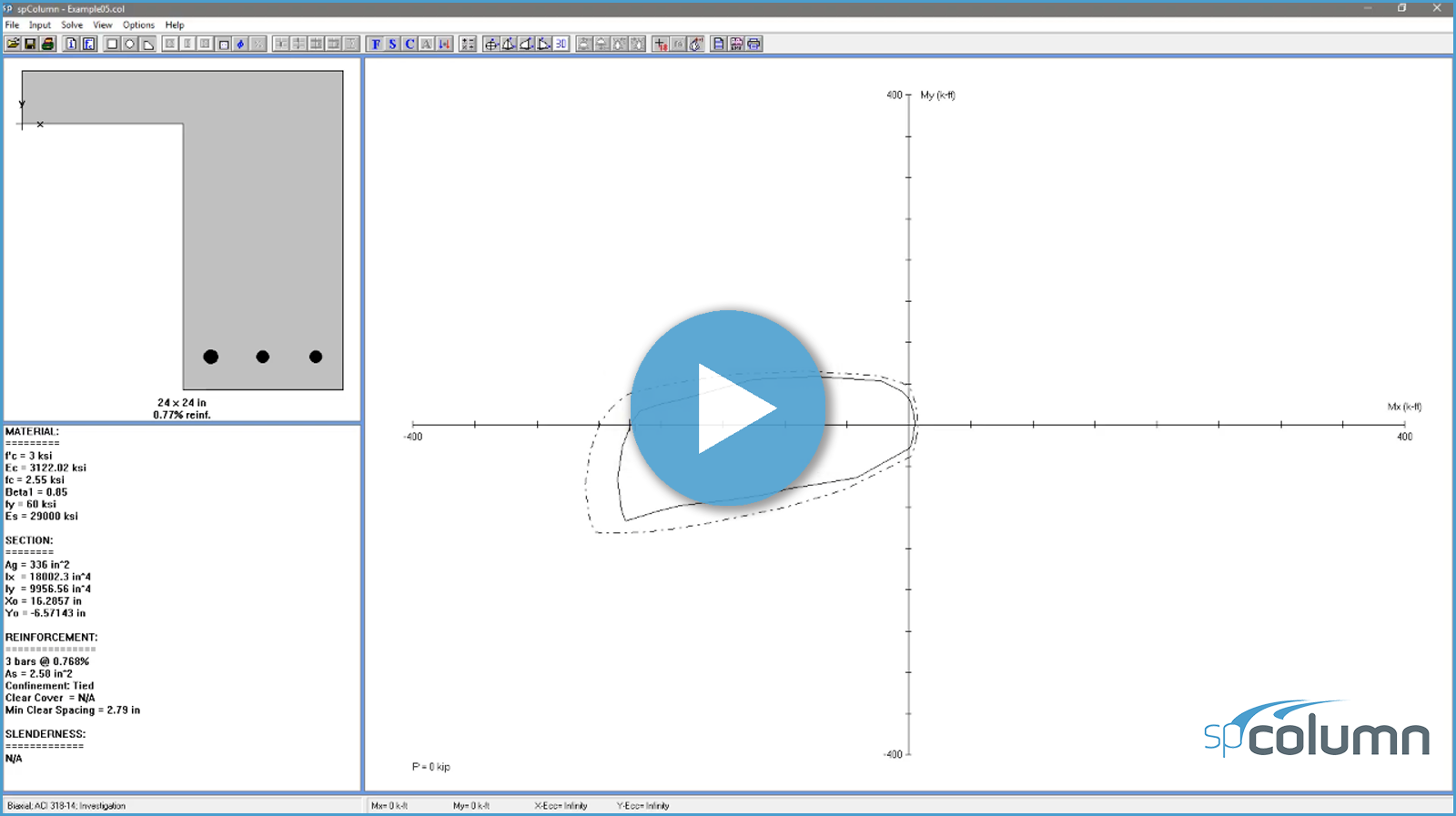
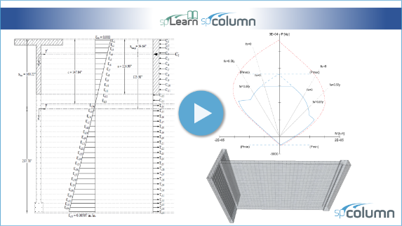
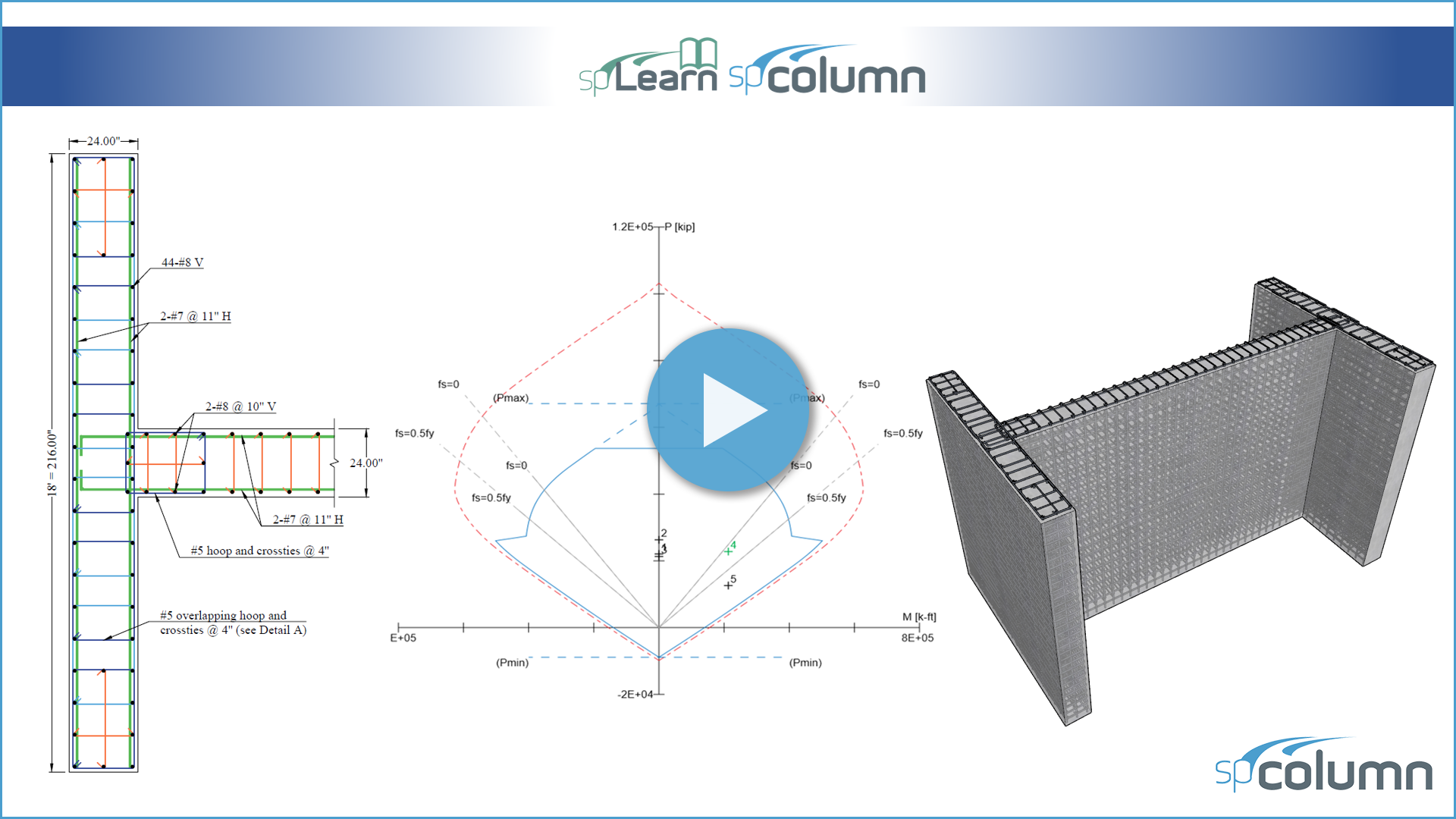
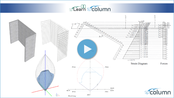
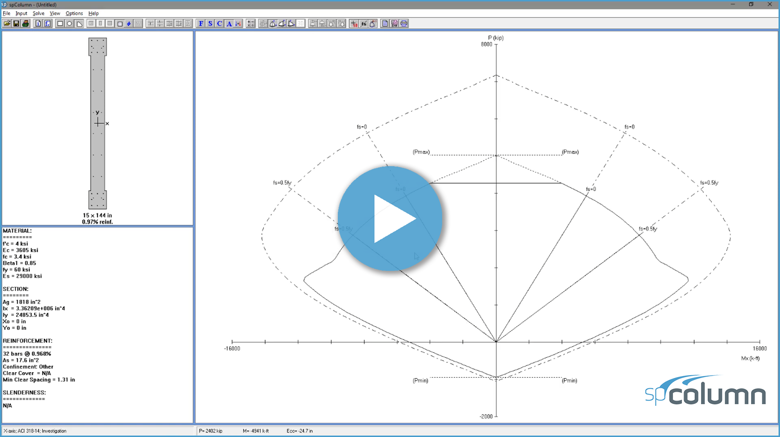
This video demonstrates the development of the P-M interaction diagram for a barbell concrete shear wall with unsymmetrical boundary elements based on the provisions of the American code (ACI 318-19). The T-shaped formation comprises the basement retaining wall (Tee flange), the stem serving as the shear wall (Tee web), and the first building column. The differences between the interaction diagram for irregular and regular wall sections are highlighted. The results obtained from the hand calculations were compared with the complete interaction diagram generated by spColumn v10 engineering software program.
This video demonstrates the strength calculations of a typical core wall based on the provisions of the American code (ACI 318-19). The results obtained from the hand calculations were compared with the results obtained by spColumn v10 engineering software program.
This video demonstrates the design procedure and steps of a special structural (shear) wall in the first story of a 30-story building providing lateral and gravity load resistance based on the provisions of the American code (ACI 318-19). The calculated results are compared with the values presented in the Reference and exact values from spColumn v10.10 engineering software program from StructurePoint.
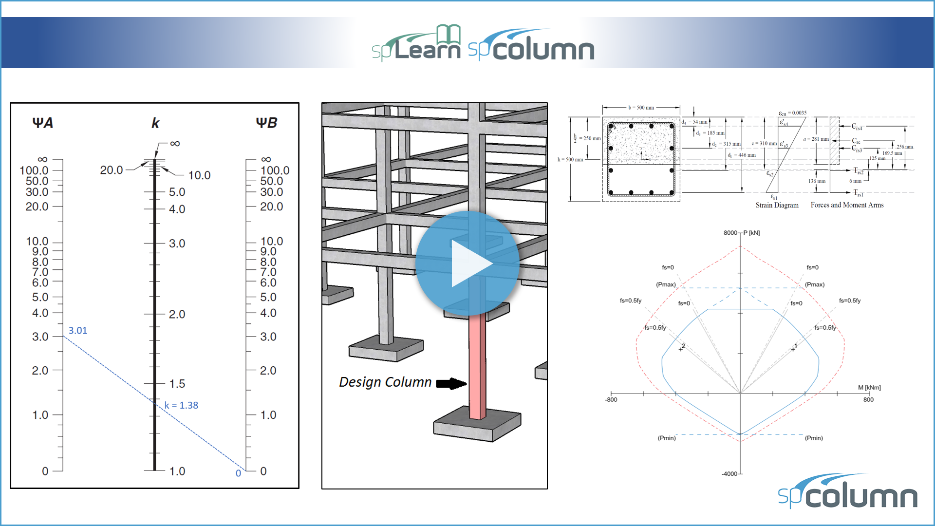
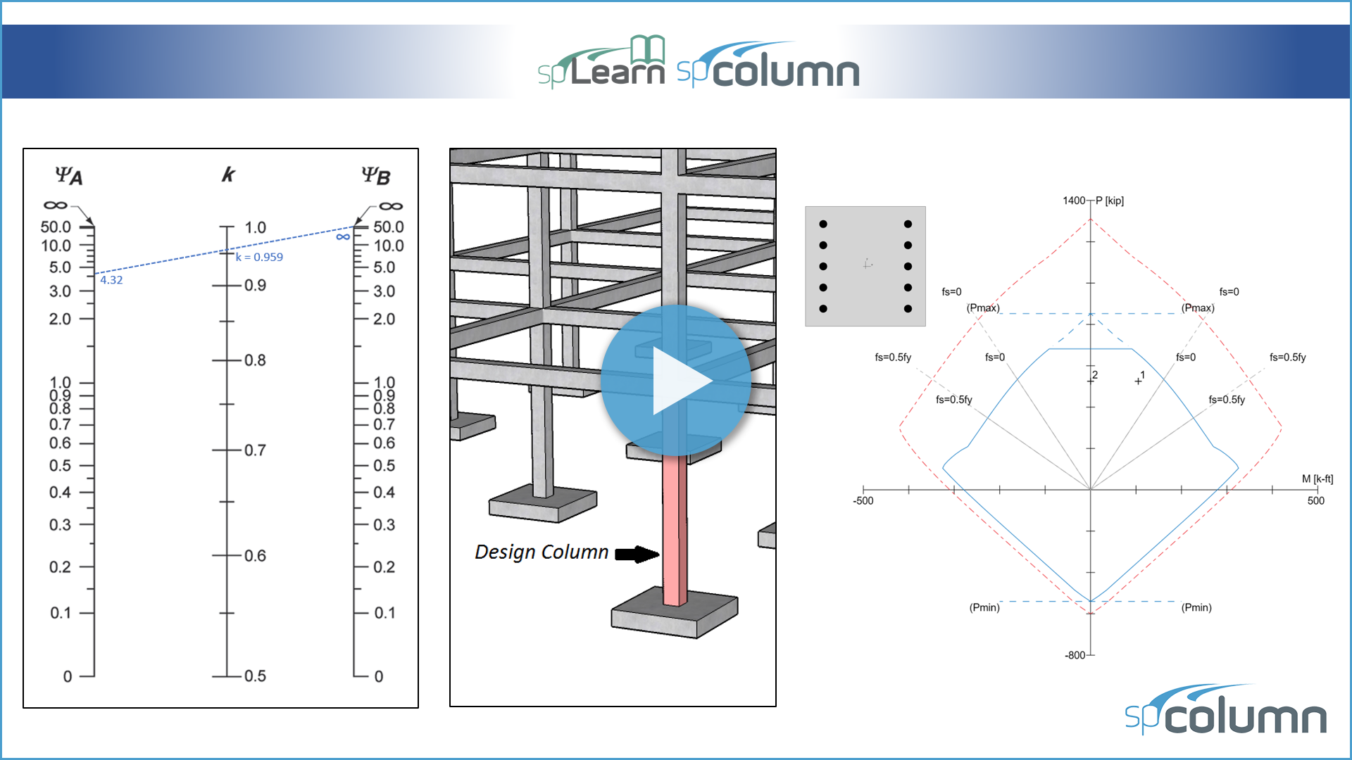
This video demonstrates the evaluation of slenderness effect for columns in a sway frame based on the provisions of the American code (ACI 318-19) by designing a first story exterior column in multistory reinforced concrete building (22" x 22" column section). The calculated results are compared with exact values from spColumn v10 engineering software program from StructurePoint.
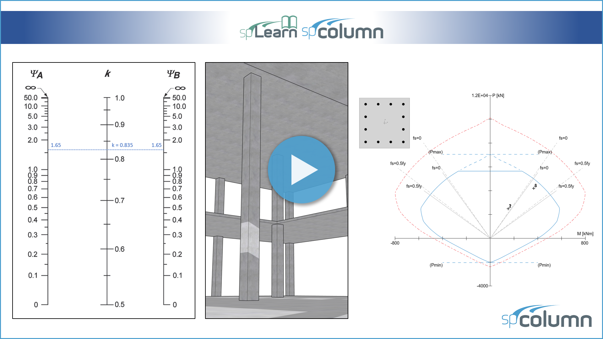
This video demonstrates the evaluation of slenderness effect for columns in a sway frame based on the provisions of the Canadian code (CSA A23.3-19) by designing a first story exterior column in multistory reinforced concrete building (500 × 500 mm column section). The calculated results are compared with exact values from spColumn v10.10 engineering software program from StructurePoint.
This video demonstrates the evaluation of slenderness effect for columns in a sway frame based on the provisions of the American code (ACI 318-19) by designing a first story exterior column in multistory reinforced concrete building (18" x 18" column section). The calculated results are compared with exact values from spColumn v10 engineering software program from StructurePoint.
This video demonstrates the evaluation of slenderness effects for columns in a non-sway multistory reinforced concrete frame based on the provisions of the American code (ACI 318-19) by determining the adequacy of the square tied column, which is an exterior first floor column. The calculated results are compared with the values presented in the Reference and exact values from spColumn v10 engineering software program.
This video demonstrates the evaluation of slenderness effects for columns in a non-sway multistory reinforced concrete frame based on the provisions of the Canadian code (CSA A23.3-19) by determining the adequacy of the square tied column, which is a two-story high column in the middle of an atrium opening. The calculated results are compared with exact values from spColumn v10.10 engineering software program from StructurePoint.
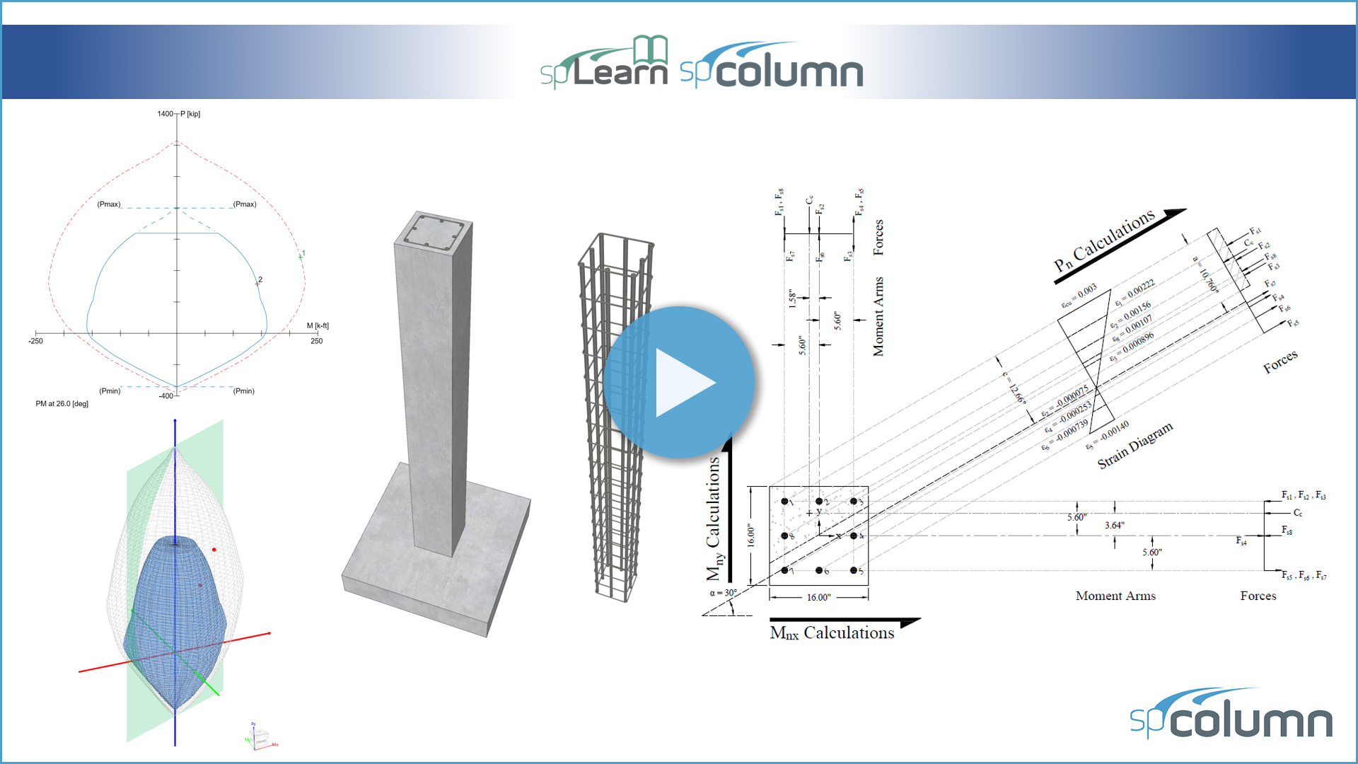
This video demonstrates the determination of the design axial strength and biaxial moment strengths for a specific neutral axis location and orientation based on the provisions of the American code (ACI 318-19). The calculated values are compared with the values from the reference and the exact values from spColumn v10 engineering software program from StructurePoint. The steps to develop the three-dimensional failure surface (interaction diagram) using spColumn v10 are shown in detail as well.
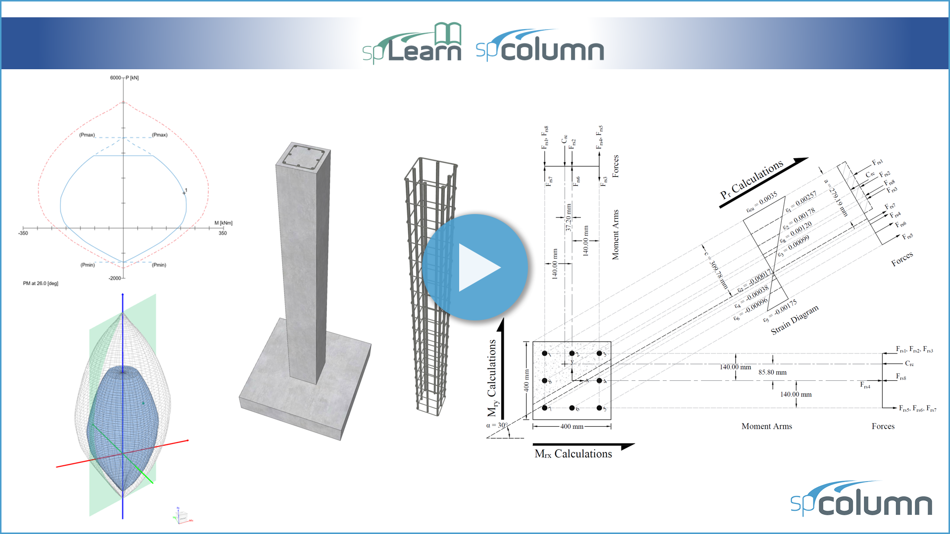
This video demonstrates the determination of the factored axial load resistance and factored moments resistance for a specific neutral axis location and orientation based on the provisions of the Canadian code (CSA A23.3-19). The calculated values are compared with the exact values from spColumn v10 engineering software program from StructurePoint. The steps to develop the three-dimensional failure surface (interaction diagram) using spColumn v10 are shown in detail as well.
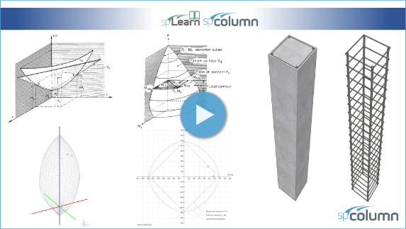
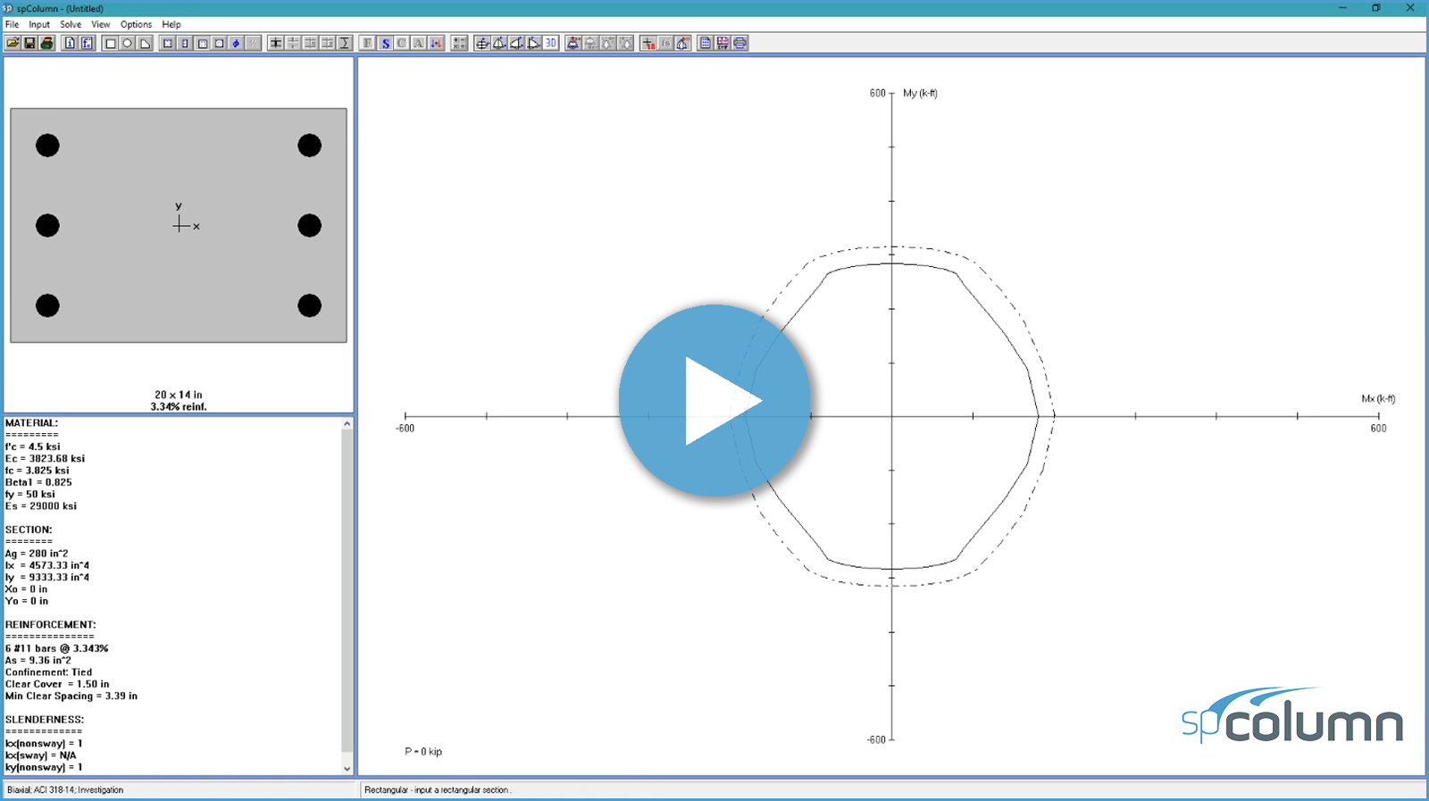
This video demonstrates the determination of the biaxial flexural strength of a rectangular reinforced concrete column at a particular nominal axial strength with a moment ratio of biaxial bending moments in the X and Y direction based on the provisions of the American code (ACI 318-19). The calculated values of the column biaxial bending strength are compared with the values from the reference and the exact values from spColumn v10 engineering software program from StructurePoint. The steps to develop the three-dimensional failure surface (interaction diagram) using spColumn v10 are shown in detail as well.
This video demonstrates the determination of C-shaped core wall design axial strength and biaxial moment strengths for a specific neutral axis location and orientation based on the provisions of the American code (ACI 318-19). The calculated values are compared with the values from spColumn v10 engineering software program from StructurePoint. The steps to develop the three-dimensional failure surface (interaction diagram) using spColumn v10 are shown in detail as well.
This video demonstrates the determination of spiral reinforced circular concrete column design axial strength and biaxial moment strengths for a specific neutral axis location and orientation based on the provisions of the American code (ACI 318-19). The calculated values are compared with the values from spColumn v10 engineering software program from StructurePoint. The steps to develop the three-dimensional failure surface (interaction diagram) using spColumn v10 are shown in detail as well.
This video demonstrates the determination of a column section capacity required to resist factored load and biaxial moments utilizing the most commonly used approximate manual design procedures and the exact design procedure. The following approximate procedures are discussed in this example:
- Bresler Reciprocal Load Method,
- Bresler Load Contour Method,
- PCA Load Contour Method.
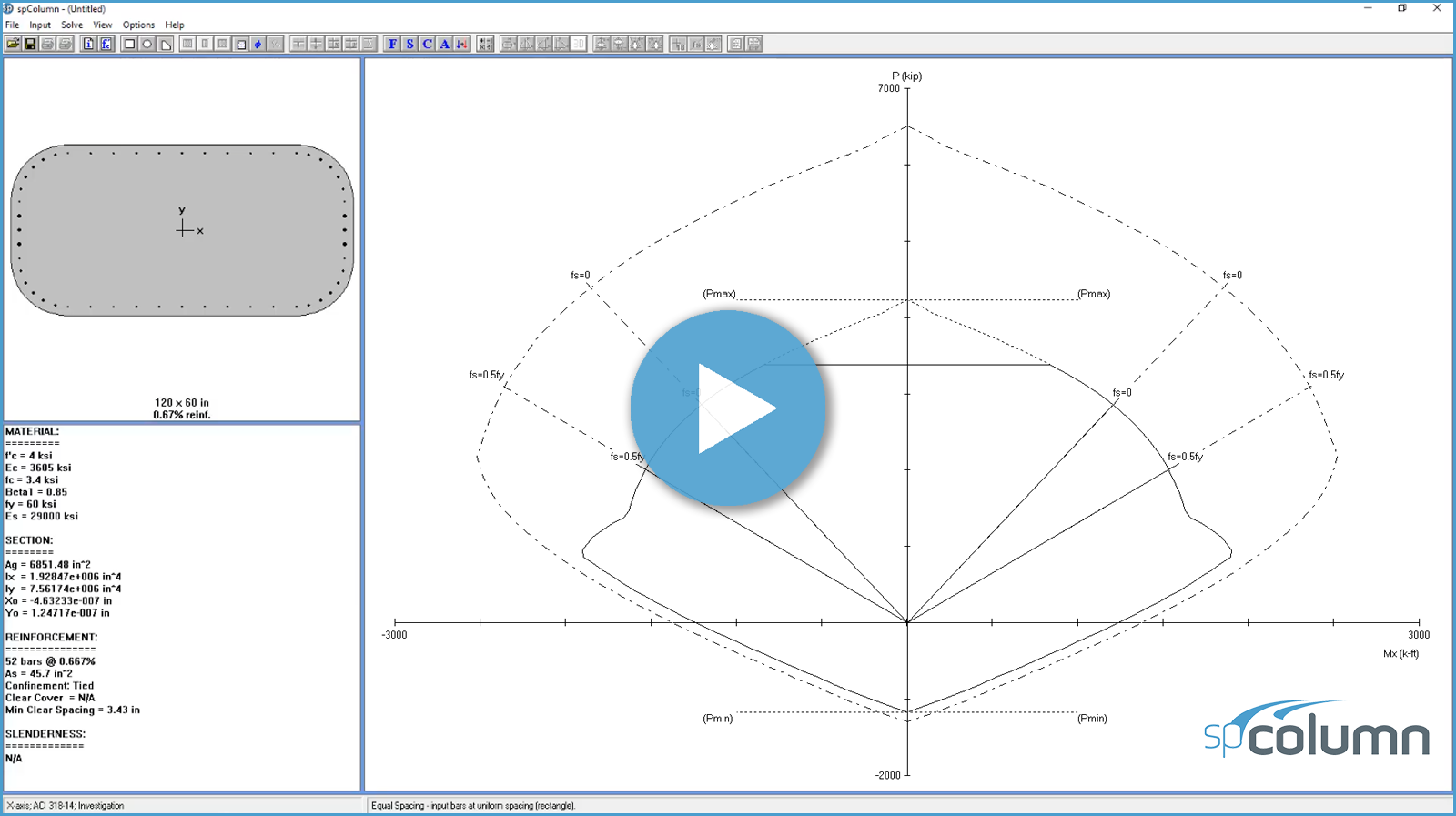
This tutorial video shows how to calculate the load moment capacities for a square column using spColumn.
This tutorial video shows how to check the adequacy of a dumbbell shear wall using spColumn.
This tutorial video shows how to design a square column in a sway frame using spColumn.
This tutorial video shows how to check the adequacy of a slender column in a nonsway frame using spColumn.
This tutorial video shows how to check the adequacy of a short column with rectangular section using spColumn.
This tutorial video shows how to calculate the load moment capacity for an irregular section using spColumn.
An introduction to major features of the spColumn model editor (spSection) to create any type of regular or irregular sections.
A tutorial video demonstration on how to create an irregular bridge pier section using spColumn model editor.
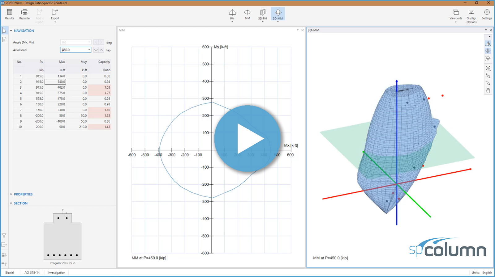
An overview of the 2D3DView module in spColumn, with new features for viewing and navigating 2D diagrams and 3D surfaces.
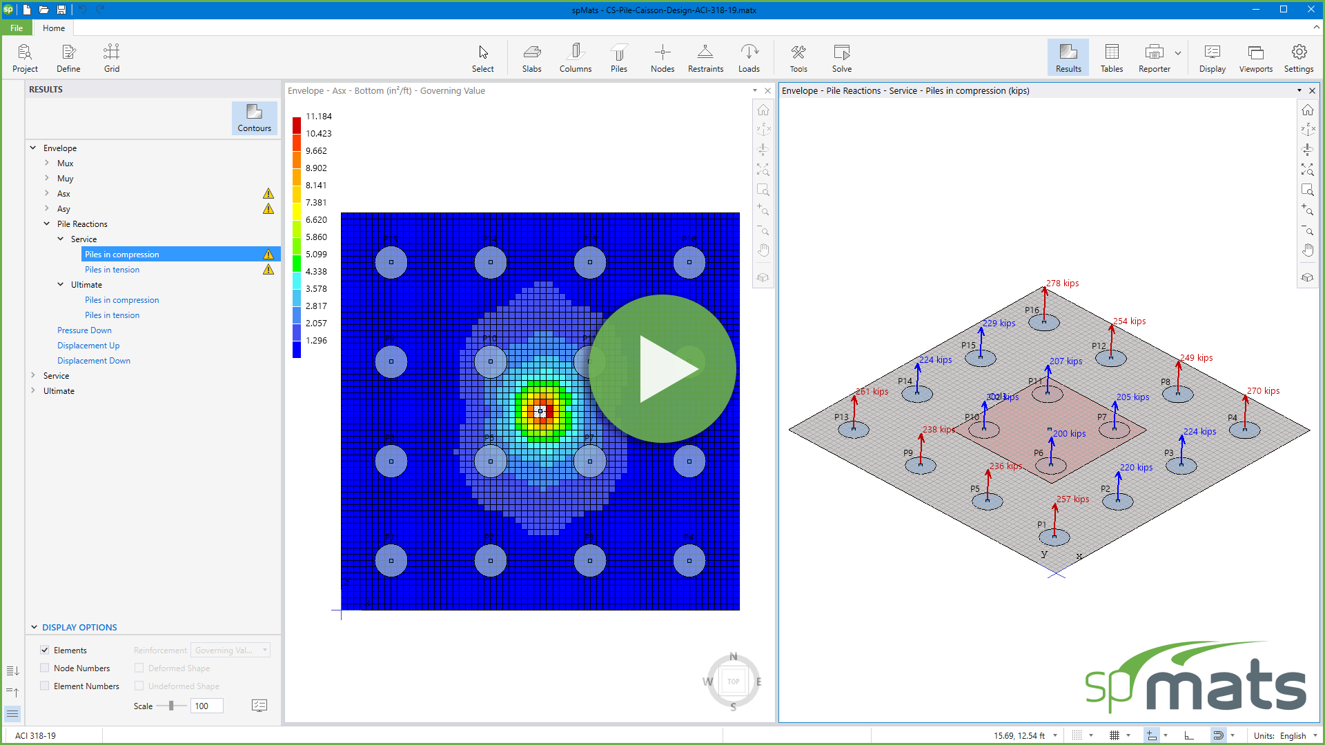
Discover the powerful new features in spMats v10.50, the industry-leading structural engineering software for reinforced concrete slab and foundation design. This update enhances productivity, accuracy, and code compliance with improvements to reinforcement design, pile reactions, drafting tools, mesh quality, and more.
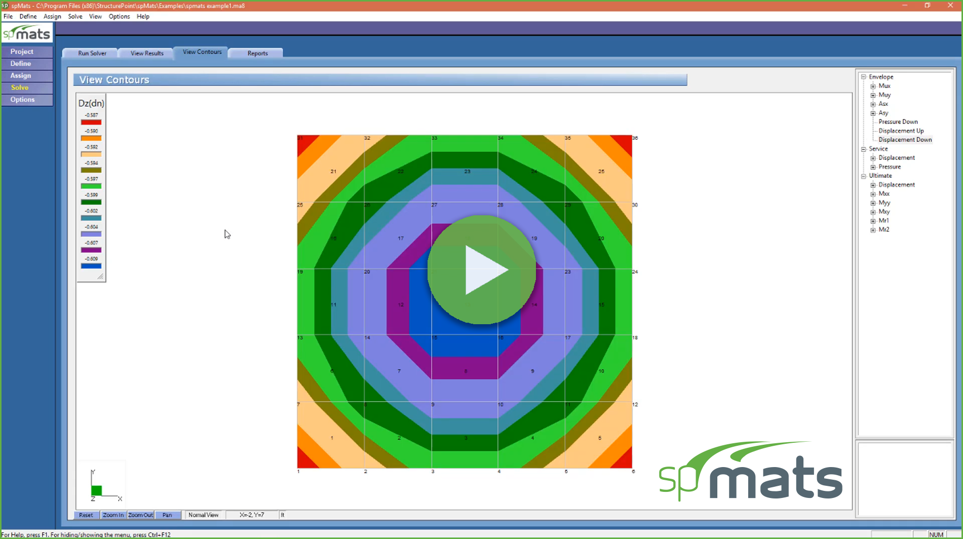
A brief description of spMats new interface, enhanced modeling and reporting features.
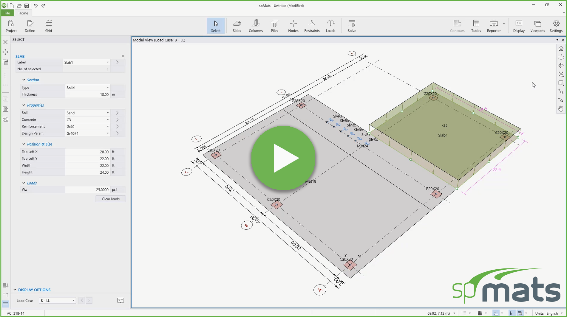
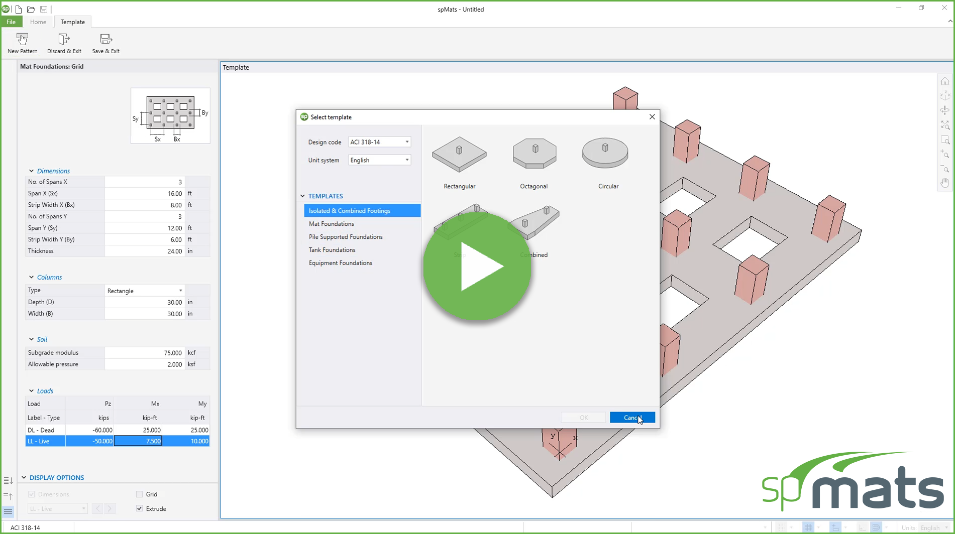
Tutorial video shows how to create models, define and assign boundary conditions and loading using spMats new interface.
Tutorial video shows how to edit and navigate existing models using spMats new interface.
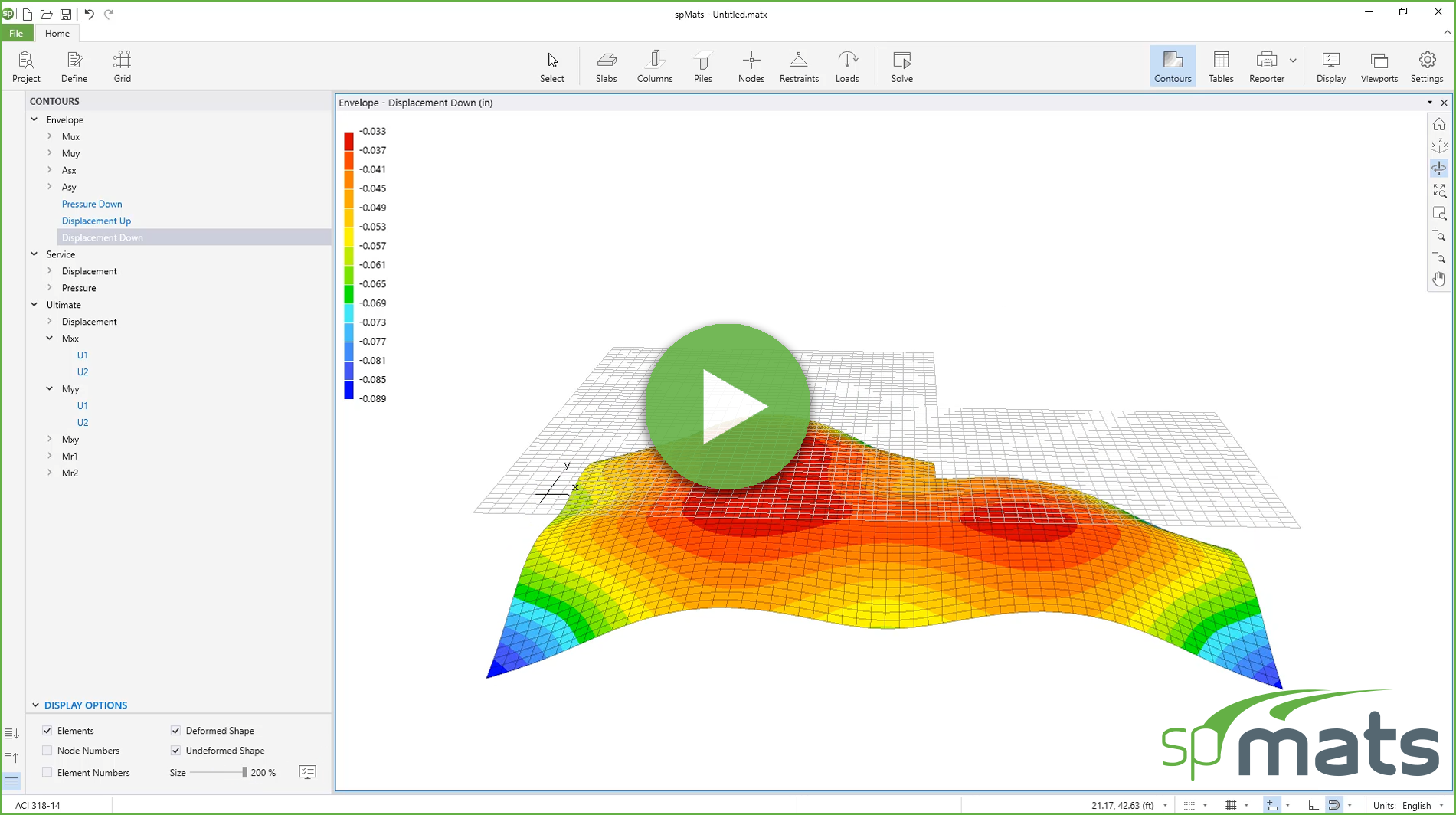
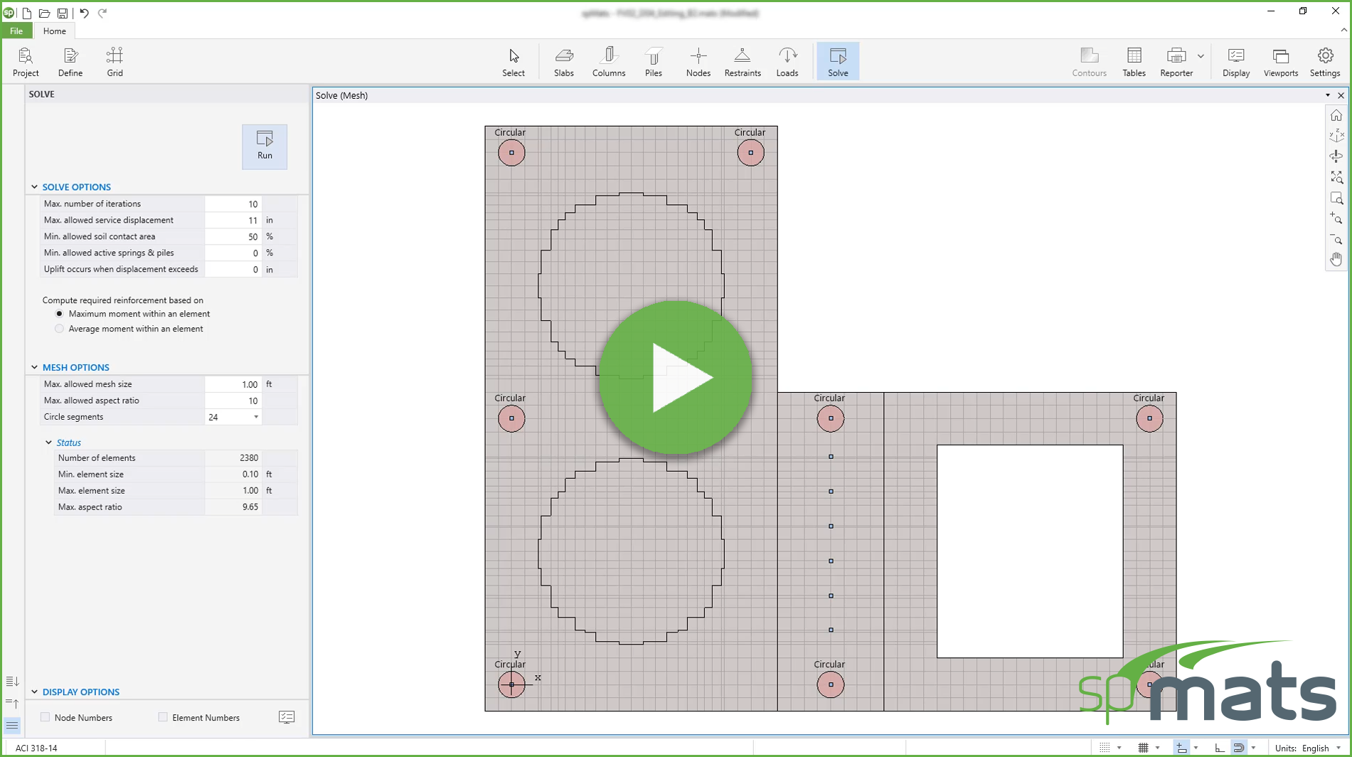
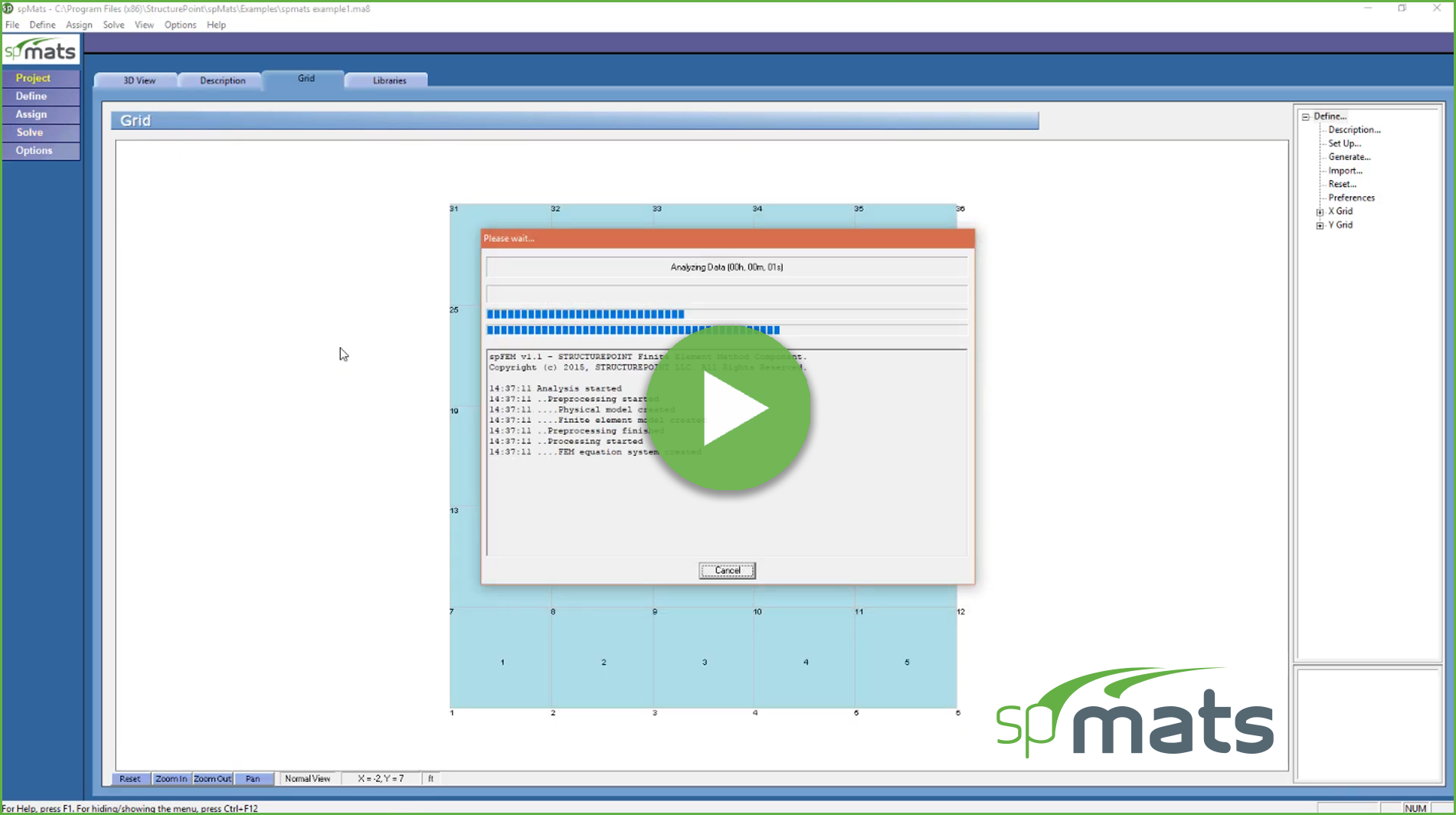
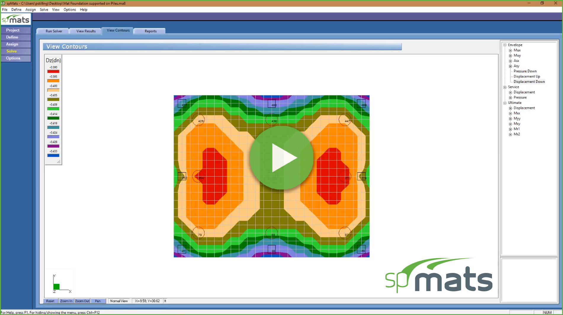
Tutorial video to demonstrate the new spMats solve options, Mesh optimization, graphical results and tables.
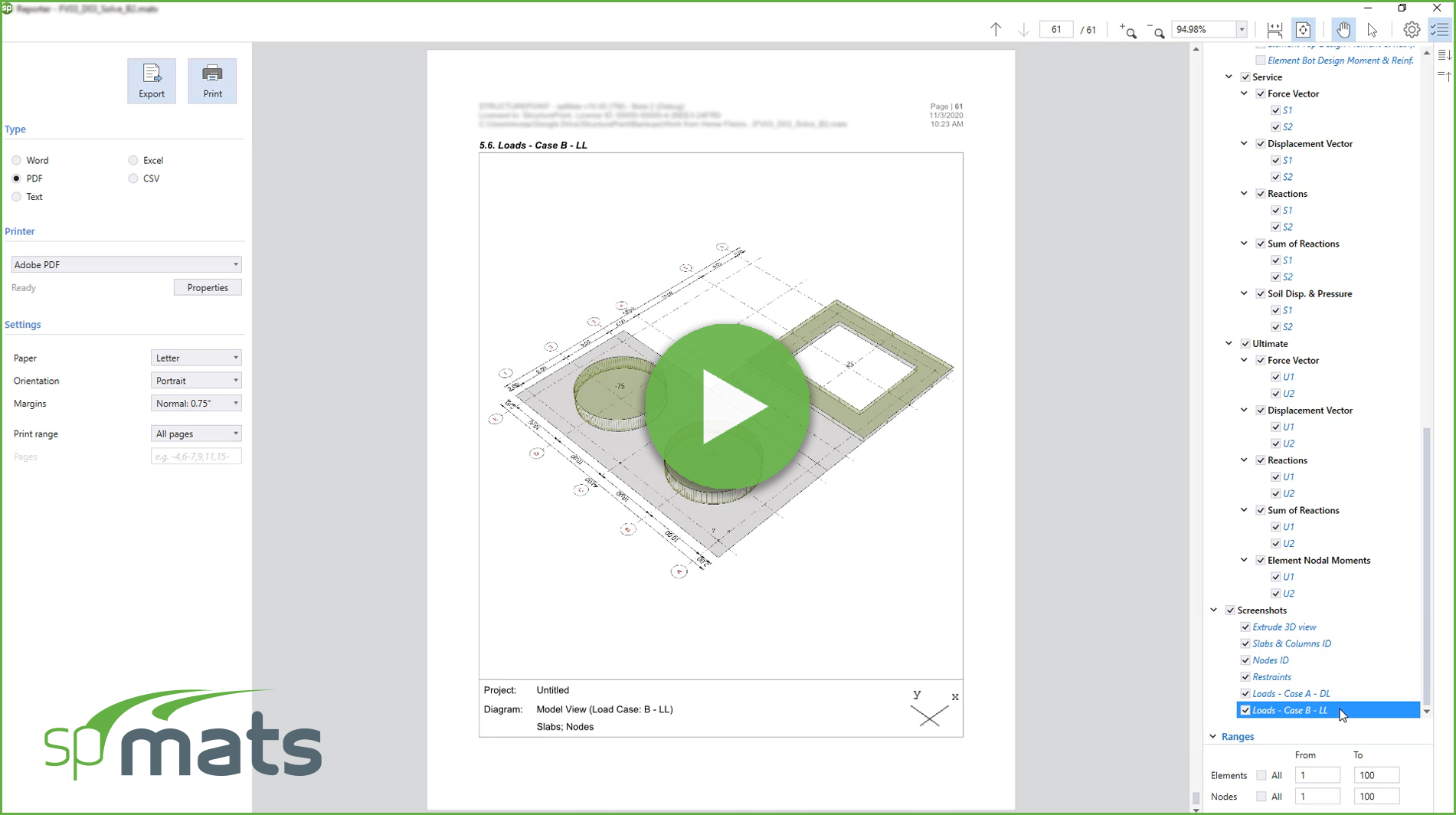
Tutorial video shows how to report and print results using spMats new interface, demonstrates the program settings, and how to import/export inputs and outputs.
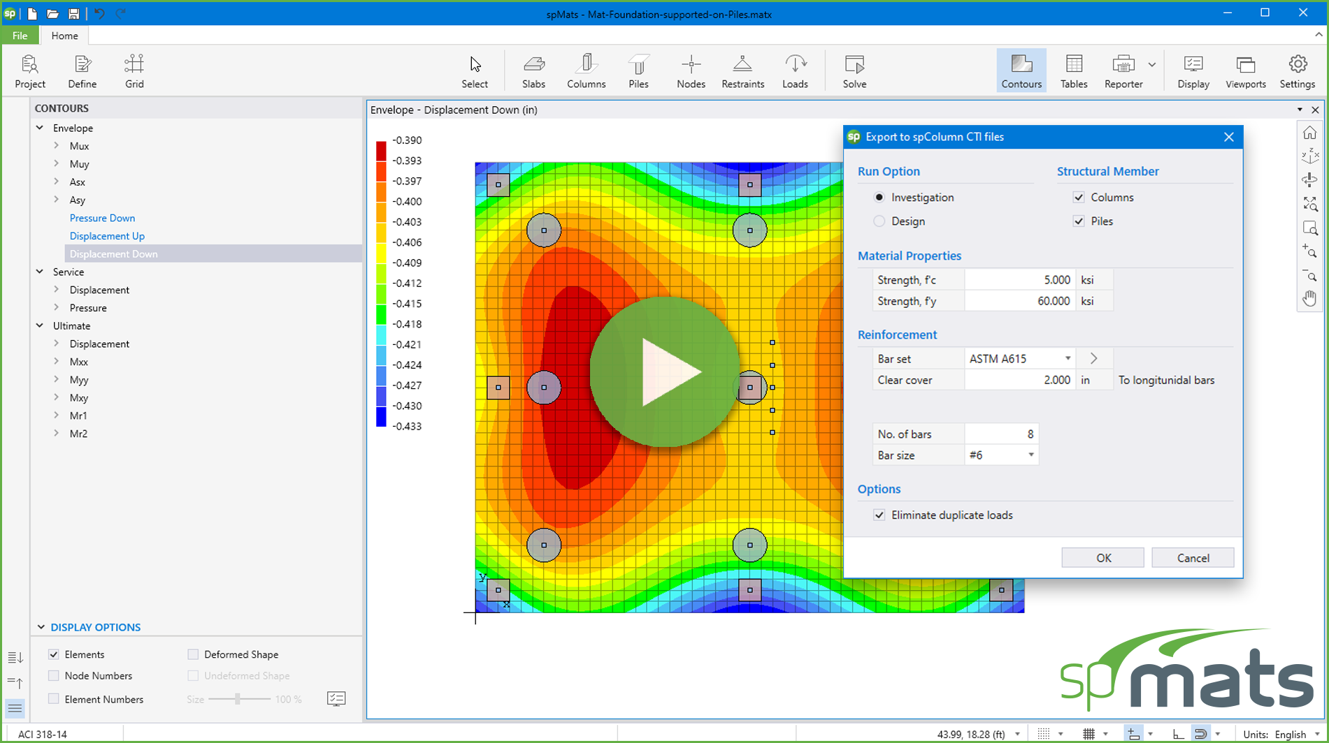
This tutorial video shows how to export column and pile data from spMats model to spColumn.
This tutorial video describes and introduces the major features in spMats to model reinforced concrete foundation systems.
This tutorial video shows how to analyze & design a square spread footing using spMats.
This tutorial video shows how to export column and pile data from spMats v8.50 model to spColumn.
All music from: Bensound.com

.png)
