


.png)
.png)
.png)
.png)
.png)
.png)
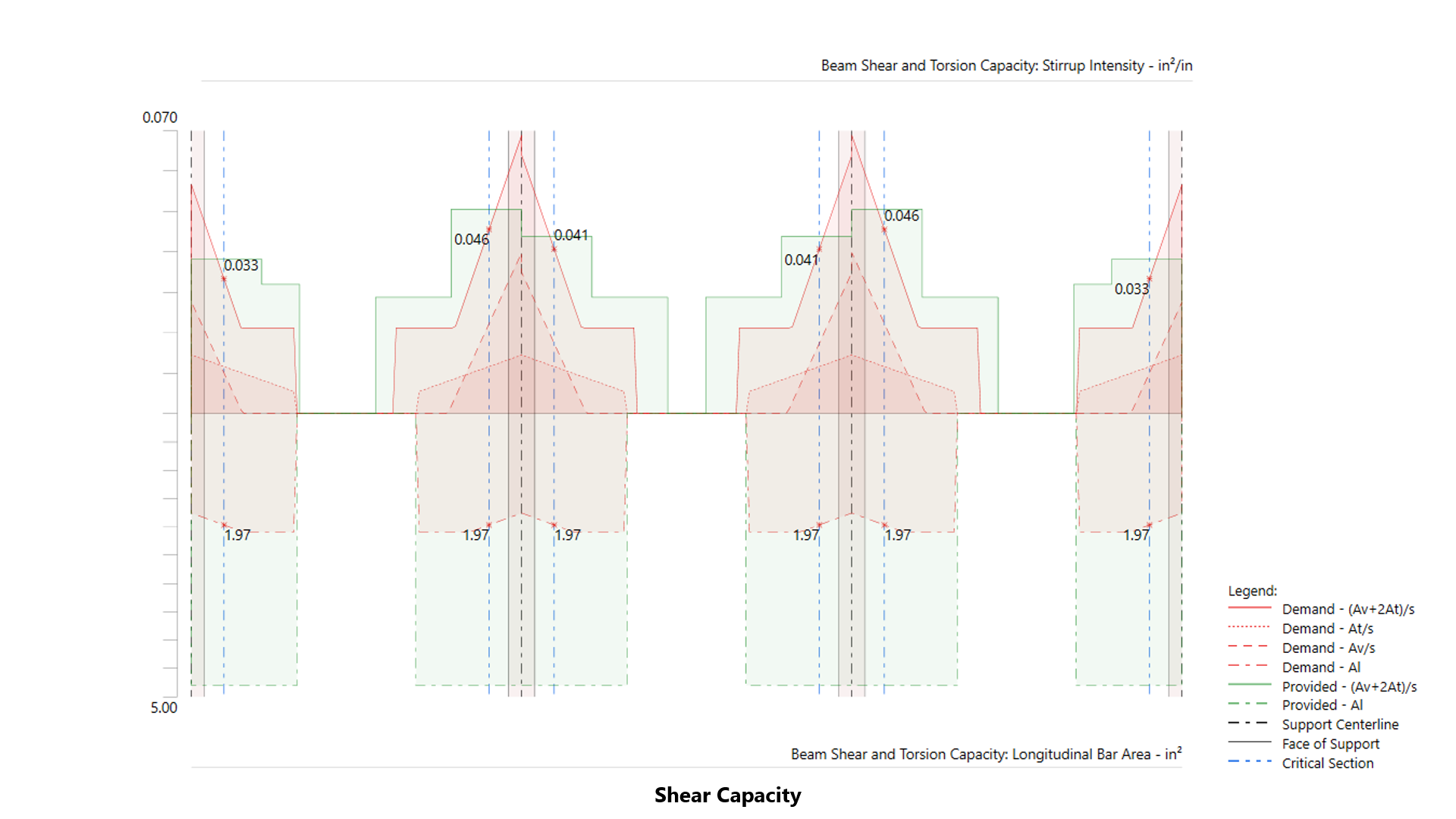
 Shear Calculations Figure.png)
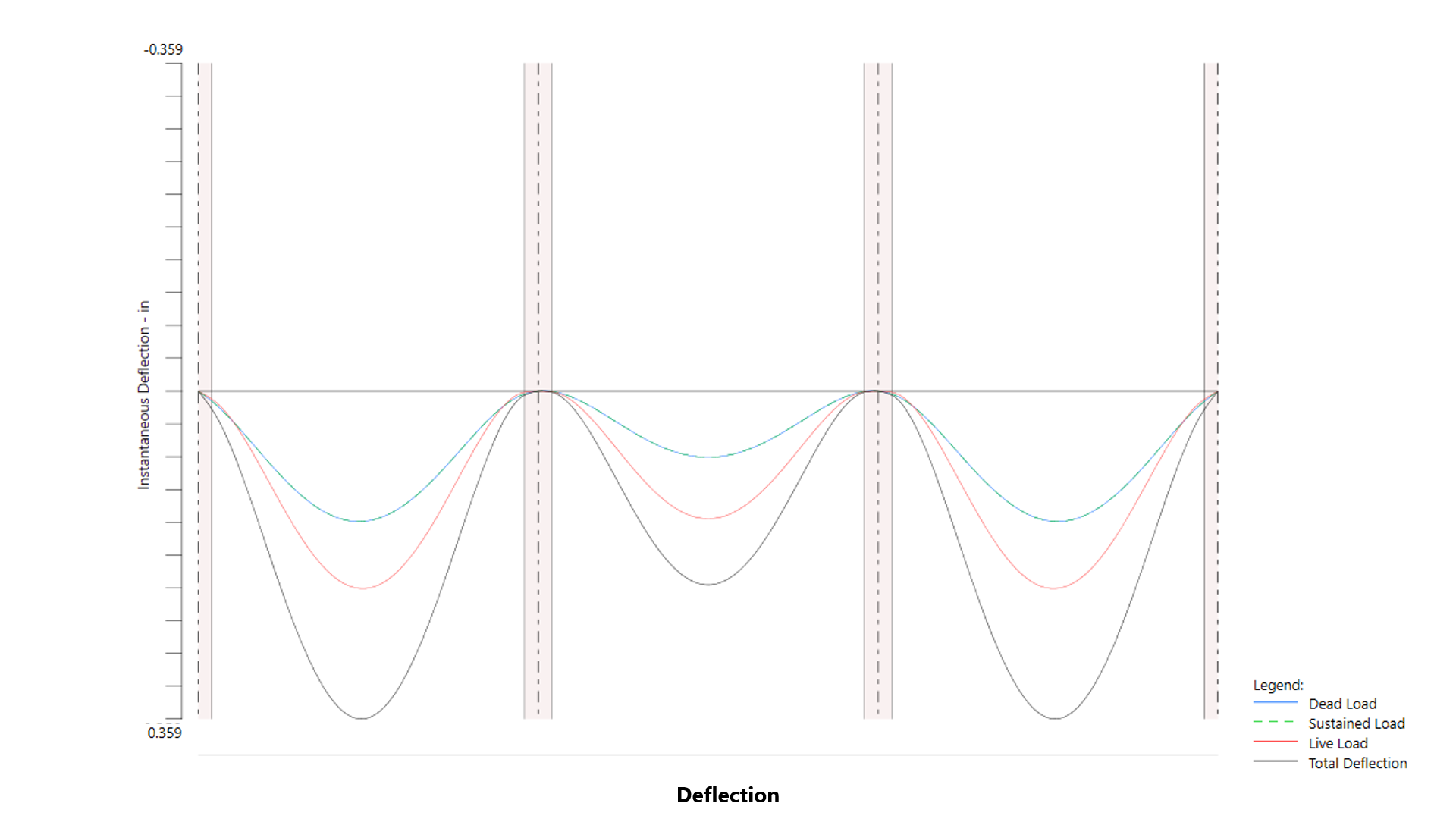
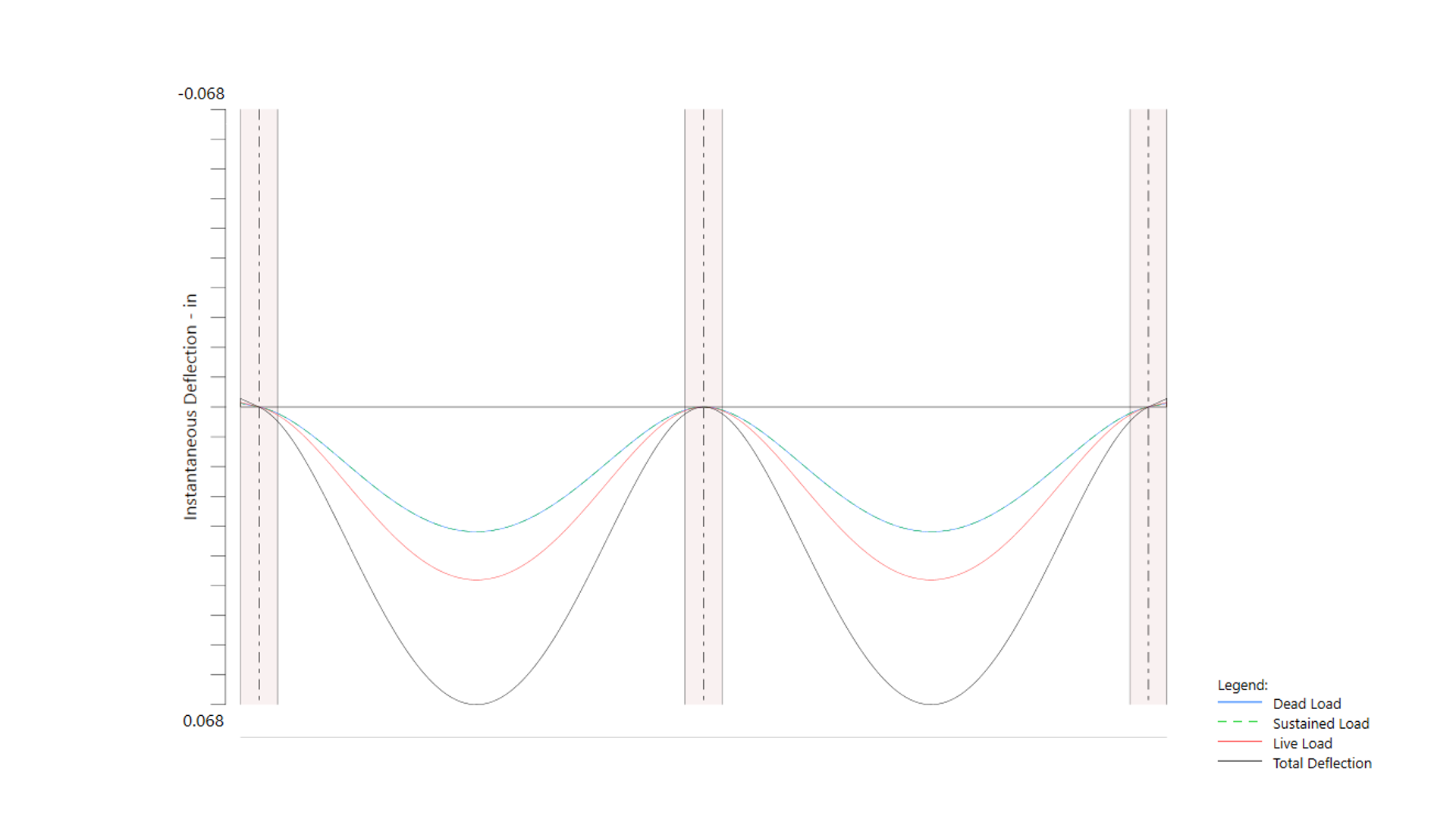
Instantaneous deflections are obtained directly by the program from elastic analysis of the defined system for three load levels. The first corresponds to dead load only, the second corresponds to dead load plus sustained part of live load only, and the third corresponds to dead load plus live load on all spans (total deflection).
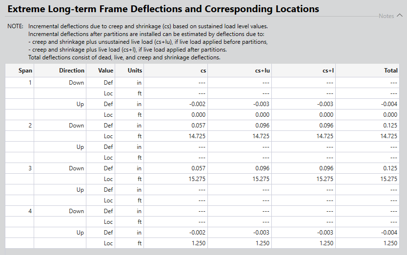
The program estimates additional long-term deflection in structural members due to creep and shrinkage, addressing time-dependent behaviors that affect serviceability.
In structural design, torsion can arise in two forms: equilibrium torsion and compatibility torsion, both of which are effectively addressed in spBeam.
Equilibrium torsion occurs when torsion is essential to maintain the stability of the structural system. For example, in eccentrically loaded members, the torsion must be resisted entirely by the beam to prevent structural failure. spBeam accurately calculates the required torsional reinforcement for such cases, ensuring the member can handle these critical forces without compromise.
On the other hand, compatibility torsion arises from the deformation compatibility between connected structural elements. In these scenarios, the torsion is not essential for stability and can often be redistributed to other parts of the structure. spBeam evaluates whether redistribution is feasible and only recommends torsional reinforcement when necessary. This ensures efficient use of materials and avoids over-reinforcing members where torsion can be relieved through alternative load paths.
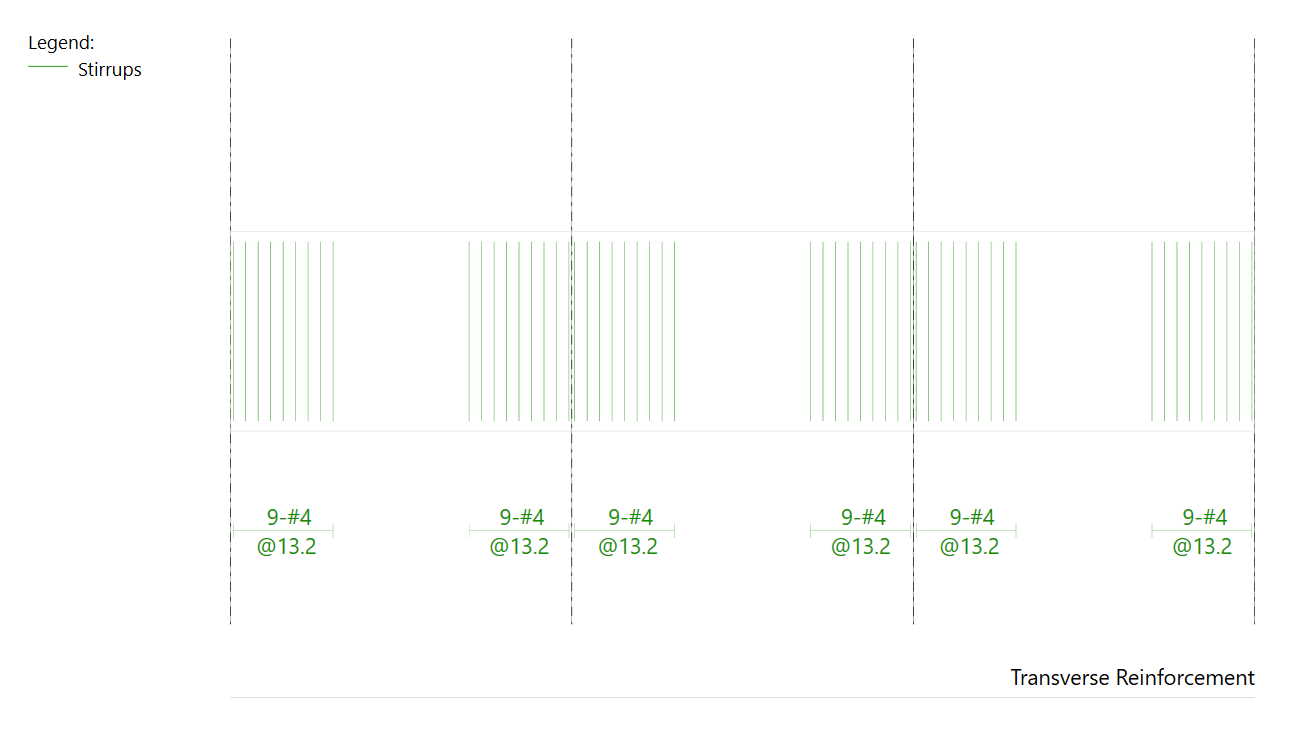
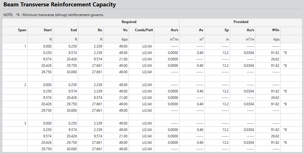
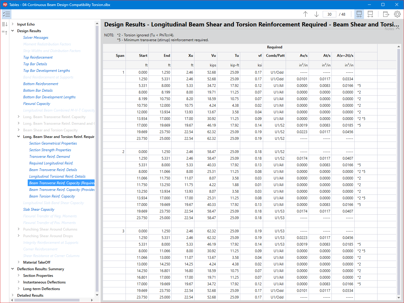
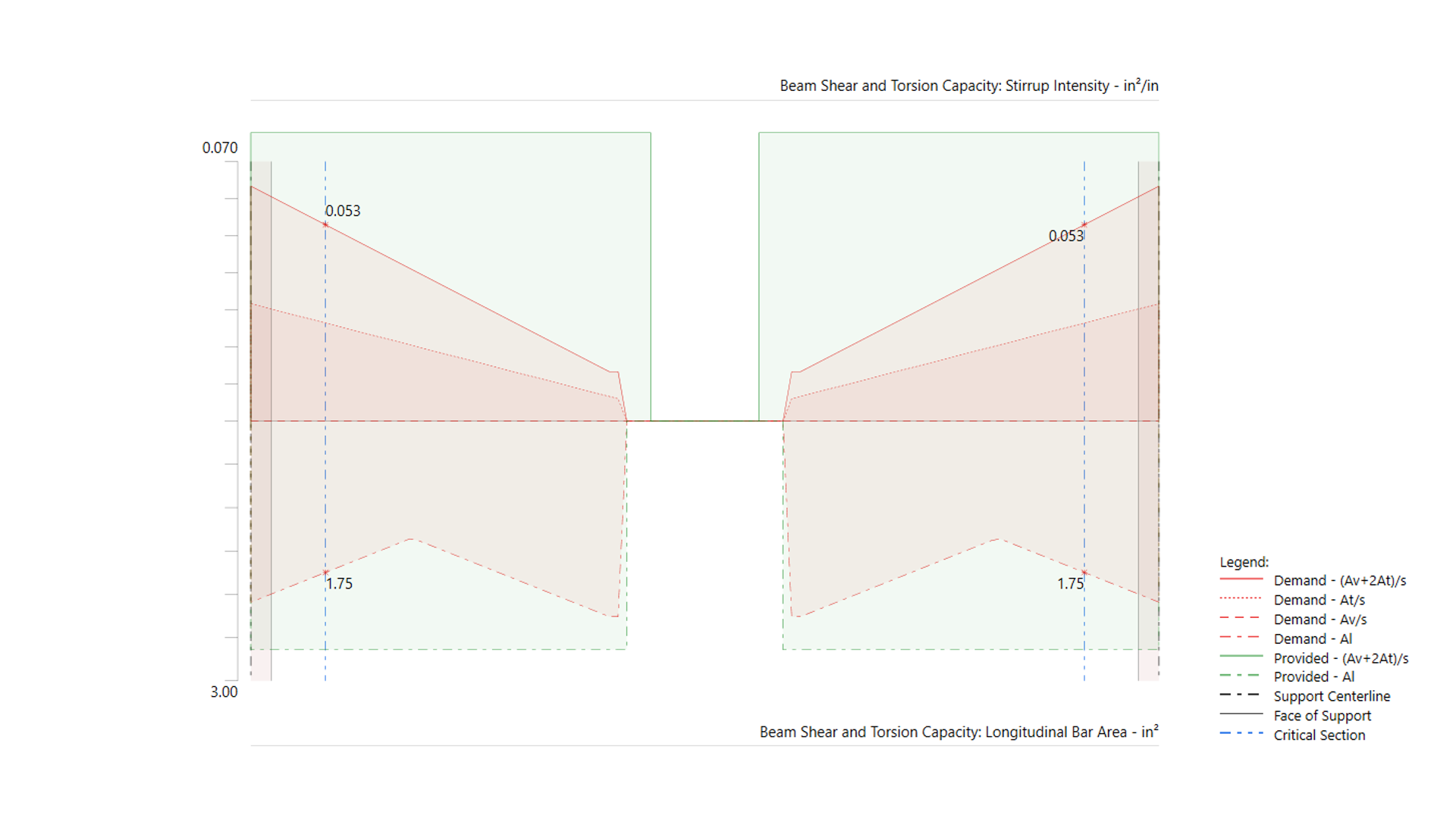
spBeam automatically determines whether torsional reinforcement is required and calculates the necessary amounts of both longitudinal and transverse reinforcement. The program also accounts for interactions between torsion, shear, and bending, ensuring that the combined effects are properly addressed in the design.
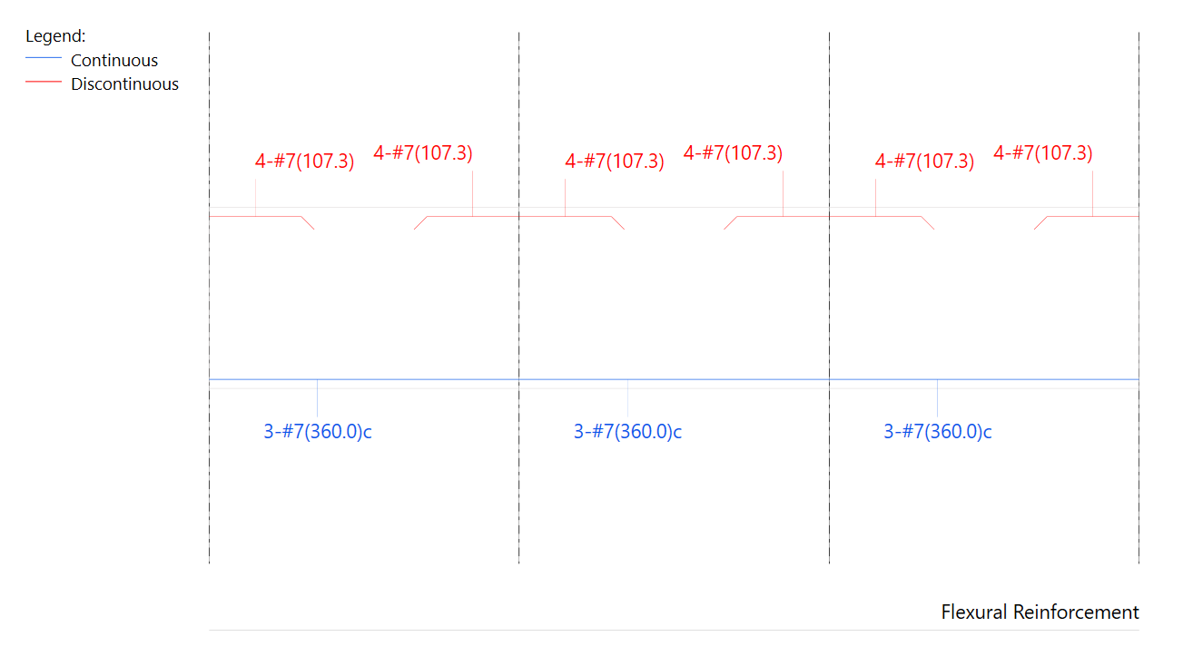
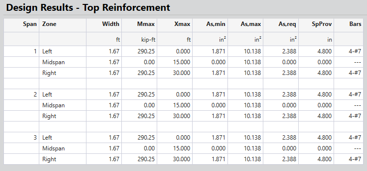
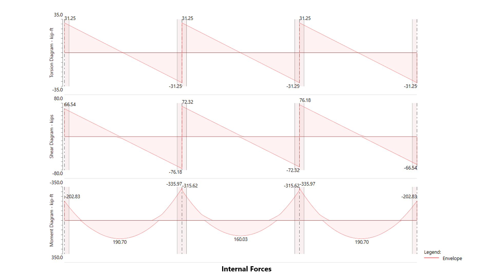
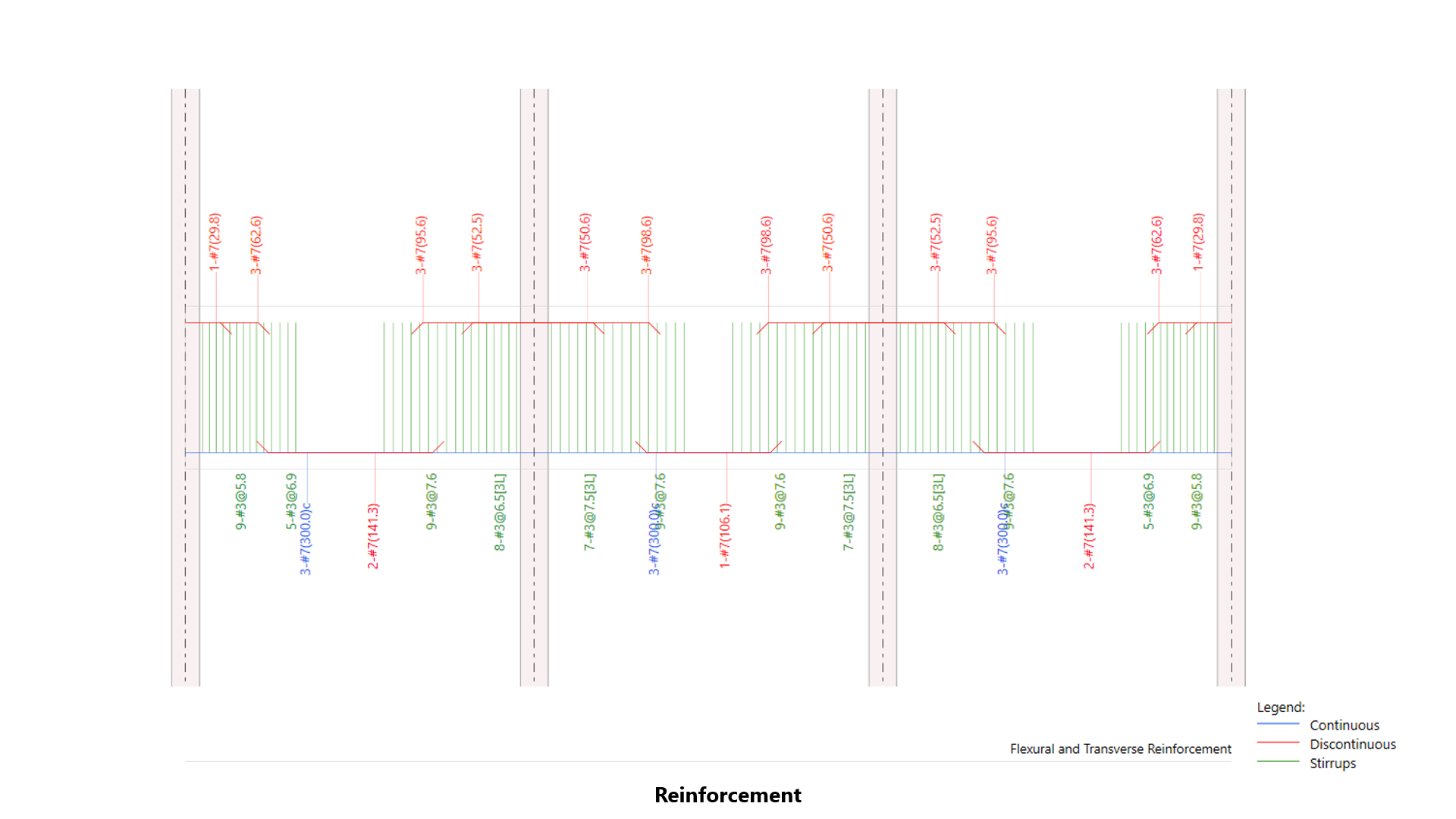
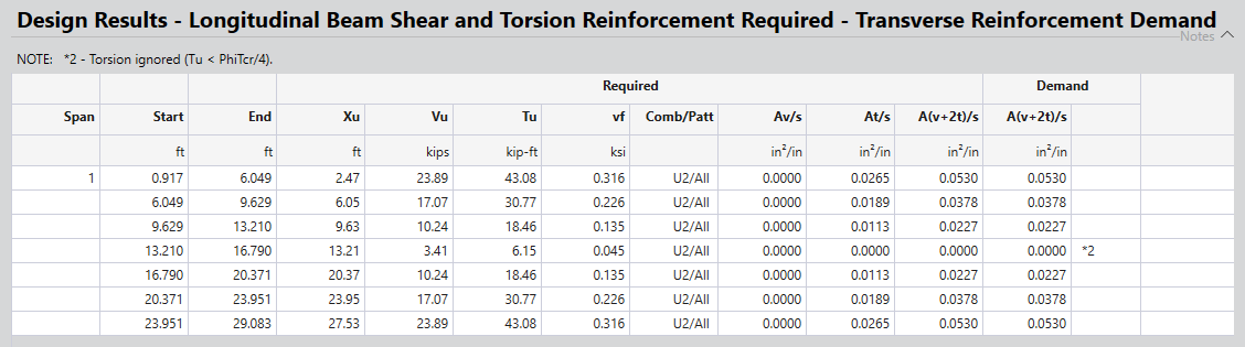
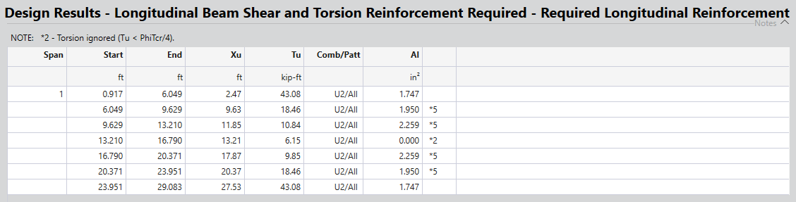
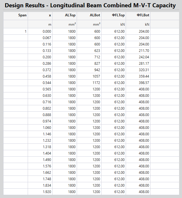
Traditionally, in reinforced concrete beam design, the longitudinal reinforcement for flexure is determined based on the bending moment (M) demand and the transverse reinforcement is determined based on the shear (V) demand. In cases where the beam is subjected to torsion (T) as well, the longitudinal reinforcement for torsion is determined separately and distributed along the perimeter of a cross-section per ACI 318 and CSA A23.3 design provisions. In essence, the required total longitudinal reinforcement is determined by manually combining the required longitudinal reinforcement for bending moment (M) and the required longitudinal reinforcement for torsion (T). Transverse reinforcement shall also need to be determined by considering effects of torsion (T) combined with shear (V) per ACI 318 and CSA A23.3 design provisions.
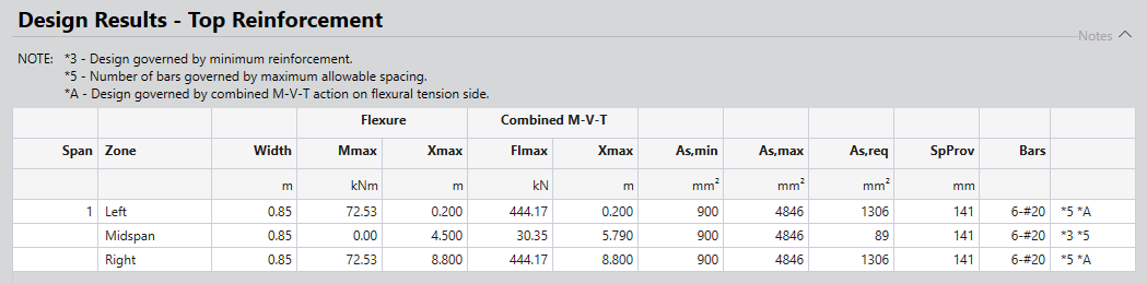
In addition to the traditional approach described above, spBeam Program, also features a Combined M-V-T Reinforcement Design option which was first introduced with CSA A23.3-04 Design Standard. When this option is checked not only torsion (T) effect as in traditional approach but also the shear (V) effect is incorporated with the bending moment (M) effect resulting in the Combined M-V-T for determining the required longitudinal reinforcement. Therefore, this approach is not only more comprehensive for longitudinal reinforcement determination as it incorporates shear (V) as well but also does it all automatically by optimizing structural performance and material efficiency and eliminating the need for manual calculation as in traditional approach. The determination of transverse reinforcement when Combined M-V-T Reinforcement Design option is selected is identical to the traditional approach.
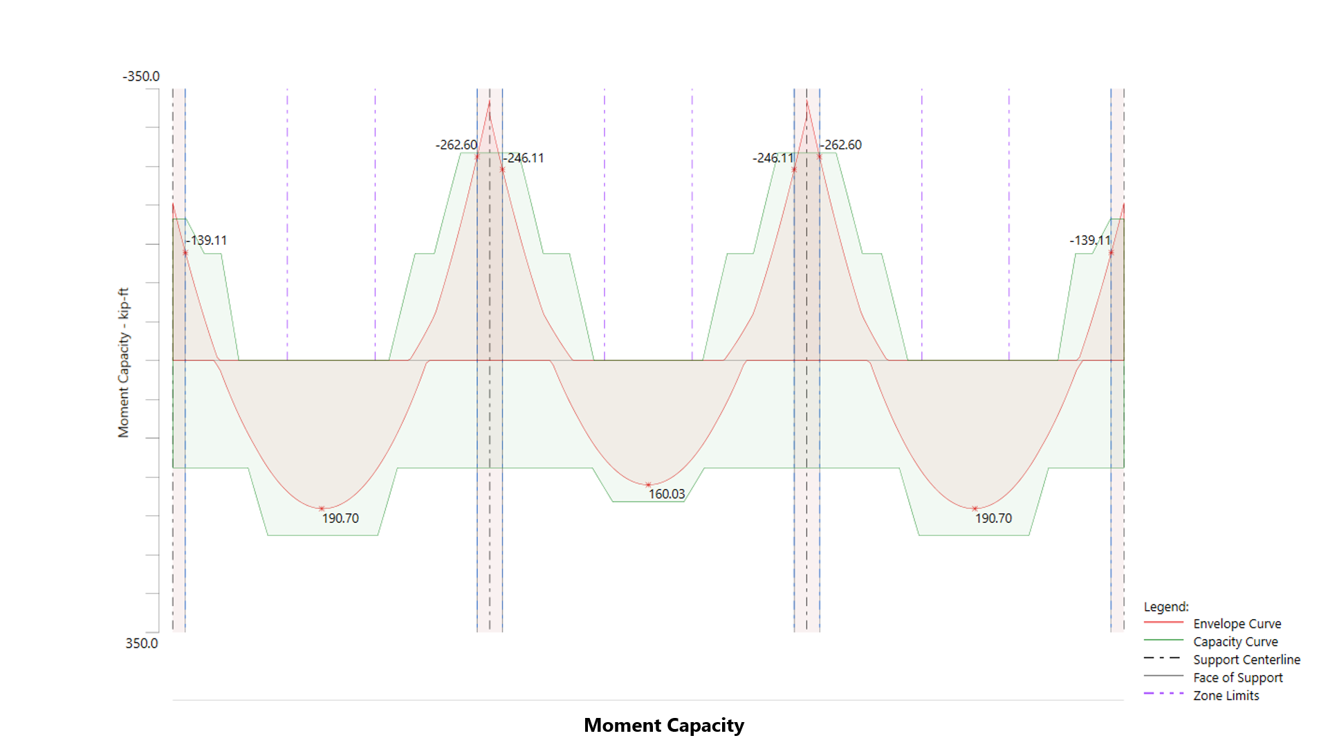
Moment redistribution is a powerful technique that allows for the adjustment of bending moments in continuous beams to optimize reinforcement placement and reduce material usage. Instead of strictly following elastic analysis results, moment redistribution takes advantage of a structure’s plastic capacity, permitting a shift in internal forces that reduces peak negative moments at supports and increases positive moments in spans. This approach leads to more economical reinforcement layouts, minimizing congestion at support locations while maintaining structural stability.
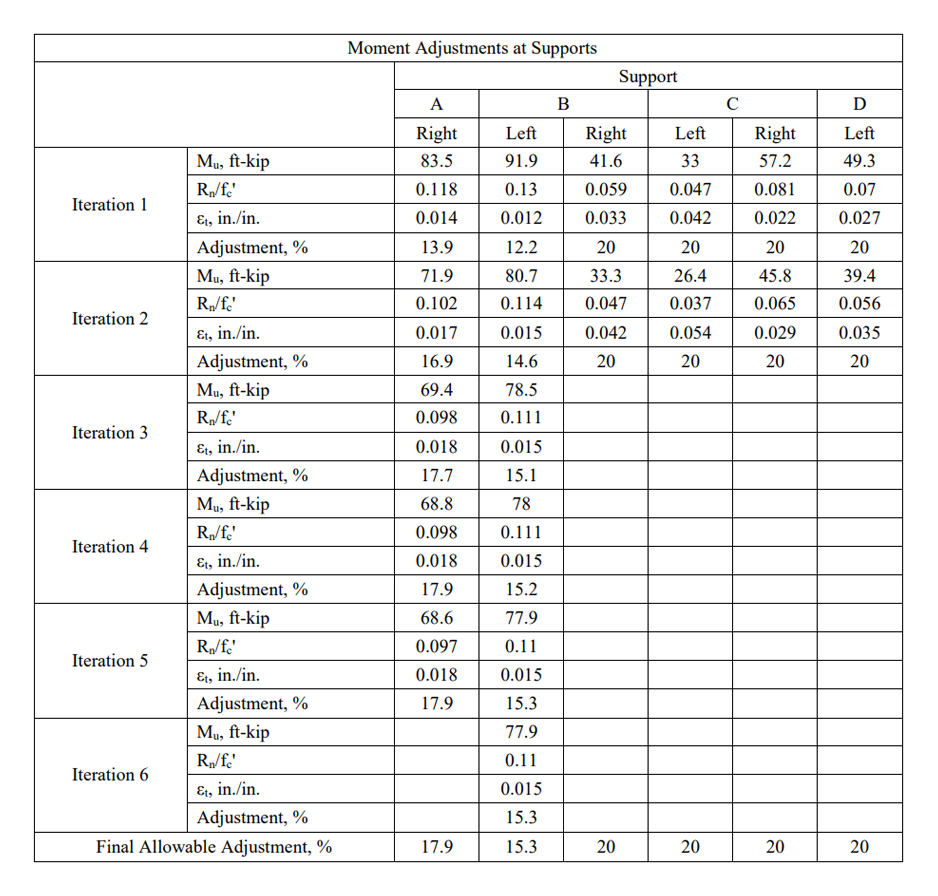
In spBeam, moment redistribution is seamlessly integrated into the design process. The program automatically calculates the allowable reduction in negative moments at supports based on selected code provisions, ensuring compliance with ductility requirements. The software maintains static equilibrium by adjusting bending moments and shear forces along the span, redistributing the loads accordingly. This results in optimized reinforcement detailing that balances structural efficiency and constructability.
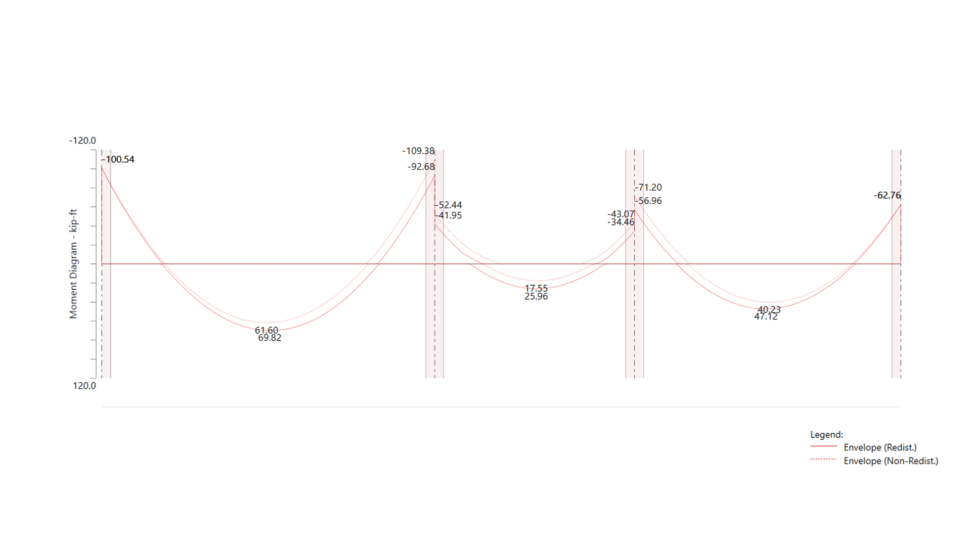
Using spBeam’s moment redistribution feature, engineers can achieve up to 20% reduction in negative moments, significantly decreasing required reinforcement at supports. The program automates the iterative calculations required for redistribution, eliminating tedious manual adjustments and ensuring accurate and code-compliant designs. This feature is particularly beneficial for both new designs and the investigation of existing structures.
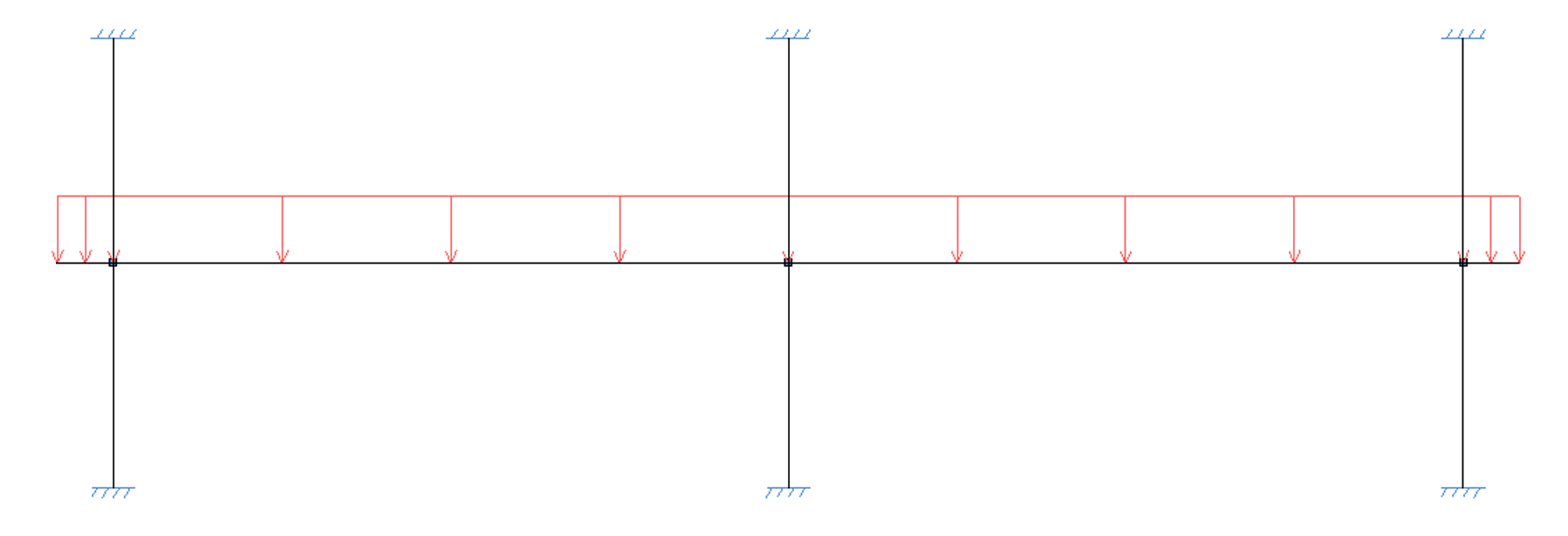
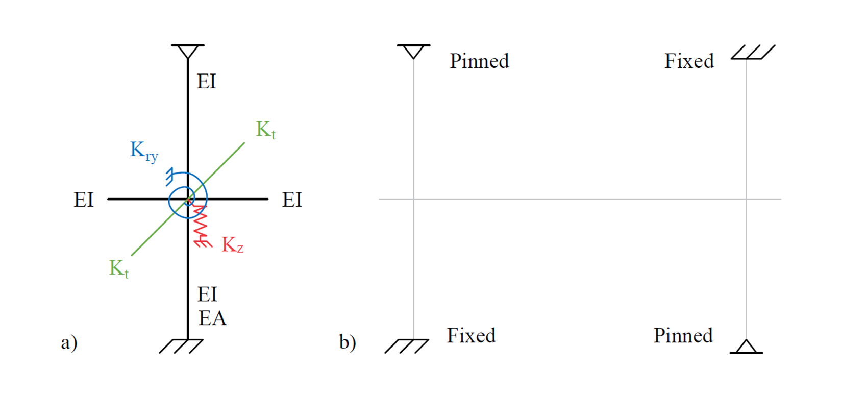
Accurate modeling of support conditions is crucial for ensuring the correct distribution of internal forces, moments, and displacements in reinforced concrete beams and slabs. spBeam provides users with the flexibility to model a variety of support conditions, including fixed, pinned, and spring-supported configurations, allowing for precise control over how structural elements interact with their supports.
Columns and rotational spring restraints can be added to account for partial fixity or flexibility at joints, while the program automatically defaults to pinned conditions if no support elements are defined. Additionally, spBeam includes options to model far-end conditions of columns as either fixed or pinned, further enhancing the adaptability of support definitions to match real-world scenarios.
Support modeling in spBeam also incorporates vertical and rotational spring constants to simulate varying levels of support stiffness, allowing for more refined control over deflections and reactions. These features are particularly beneficial for systems requiring variable support conditions or nonstandard configurations.
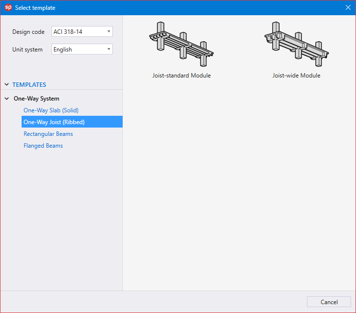
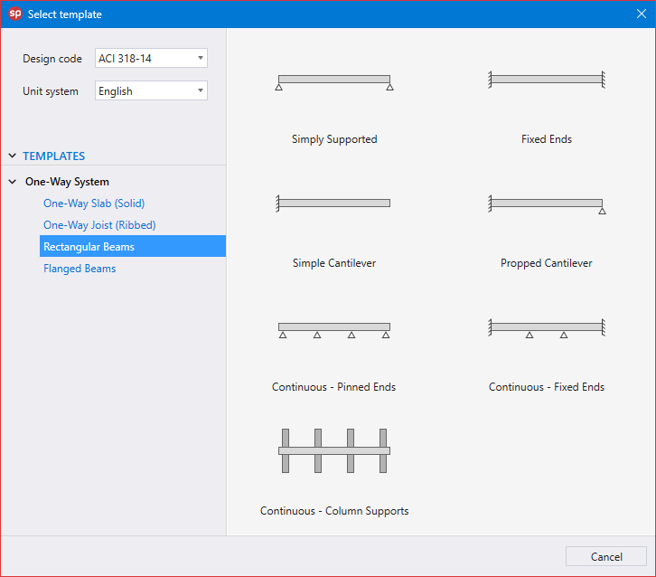
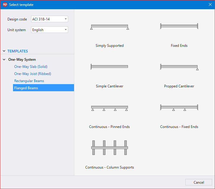
Utilizing Templates is a quick and simple option for new models in spBeam. The user can select from a set of pre-defined templates and edit their properties for simple and quick model generation.
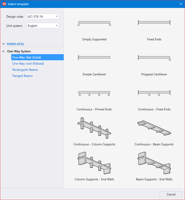
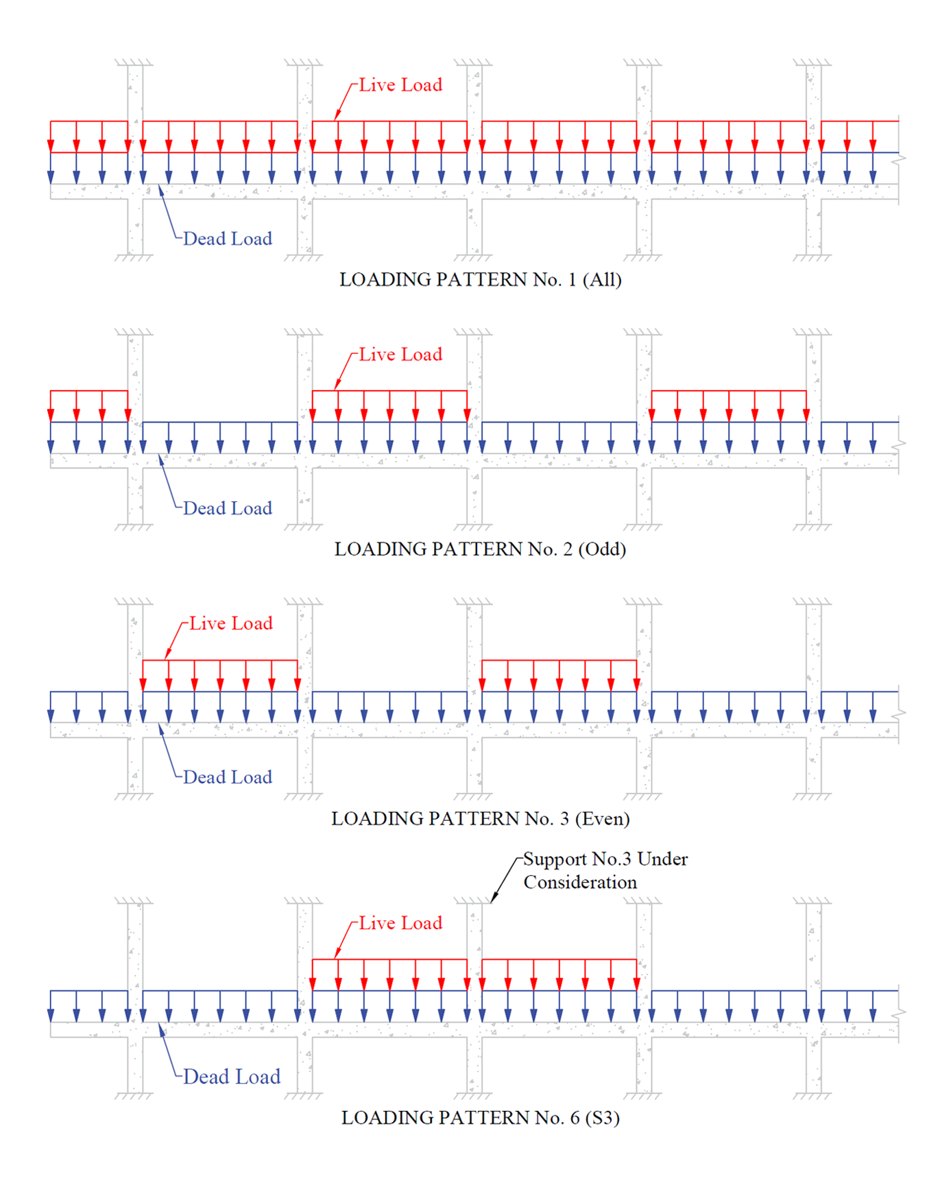
Each template focuses on a particular slab or beam system with a specific loading pattern. The user can edit the geometric dimensions of the system, applied loads, boundary conditions, and material properties. Other system specific options may also be available for some templates.
.png)
Software
spColumn v10.30spMats v10.50spWall v10.20spSlab v10.00spBeam v10.00spFrame v1.50MaintenanceNetwork LicensingDownload & Buy
Buy Now! Download Trial Shopping Cart Pay Invoice