


Two-Way Flat Plate Concrete Slab Floor Analysis and Design (ACI 318-14) (spSlab v10.00)
Author: StructurePoint (SP)
Year: 2025
Pages: 93
This example illustrates the analysis and design of reinforced concrete two-way flat plate system based on the provisions of the American code (ACI 318-14). The Direct Design Method (DDM) and the Equivalent Frame Method (EFM) in ACI 318-14 are used to demonstrate hand calculation procedures. The hand solution from EFM is also used for a detailed comparison with analysis and design results from spSlab v10.00 engineering software program from StructurePoint. Beam action shear, punching shear, Instantaneous deflection, and long-term deflection calculations are also presented in the example.
Two-Way Flat Slab (Drop Panels) Concrete Floor Analysis and Design (ACI 318-14) (spSlab v10.00)
Author: StructurePoint (SP)
Year: 2025
Pages: 113
This example illustrates the analysis and design of reinforced concrete two-way flat slab with drop panels system based on the provisions of the American code (ACI 318-14). The Equivalent Frame Method (EFM) in ACI 318-14 is used to demonstrate the hand calculation procedure. The hand solution from EFM is also used for a detailed comparison with analysis and design results from spSlab v10.00 engineering software program from StructurePoint. Beam action shear, punching shear, Instantaneous deflection, and long-term deflection calculations are also presented in the example.
Two-Way Concrete Floor Slab with Beams System Analysis and Design (ACI 318-14) (spSlab v10.00)
Author: StructurePoint (SP)
Year: 2025
Pages: 98
This example illustrates the analysis and design of reinforced concrete two-way floor slab with beams based on the provisions of the American code (ACI 318-14). The Equivalent Frame Method (EFM) in ACI 318-14 is used to demonstrate the hand calculation procedure. The hand solution from EFM is also used for a detailed comparison with analysis and design results from spSlab v10.00 engineering software program from StructurePoint. Beam action shear, punching shear, instantaneous deflection, and long-term deflection calculations are also presented in the example.
Two-Way Joist Concrete Slab Floor (Waffle Slab) System Analysis and Design (ACI 318-14) (spSlab v10.00)
Author: StructurePoint (SP)
Year: 2025
Pages: 116
This example illustrates the analysis and design of reinforced concrete two-way joist concrete waffle slab based on the provisions of the American code (ACI 318-14). The Equivalent Frame Method (EFM) in ACI 318-14 is used to demonstrate the hand calculation procedure. The hand solution from EFM is also used for a detailed comparison with analysis and design results from spSlab v10.00 engineering software program from StructurePoint. Beam action shear, punching shear, instantaneous deflection, and long-term deflection calculations are also presented in the example.
Two-Way Flat Plate Concrete Slab Floor Analysis and Design (ACI 318-14) (spSlab v5.50)
Author: StructurePoint (SP)
Year: 2023
Pages: 88
This example illustrates the analysis and design of reinforced concrete two-way flat plate system based on the provisions of the American code (ACI 318-14). The Direct Design Method (DDM) and the Equivalent Frame Method (EFM) in ACI 318-14 are used to demonstrate hand calculation procedures. The hand solution from EFM is also used for a detailed comparison with analysis and design results from spSlab v5.50 engineering software program from StructurePoint. Beam action shear, punching shear, Instantaneous deflection, and long-term deflection calculations are also presented in the example.
Two-Way Flat Slab (Drop Panels) Concrete Floor Analysis and Design (ACI 318-14) (spSlab v5.50)
Author: StructurePoint (SP)
Year: 2023
Pages: 108
This example illustrates the analysis and design of reinforced concrete two-way flat slab with drop panels system based on the provisions of the American code (ACI 318-14). The Equivalent Frame Method (EFM) in ACI 318-14 is used to demonstrate the hand calculation procedure. The hand solution from EFM is also used for a detailed comparison with analysis and design results from spSlab v5.50 engineering software program from StructurePoint. Beam action shear, punching shear, Instantaneous deflection, and long-term deflection calculations are also presented in the example.
Two-Way Concrete Floor Slab with Beams System Analysis and Design (ACI 318-14) (spSlab v5.50)
Author: StructurePoint (SP)
Year: 2024
Pages: 93
This example illustrates the analysis and design of reinforced concrete two-way floor slab with beams based on the provisions of the American code (ACI 318-14). The Equivalent Frame Method (EFM) in ACI 318-14 is used to demonstrate the hand calculation procedure. The hand solution from EFM is also used for a detailed comparison with analysis and design results from spSlab v5.50 engineering software program from StructurePoint. Beam action shear, punching shear, instantaneous deflection, and long-term deflection calculations are also presented in the example.
Two-Way Joist Concrete Slab Floor (Waffle Slab) System Analysis and Design (ACI 318-14) (spSlab v5.50)
Author: StructurePoint (SP)
Year: 2024
Pages: 110
This example illustrates the analysis and design of reinforced concrete two-way joist concrete waffle slab based on the provisions of the American code (ACI 318-14). The Equivalent Frame Method (EFM) in ACI 318-14 is used to demonstrate the hand calculation procedure. The hand solution from EFM is also used for a detailed comparison with analysis and design results from spSlab v5.50 engineering software program from StructurePoint. Beam action shear, punching shear, instantaneous deflection, and long-term deflection calculations are also presented in the example.
Two-Way Flat Plate Concrete Slab Floor Analysis and Design (ACI 318-14) (spSlab v5.00)
Format: (PDF)
Author: StructurePoint (SP)
Year: 2017
Pages: 64
The two analysis procedures shown in ACI 318-14: Direct Design Method (DDM) and the Equivalent Frame Method (EFM) are illustrated in detail to analyze and design two-way flat plate system. The hand solution from EFM is also used for a detailed comparison with the analysis and design results of the engineering software program spSlab including detailed deflection calculations.
Two-Way Flat Slab (Drop Panels) Concrete Floor Analysis and Design (ACI 318-14) (spSlab v5.00)
Format: (PDF)
Author: StructurePoint (SP)
Year: 2017
Pages: 60
The Equivalent Frame Method (EFM) presented in ACI 318-14 is illustrated in detail in this example to analyze and design two-way flat slab with drop panels system. The EFM solution is also used for a detailed comparison with the analysis and design results of the engineering software program spSlab. This example highlights code based selection of drop panel dimensions, analysis process of non-prismatic slab with drop panels, the crucial role of drop panels in resisting two-way shear at columns, and detailed deflection calculations.
Two-Way Concrete Slab on Beams Floor Analysis and Design (ACI 318-14) (spSlab v5.00)
Format: (PDF)
Author: StructurePoint (SP)
Year: 2017
Pages: 49
The Equivalent Frame Method (EFM) presented in ACI 318-14 is illustrated in detail in this example to analyze and design two-way floor slab with beams. The EFM solution is also used for a detailed comparison with the analysis and design results of the engineering software program spSlab. This example highlights the slab interaction with the longitudinal and transverse beams and their effect on the system flexural and torsional stiffness including detailed deflection calculations.
Two-Way Joist (Waffle Slab) Concrete Floor System Analysis and Design (ACI 318-14) (spSlab v5.00)
Format: (PDF)
Author: StructurePoint (SP)
Year: 2017
Pages: 86
The Equivalent Frame Method (EFM) presented in ACI 318-14 is illustrated to analyze and design two-way waffle slab system. The EFM solution is also used for a detailed comparison with the analysis and design results of the engineering software program spSlab. This example highlights code based selection of rib and drop head dimensions, analysis process of non-prismatic slab due to the presence of longitudinal and transverse ribs and drop heads, two-way shear check for waffle slabs, and detailed deflection calculations.
Shear Strength of Concrete Slabs with Openings (ACI 318-14)
Format: (PDF)
Author: StructurePoint (SP)
Year: 2020
Pages: 17
Openings in concrete floor slab systems can have a significant effect on one-way and two-way shear strength of the slab. This effect is illustrated in this example for a concrete flat plate floor system. In this example, a hypothetical floor opening is placed next to a column to simulate an opening needed for cable tray system in a data center building housing server racks. To demonstrate the opening effects, one-way and two-way shear checks are conducted for two cases: slab without openings, and slab with opening.
Two-way (Punching) Shear Calculations for Concrete Slab Supported by Circular Columns
Format: (PDF)
Author: StructurePoint (SP)
Year: 2019
Pages: 17
Perform the two-way (punching) shear calculations around the exterior and interior circular columns supporting a two-way flat plate concrete slab. These calculations are widely published in text books for square and rectangular shapes but rarely are discussed in detail for circular columns or column capitals. This design example provides step-by-step hand-calculations and compares various ACI methodologies to determine the critical shear perimeter of circular columns.
Role of GammaF in Two-way Slab Punching Shear Calculations in ACI 318
Format: (PDF)
Author: StructurePoint (SP)
Year: 2019
Pages: 16
The modification of the GammaF as permitted by ACI 318-14 & 318-19 enables a satisfactory design to replace costly alternatives to limit punching shear impact on concrete floor thickness. GammaF modification is an important feature in spSlab and can be used as a tool that offers the flexibility to transfer unbalanced moment by optimizing the proportion by which resistance is provided by the combination of shear and flexure.
Two-Way Flat Plate Concrete Slab Floor Analysis and Design (CSA A23.3-14)
Format: (PDF)
Author: StructurePoint (SP)
Year: 2018
Pages: 67
The two analysis procedures shown in CSA A23.3-14: Direct Design Method (DDM) and the Elastic Frame Method (EFM) are illustrated in detail to analyze and design two-way flat plate system. The hand solution from EFM is also used for a detailed comparison with the analysis and design results of the engineering software program spSlab including detailed deflection calculations.
Two-Way Flat Slab (Drop Panels) Concrete Floor Analysis and Design (CSA A23.3-14)
Format: (PDF)
Author: StructurePoint (SP)
Year: 2018
Pages: 82
The Elastic Frame Method (EFM) presented in CSA A23.3-14 is illustrated in detail in this example to analyze and design two-way flat slab with drop panels system. The EFM solution is also used for a detailed comparison with the analysis and design results of the engineering software program spSlab. This example highlights code based selection of drop panel dimensions, analysis process of non-prismatic slab with drop panels, the crucial role of drop panels in resisting two-way shear at columns, and detailed deflection calculations.
Two-Way Concrete Slab on Beams Floor Analysis and Design (CSA A23.3-14)
Format: (PDF)
Author: StructurePoint (SP)
Year: 2018
Pages: 70
The Elastic Frame Method (EFM) presented in CSA A23.3-14 is illustrated in detail in this example to analyze and design two-way floor slab with beams. The EFM solution is also used for a detailed comparison with the analysis and design results of the engineering software program spSlab. This example highlights the slab interaction with the longitudinal and transverse beams and their effect on the system flexural and torsional stiffness including detailed deflection calculations.
Two-Way Flat Plate Concrete Floor System Analysis and Design (CAC Design Handbook)
Format: (PDF)
Author: StructurePoint (SP)
Year: 2019
Pages: 57
The Elastic Frame Method (EFM) shown in CSA A23.3-14 is illustrated in detail to analyze and design two-way flat plate system. The most commonly used example from CAC design handbook is being selected as a reference. The hand solution from EFM is used for a detailed comparison with the analysis and design results of the engineering software program spSlab.
Two-Way Flat Slab (Concrete Floor System with Drop Panels) Analysis and Design (CAC Design Handbook)
Format: (PDF)
Author: StructurePoint (SP)
Year: 2019
Pages: 73
The Elastic Frame Method (EFM) presented in CSA A23.3-14 is illustrated in detail in this example to analyze and design two-way flat slab with drop panels system. The most commonly used example from CAC design handbook is being selected as a reference. The EFM solution is also used for a detailed comparison with the analysis and design results of the engineering software program spSlab. This example highlights code based selection of drop panel dimensions, analysis process of non-prismatic slab with drop panels, the crucial role of drop panels in resisting two-way shear at columns, and detailed deflection calculations.
Two-Way Slab with Beams Design and Detailing (CAC Design Handbook)
Format: (PDF)
Author: StructurePoint (SP)
Year: 2019
Pages: 68
The Elastic Frame Method (EFM) shown in CSA A23.3-14 is illustrated in detail to analyze and design two-way slab on beams system. The most commonly used example from CAC design handbook is being selected as a reference. The hand solution from EFM is used for a detailed comparison with the analysis and design results of the engineering software program spSlab.
Two-Way Concrete Floor with Slab Bands - Transverse Bands Analysis and Design (CAC Design Handbook)
Format: (PDF)
Author: StructurePoint (SP)
Year: 2021
Pages: 71
This example will examine two-way floors with slab bands systems. The analysis is performed on design strips perpendicular to the slab bands (Transverse Bands). The use of flat plate system will be checked first. If the use of flat plate is not adequate, the use of a slab system with slab bands will be investigated. Elastic Frame Method (EFM) is used in the hand solution, then the results are used for a comprehensive comparison with results from the Reference using the Direct Design Method (DDM). The EFM hand solution results are further compared with the output from the engineering software program spSlab. A table comparing the three two-way slab analysis methods is provided at the end of this document.
Two-Way Concrete Floor with Slab Bands - Longitudinal Bands Analysis and Design (CAC Design Handbook)
Format: (PDF)
Author: StructurePoint (SP)
Year: 2021
Pages: 70
This example will examine two-way floors with slab bands systems. The analysis is performed on design strips parallel to the slab bands (Longitudinal Bands). The use of flat plate system will be checked first. If the use of flat plate is not adequate, the use of a slab system with slab bands will be investigated. Elastic Frame Method (EFM) is used in the hand solution, then the results are used for a comprehensive comparison with results from the Reference using the Direct Design Method (DDM). The EFM hand solution results are further compared with the output from the engineering software program spSlab. A table comparing the three two-way slab analysis methods is provided at the end of this document.
Shear Strength of Concrete Slabs with Openings (CSA A23.3-14)
Format: (PDF)
Author: StructurePoint (SP)
Year: 2021
Pages: 17
Openings in concrete floor slab systems can have a significant effect on one-way and two-way shear strength of the slab. This effect is illustrated in this example for a concrete flat plate floor system using CSA A23.3-14 provisions. In this example, a hypothetical floor opening is placed next to a column to simulate an opening needed for cable tray system in a data center building housing server racks. To demonstrate the opening effects, one-way and two-way shear checks are conducted for two cases: slab without openings, and slab with opening.
Punching Shear Calculations for Concrete Slab Supported by Circular Columns (CSA A23.3)
Format: (PDF)
Author: StructurePoint (SP)
Year: 2021
Pages: 20
Perform the two-way (punching) shear calculations around the exterior and interior circular columns supporting a two-way flat plate concrete slab. These calculations are widely published in text books for square and rectangular shapes but rarely are discussed in detail for circular columns or column capitals. This design example provides step-by-step hand-calculations and compares various CSA methodologies to determine the critical shear perimeter of circular columns.
Role of GammaF in Two-way Slab Punching Shear Calculations in CSA A23.3
Format: (PDF)
Author: StructurePoint (SP)
Year: 2019
Pages: 16
The use of the GammaF in CSA A23.3-14 & 19 standards is integral to two-way (punching) shear resistance and sets limits to punching shear resistance through direct shear and moment transfer by flexure. GammaF modification is an important feature in spSlab and can be used as a tool that offers the flexibility to transfer unbalanced moment by optimizing the proportion by which resistance is provided by the combination of shear and flexure.
Simply Supported Reinforced Concrete Beam Analysis and Design (ACI 318-14) (spBeam v10.00)
Author: StructurePoint (SP)
Year: 2025
Pages: 36
This example demonstrates the analysis and design of a rectangular simply supported reinforced concrete beam using ACI 318-14 provisions. Steps of the structural analysis, flexural design, shear design, and deflection checks are presented. The results of hand calculations are compared with the numerical analysis results obtained from spBeam v10.00 engineering software program by StructurePoint.
Simply Supported Reinforced Concrete Beam Analysis and Design (ACI 318-14) (spBeam v5.50)
Author: StructurePoint (SP)
Year: 2021
Pages: 33
This example demonstrates the analysis and design of a rectangular simply supported reinforced concrete beam using ACI 318-14 provisions. Steps of the structural analysis, flexural design, shear design, and deflection checks are presented. The results of hand calculations are compared with the numerical analysis results obtained from spBeam v5.50 engineering software program by StructurePoint.
Reinforced Concrete Cantilever Beam Analysis and Design (ACI 318-14) (spBeam v10.00)
Author: StructurePoint (SP)
Year: 2025
Pages: 38
This example demonstrates the analysis and design of a rectangular reinforced concrete cantilever beam using ACI 318-14 provisions. Steps of the structural analysis, flexural design, shear design, and deflection checks are presented. The results of hand calculations are compared with the numerical analysis results obtained from the spBeam v10.00 engineering software program by StructurePoint.
Reinforced Concrete Cantilever Beam Analysis and Design (ACI 318-14) (spBeam v5.50)
Author: StructurePoint (SP)
Year: 2021
Pages: 34
This example demonstrates the analysis and design of a rectangular reinforced concrete cantilever beam using ACI 318-14 provisions. Steps of the structural analysis, flexural design, shear design, and deflection checks are presented. The results of hand calculations are compared with the numerical analysis results obtained from the spBeam v5.50 engineering software program by StructurePoint.
Doubly Reinforced Concrete Beam Design (ACI 318-14) (spBeam v10.00)
Author: StructurePoint (SP)
Year: 2025
Pages: 19
The design of doubly reinforced concrete beam with compression reinforcement is shown in this example. The hand and reference solutions are used for a detailed comparison with results obtained from spBeam v10.00 engineering software program by StructurePoint.
Doubly Reinforced Concrete Beam Design (ACI 318-14) (spBeam v5.50)
Format: (PDF)
Author: StructurePoint (SP)
Year: 2020
Pages: 17
The design of doubly reinforced concrete beam with compression reinforcement is shown in this example. The hand and reference solutions are used for a detailed comparison with results obtained from spBeam v5.50 engineering software program by StructurePoint.
Equilibrium Torsion in Beams (ACI 318-14) (spBeam v10.00)
Author: StructurePoint (SP)
Year: 2026
Pages: 37
The equilibrium torsion analysis and design of a rectangular reinforced concrete cantilever beam in accordance with ACI 318-14 provisions is presented in this example. The hand and reference solutions are used for a detailed comparison with results obtained from spBeam v10.00 engineering software program by StructurePoint.

Reinforced Concrete Continuous Beam Analysis and Design (ACI 318-14)
Format: (PDF)
Author: StructurePoint (SP)
Year: 2018
Pages: 44
A structural reinforced concrete continuous beam at an intermediate building floor is analyzed and designed (Including structural analysis, flexural design, shear design, and deflection checks) and the results of hand calculations are then compared with numerical analysis results obtained from the spBeam engineering software program. Additionally, different boundary conditions are selected to demonstrate and explore in detail the actual interaction between beams and supporting members. Similar evaluation is performed using computer software to reflect recommended modeling procedures in spBeam to obtain the most accurate results.

One-Way Wide Module (Skip Joist) Concrete Floor System Design (ACI 318-14) (spBeam v10.00)
Author: StructurePoint (SP)
Year: 2025
Pages: 117
This example illustrates the analysis and design of one-way slab, one-way joist, interior girder, and exterior girder in a one-way wide module (skip joist) floor system. The hand solution is used for a detailed comparison with analysis and design results from spBeam v10.00 engineering software program from StructurePoint. Load determination, flexural design, shear design, torsion design, and deflection calculations are presented in this example.
One-Way Wide Module (Skip Joist) Concrete Floor System Design (ACI 318-14) (spBeam v5.50)
Author: StructurePoint (SP)
Year: 2023
Pages: 109
This example illustrates the analysis and design of one-way slab, one-way joist, interior girder, and exterior girder in a one-way wide module (skip joist) floor system. The hand solution is used for a detailed comparison with analysis and design results from spBeam v5.50 engineering software program from StructurePoint. Load determination, flexural design, shear design, torsion design, and deflection calculations are presented in this example.

One-Way Slab Analysis and Design (ACI 318-14) (spBeam v10.00)
Author: StructurePoint (SP)
Year: 2025
Pages: 46
This example illustrates the analysis and design of reinforced concrete one-way slab based on the provisions of the American Code (ACI 318-14). Steps of the structural analysis, flexural design, shear design, and deflection checks are presented. The results of hand calculations are compared with the reference results and the numerical analysis results obtained from the spBeam v10.00 engineering software program by StructurePoint.
One-Way Slab Analysis and Design (ACI 318-14) (spBeam v5.50)
Author: StructurePoint (SP)
Year: 2024
Pages: 43
This example illustrates the analysis and design of reinforced concrete one-way slab based on the provisions of the American Code (ACI 318-14). Steps of the structural analysis, flexural design, shear design, and deflection checks are presented. The results of hand calculations are compared with the reference results and the numerical analysis results obtained from the spBeam v5.50 engineering software program by StructurePoint.
One-Way Wide Module (Skip Joist) Concrete Floor System Design (ACI 318-14) (spBeam v5.00)
Format: (PDF)
Author: StructurePoint (SP)
Year: 2017
Pages: 92
The analysis and design of one-way slab, one-way joist, interior beam, and exterior beam are shown in this example. The hand solution is used for a detailed comparison with the analysis and design results of the engineering software program spBeam.
Arrangement of Live Load Patterns for Moment Envelope (ACI 318-14) (spBeam v10.00)
Author: StructurePoint (SP)
Year: 2025
Pages: 28
The calculations of moment envelope in a six-spans beam-column frame using live load patterning is illustrated in this design example. The values obtained in the reference and the hand calculations are compared with the values obtained by spBeam v10.00 engineering software program from StructurePoint.
Arrangement of Live Load Patterns for Moment Envelope (ACI 318-14) (spBeam v5.50)
Format: (PDF)
Author: StructurePoint (SP)
Year: 2021
Pages: 22
The calculations of moment envelope in a six-spans beam-column frame using live load patterning is illustrated in this design example. The values obtained in the reference and the hand calculations are compared with the values obtained by spBeam v5.50 engineering software program from StructurePoint.

Continuous Beam Design with Moment Redistribution (ACI 318-14) (spBeam v10.00)
Author: StructurePoint (SP)
Year: 2025
Pages: 44
Moment redistribution is used to reduce total reinforcement required and this example will illustrate the extent of redistribution of bending moments and the corresponding reduction of steel area achievable. Typically, negative moments over supports govern the design of reinforcement and any reduction in the required area of steel at the supports is favorable due to savings in materials, labor, and construction time and effort. The hand solution is used for a detailed comparison with the analysis and design results obtained by spBeam v10.00 engineering software program from StructurePoint.

Continuous Beam Design with Moment Redistribution (ACI 318-11) (spBeam v5.00)
Format: (PDF)
Author: StructurePoint (SP)
Year: 2018
Pages: 34
Moment redistribution is used to reduce total reinforcement required and this example will illustrate the extent of redistribution of bending moments and the corresponding reduction of steel area achievable. Typically, negative moments over supports govern the design of reinforcement and any reduction in the required area of steel at the supports is favorable due to savings in materials, labor, and construction time and effort. The hand solution is used for a detailed comparison with the analysis and design results obtained by spBeam v5.00 engineering software program from StructurePoint.
Continuous Beam Design with Moment Redistribution (ACI 318-14) (spBeam v5.00)
Format: (PDF)
Author: StructurePoint (SP)
Year: 2018
Pages: 34
Moment redistribution is used to reduce total reinforcement required and this example will illustrate the extent of redistribution of bending moments and the corresponding reduction of steel area achievable. Typically, negative moments over supports govern the design of reinforcement and any reduction in the required area of steel at the supports is favorable due to savings in materials, labor, and construction time and effort. The hand solution is used for a detailed comparison with the analysis and design results obtained by spBeam v5.00 engineering software program from StructurePoint.
Simply Supported Reinforced Concrete Beam Analysis and Design (CSA A23.3-14) (spBeam v10.00)
Author: StructurePoint (SP)
Year: 2025
Pages: 34
This example demonstrates the analysis and design of a rectangular simply supported reinforced concrete beam using CSA A23.3-14 provisions. Steps of the structural analysis, flexural design, shear design, and deflection checks are presented. The results of hand calculations are compared with the reference results and numerical analysis results obtained by spBeam v10.00 engineering software program from StructurePoint.
Simply Supported Reinforced Concrete Beam Analysis and Design (CSA A23.3-14) (spBeam v5.50)
Format: (PDF)
Author: StructurePoint (SP)
Year: 2021
Pages: 31
This example demonstrates the analysis and design of a rectangular simply supported reinforced concrete beam using CSA A23.3-14 provisions. Steps of the structural analysis, flexural design, shear design, and deflection checks are presented. The results of hand calculations are compared with the reference results and numerical analysis results obtained from the spBeam v5.50 engineering software program by StructurePoint.
Reinforced Concrete Cantilever Beam Analysis and Design (CSA A23.3-14) (spBeam v10.00)
Author: StructurePoint (SP)
Year: 2025
Pages: 36
This example demonstrates the analysis and design of a rectangular reinforced concrete cantilever beam using CSA A23.3-14 provisions. Steps of the structural analysis, flexural design, shear design, and deflection checks are presented. The results of hand calculations are compared with the numerical analysis results obtained from the spBeam v10.00 engineering software program by StructurePoint.
Reinforced Concrete Cantilever Beam Analysis and Design (CSA A23.3-14) (spBeam v5.50)
Format: (PDF)
Author: StructurePoint (SP)
Year: 2021
Pages: 33
This example demonstrates the analysis and design of a rectangular reinforced concrete cantilever beam using CSA A23.3-14 provisions. Steps of the structural analysis, flexural design, shear design, and deflection checks are presented. The results of hand calculations are compared with the numerical analysis results obtained from the spBeam v5.50 engineering software program by StructurePoint.
Doubly Reinforced Concrete Beam Design (CSA A23.3-14) (spBeam v10.00)
Author: StructurePoint (SP)
Year: 2026
Pages: 26
The design of doubly reinforced concrete beam with compression reinforcement using CSA A23.3-14 provisions is shown in this example. The hand and reference solutions are used for a detailed comparison with the results obtained from spBeam v10.00 engineering software program by StructurePoint.
Doubly Reinforced Concrete Beam Design (CSA A23.3-14) (spBeam v5.50)
Format: (PDF)
Author: StructurePoint (SP)
Year: 2021
Pages: 25
The design of doubly reinforced concrete beam with compression reinforcement using CSA A23.3-14 provisions is shown in this example. The hand and reference solutions are used for a detailed comparison with the results obtained from spBeam v5.50 engineering software program by StructurePoint.
Continuous Beam Design with Moment Redistribution (CSA A23.3-14) (spBeam v10.00)
Author: StructurePoint (SP)
Year: 2026
Pages: 46
Moment redistribution is used to reduce total reinforcement required and this example will illustrate the extent of redistribution of bending moments and the corresponding reduction of steel area achievable. Typically, negative moments over supports govern the design of reinforcement and any reduction in the required area of steel at the supports is favorable due to savings in materials, labor, and construction time and effort. The hand solution is used for a detailed comparison with the analysis and design results obtained by spBeam v10.00 engineering software program by StructurePoint.
Continuous Beam Design with Moment Redistribution (CSA A23.3-14) (spBeam v5.00)
Format: (PDF)
Author: StructurePoint (SP)
Year: 2018
Pages: 35
Moment redistribution is used to reduce total reinforcement required and this example will illustrate the extent of redistribution of bending moments and the corresponding reduction of steel area achievable. Typically, negative moments over supports govern the design of reinforcement and any reduction in the required area of steel at the supports is favorable due to savings in materials, labor, and construction time and effort. The hand solution is used for a detailed comparison with the analysis and design results obtained by spBeam v5.00 engineering software program by StructurePoint.
Reinforced Concrete Continuous Beam Analysis and Design (CSA A23.3-14)
Format: (PDF)
Author: StructurePoint (SP)
Year: 2018
Pages: 44
A structural reinforced concrete continuous beam at an intermediate building floor is analyzed and designed (Including structural analysis, flexural design, shear design, and deflection checks) and the results of hand calculations are then compared with numerical analysis results obtained from the spBeam engineering software program. Additionally, different boundary conditions are selected to demonstrate and explore in detail the actual interaction between beams and supporting members. Similar evaluation is performed using computer software to reflect recommended modeling procedures in spBeam to obtain the most accurate results.
Interaction Diagram - Tied Reinforced Concrete Column Design Strength (ACI 318-19) (spColumn v10.00)
Author: StructurePoint (SP)
Year: 2022
Pages: 35
The interaction diagram for a square tied concrete column about the x-axis is developed based on the provisions of the American code (ACI 318-19). The seven control points on the interaction diagram are determined and compared with the calculated values in the Reference and with exact values from the complete interaction diagram generated by spColumn v10 engineering software program from StructurePoint.
Interaction Diagram - Circular Spiral Reinforced Concrete Column (ACI 318-19) (spColumn v10.00)
Author: StructurePoint (SP)
Year: 2022
Pages: 39
The interaction diagram for a circular spiral concrete column about the x-axis is developed based on the provisions of the American code (ACI 318-19). The Seven control points on the interaction diagram are determined and compared with the calculated values in the Reference and with exact values from the complete interaction diagram generated by spColumn v10 engineering software program from StructurePoint.
Interaction Diagram - Tied Reinforced Concrete Column with (Fy = 100 ksi) High-Strength Reinforcing Bars (ACI 318-19) (spColumn v11.00)
Author: StructurePoint (SP)
Year: 2026
Pages: 31
The interaction diagram for a square tied concrete column about the x-axis with high strength reinforcing bars (HSRB) (with Fy = 100 ksi) is developed based on the provisions of the American code (ACI 318-19). The Seven control points on the interaction diagram are determined and compared with exact values from the complete interaction diagram generated from spColumn v11.00 engineering software program by StructurePoint.
Interaction Diagram - Tied Reinforced Concrete Column with (Fy = 80 ksi) High-Strength Reinforcing Bars (ACI 318-19) (spColumn v10.00)
Author: StructurePoint (SP)
Year: 2022
Pages: 37
The interaction diagram for a square tied concrete column about the x-axis with high strength reinforcing bars (HSRB) (with Fy = 80 ksi) is developed based on the provisions of the American code (ACI 318-19). The Seven control points on the interaction diagram are determined and compared with exact values from the complete interaction diagram generated by spColumn v10.00 engineering software program from StructurePoint.
Interaction Diagram - Tied Reinforced Concrete Column with High-Strength Reinforcing Bars (ACI 318-19) (spColumn v7.00)
Format: (PDF)
Author: StructurePoint (SP)
Year: 2020
Pages: 32
The interaction diagram for a square tied concrete column about the x-axis with high strength reinforcing bars (HSRB) is developed based on the provisions of the American code (ACI 318-19). The Seven control points on the interaction diagram are determined and compared with exact values from the complete interaction diagram generated by spColumn v7 engineering software program from StructurePoint.
Interaction Diagram - Barbell Concrete Shear Wall Unsymmetrical Boundary Elements (ACI 318-19) (spColumn v10.00)
Author: StructurePoint (SP)
Year: 2022
Pages: 60
The P-M interaction diagram for a barbell concrete shear wall with unsymmetrical boundary elements is investigated based on the provisions of the American code (ACI 318-19). The T-shaped formation comprises the basement retaining wall (Tee flange), the stem serving as the shear wall (Tee web), and the first building column. The differences between the interaction diagram for irregular and regular wall sections are highlighted. The results obtained from the hand calculations were compared with the complete interaction diagram generated by spColumn v10 engineering software program.
Building Elevator Reinforced Concrete Core Wall Design Strength (ACI 318-19) (spColumn v10.00)
Author: StructurePoint (SP)
Year: 2022
Pages: 52
Reinforced concrete core walls are utilized in building framed with concrete as well as other framing materials such as steel and wood. Used in conjunction with concrete shear walls, core walls house elevator banks, stair cases, MEP chases, and many other service equipment and spaces. Along with important functions such as isolating equipment and elevator vibration and noise reduction, core wall systems regularly double as a building lateral load resistance system. In multi-story concrete, steel, and wood buildings, reinforced concrete cores are subject to significant axial loads coupled with simultaneous bending moments about two orthogonal axes (biaxial bending). The strength calculations of a typical core wall are detailed in this example based on the provisions of the American code (ACI 318-19). The results obtained from the hand calculations were compared with the results obtained by spColumn v10 engineering software program.
Design of Special Structural Shear Wall - Compressive Stress Approach (ACI 318-19) (spColumn v10.10)
Author: StructurePoint (SP)
Year: 2023
Pages: 46
When properly proportioned so that they possess adequate lateral stiffness to reduce interstory distortions due to earthquake-induced motions, structural walls (also called shear walls) reduce the likelihood of damage to the nonstructural elements of a building. Special reinforced concrete structural (shear) walls are required in structures assigned to Seismic Design Category (SDC) D or higher. This example illustrates the design procedure and steps of a special structural (shear) wall in the first story of a 30-story building providing lateral and gravity load resistance. It will also conclude with a comparison of the calculated results with the exact values obtained from the spColumn engineering software program from StructurePoint.
Slenderness Effects for Concrete Columns in Sway Frame - Moment Magnification Method (22"x22" Column) (ACI 318-19) (spColumn v10.00)
Author: StructurePoint (SP)
Year: 2022
Pages: 39
Slenderness effect for columns in a sway frame is evaluated based on the provisions of the American code (ACI 318-19) by designing a first story exterior column in multistory reinforced concrete building (22" x 22" column section). The calculated results are compared with exact values from spColumn v10 engineering software program from StructurePoint.
Slender Concrete Column Design in Sway Frames - Moment Magnification Method (18"x18" Column) (ACI 318-19) (spColumn v10.00)
Author: StructurePoint (SP)
Year: 2022
Pages: 43
Slenderness effect for columns in a sway frame is evaluated based on the provisions of the American code (ACI 318-19) by designing a first story exterior column in multistory reinforced concrete building (18" x 18" column section). The calculated results are compared with exact values from spColumn v10 engineering software program from StructurePoint.
Slender Column Design in Non-Sway Frame - Moment Magnification Method (ACI 318-19) (spColumn v10.00)
Author: StructurePoint (SP)
Year: 2022
Pages: 26
The slenderness effects for columns in a non-sway multistory reinforced concrete frame are evaluated based on the provisions of the American code (ACI 318-19) by determining the adequacy of the square tied column, which is an exterior first floor column. The calculated results are compared with the values presented in the Reference and with exact values from spColumn engineering software program.
Biaxial Bending Interaction Diagrams for Square Reinforced Concrete Column Design (ACI 318-19) (spColumn v10.00)
Author: StructurePoint (SP)
Year: 2022
Pages: 32
This example demonstrates the determination of the design axial strength and biaxial moment strengths for a specific neutral axis location and orientation based on the provisions of the American code (ACI 318-19). The calculated values are compared with the values from the reference and the exact values from spColumn engineering software program from StructurePoint. The steps to develop the three-dimensional failure surface (interaction diagram) using spColumn are shown in detail as well.
Biaxial Bending Interaction Diagrams for Rectangular Reinforced Concrete Column Design (ACI 318-19) (spColumn v10.00)
Author: StructurePoint (SP)
Year: 2022
Pages: 31
This example demonstrates the determination of the biaxial flexural strength of a rectangular reinforced concrete column at a particular nominal axial strength with a moment ratio of biaxial bending moments in the X and Y direction based on the provisions of the American code (ACI 318-19). The calculated values of the column biaxial bending strength are compared with the values from the reference and the exact values from spColumn engineering software program from StructurePoint. The steps to develop the three-dimensional failure surface (interaction diagram) using spColumn are shown in detail as well.
Biaxial Bending Interaction Diagrams for C-Shaped Concrete Core Wall Design (ACI 318-19) (spColumn v10.00)
Author: StructurePoint (SP)
Year: 2022
Pages: 38
This example demonstrates the determination of C-shaped core wall design axial strength and biaxial moment strengths for a specific neutral axis location and orientation based on the provisions of the American code (ACI 318-19). The calculated values are compared with the values from spColumn engineering software program from StructurePoint. The steps to develop the three-dimensional failure surface (interaction diagram) using spColumn are shown in detail as well.
Biaxial Bending Interaction Diagrams for Spiral Reinforced Circular Concrete Column Design (ACI 318-19) (spColumn v10.00)
Author: StructurePoint (SP)
Year: 2022
Pages: 30
This example demonstrates the determination of spiral reinforced circular concrete column design axial strength and biaxial moment strengths for a specific neutral axis location and orientation based on the provisions of the American code (ACI 318-19). The calculated values are compared with the values from spColumn engineering software program from StructurePoint. The steps to develop the three-dimensional failure surface (interaction diagram) using spColumn are shown in detail as well.
Manual Design Procedure for Columns and Walls with Biaxial Bending (ACI 318-11/14/19) (spColumn v10.00)
Author: StructurePoint (SP)
Year: 2022
Pages: 46
This example demonstrates the determination of a column section capacity required to resist factored load and biaxial moments utilizing the most commonly used approximate manual design procedures and the exact design procedure. The following approximate procedures are discussed in this example: 1) Bresler Reciprocal Load Method, 2) Bresler Load Contour Method, 3) PCA Load Contour Method. The calculated approximate values are compared with the exact hand calculated values and automated results obtained from the spColumn engineering software program from StructurePoint formerly the PCA engineering Software Group The steps to develop the three-dimensional failure surface (3D interaction diagram) using spColumn will be shown in detail as well.
Interaction Diagram - Tied Reinforced Concrete Column (ACI 318-14) (spColumn v6.00)
Format: (PDF)
Author: StructurePoint (SP)
Year: 2017
Pages: 29
The interaction diagram for a square tied concrete column about the x-axis is developed based on the provisions of the American code (ACI 318-14). The Seven control points on the interaction diagram are determined and compared with the calculated values in the Reference and with exact values from the complete interaction diagram generated by spColumn engineering software program from StructurePoint.
Interaction Diagram - Circular Reinforced Concrete Column (ACI 318-14) (spColumn v7.00)
Format: (PDF)
Author: StructurePoint (SP)
Year: 2020
Pages: 34
The interaction diagram for a circular spiral concrete column about the x-axis is developed based on the provisions of the American code (ACI 318-14). The Seven control points on the interaction diagram are determined and compared with the calculated values in the Reference and with exact values from the complete interaction diagram generated by spColumn engineering software program from StructurePoint.

Interaction Diagram - Barbell Concrete Shear Wall Unsymmetrical Boundary Elements (ACI 318-14) (spColumn v10.00)
Format: (PDF)
Author: StructurePoint (SP)
Year: 2017
Pages: 53
The P-M interaction diagram for a dumbbell concrete shear wall with unsymmetrical boundary elements is investigated. The T-shaped formation comprises the basement retaining wall (Tee flange), the stem serving as the shear wall (Tee web), and the first building column. The differences between the interaction diagram for irregular and regular wall sections are highlighted. The results obtained from the hand calculations were compared with the complete interaction diagram generated by spColumn engineering software program.
Building Elevator Reinforced Concrete Core Wall Design Strength (ACI 318-14) (spColumn v10.00)
Format: (PDF)
Author: StructurePoint (SP)
Year: 2021
Pages: 50
Reinforced concrete core walls are utilized in building framed with concrete as well as other framing materials such as steel and wood. Used in conjunction with concrete shear walls, core walls house elevator banks, stair cases, MEP chases, and many other service equipment and spaces. Along with important functions such as isolating equipment and elevator vibration and noise reduction, core wall systems regularly double as a building lateral load resistance system. In multi-story concrete, steel, and wood buildings, reinforced concrete cores are subject to significant axial loads coupled with simultaneous bending moments about two orthogonal axes (biaxial bending). The strength calculations of a typical core wall are detailed in this example based on the provisions of the American code (ACI 318-14). The results obtained from the hand calculations were compared with the results obtained by spColumn v10 engineering software program.
Combined Axial Force and Biaxial Bending Interaction Diagram - Square Reinforced Concrete Column (ACI 318-14) (spColumn v6.50)
Format: (PDF)
Author: StructurePoint (SP)
Year: 2020
Pages: 29
This example demonstrates the determination of the design axial strength and biaxial moment strengths for a specific neutral axis location and orientation. The calculated values are compared with the values from the reference and the exact values from spColumn engineering software program from StructurePoint. The steps to develop the three-dimensional failure surface (interaction diagram) using spColumn are shown in detail as well.
Combined Axial Force and Biaxial Bending Interaction Diagram - Rectangular Reinforced Concrete Column (ACI 318-14) (spColumn v6.50)
Format: (PDF)
Author: StructurePoint (SP)
Year: 2020
Pages: 28
This example demonstrates the determination of the biaxial flexural strength of a rectangular reinforced concrete column at a particular nominal axial strength with a moment ratio of biaxial bending moments in the X and Y direction. The calculated values of the column biaxial bending strength are compared with the values from the reference and the exact values from spColumn engineering software program from StructurePoint. The steps to develop the three-dimensional failure surface (interaction diagram) using spColumn are shown in detail as well.
C-Shaped Concrete Core Wall Biaxial Bending Interaction Diagram (ACI 318-14) (spColumn v6.50)
Format: (PDF)
Author: StructurePoint (SP)
Year: 2020
Pages: 34
This example demonstrates the determination of C-shaped core wall design axial strength and biaxial moment strengths for a specific neutral axis location and orientation. The calculated values are compared with the values from spColumn engineering software program from StructurePoint. The steps to develop the three-dimensional failure surface (interaction diagram) using spColumn are shown in detail as well.
Manual Design Procedure for Columns with Biaxial Bending (ACI 318-11/14/19) (spColumn v7.00)
Format: (PDF)
Author: StructurePoint (SP)
Year: 2020
Pages: 42
This example demonstrates the determination of a column section capacity required to resist factored load and biaxial moments utilizing the most commonly used approximate manual design procedures and the exact design procedure. The following approximate procedures are discussed in this example: 1) Bresler Reciprocal Load Method, 2) Bresler Load Contour Method, 3) PCA Load Contour Method. The calculated approximate values are compared with the exact hand calculated values and automated results obtained from the spColumn engineering software program from StructurePoint formerly the PCA engineering Software Group The steps to develop the three-dimensional failure surface (3D interaction diagram) using spColumn will be shown in detail as well.
Slenderness Effects for Concrete Columns in Sway Frame - Moment Magnification Method (22"x22" Column) (ACI 318-14) (spColumn v6.00)
Format: (PDF)
Author: StructurePoint (SP)
Year: 2017
Pages: 34
Slenderness effect for columns in a sway frame is evaluated by designing a first story exterior column in multistory reinforced concrete building (22" x 22" column section). The calculated results are compared with the values presented in the Reference and with exact values from spColumn engineering software program from StructurePoint.
Slenderness Effects for Concrete Columns in Sway Frame - Moment Magnification Method (18"x18" Column) (ACI 318-14) (spColumn v6.00)
Format: (PDF)
Author: StructurePoint (SP)
Year: 2017
Pages: 36
Slenderness effect for columns in a sway frame is evaluated by designing a first story exterior column in multistory reinforced concrete building (18" x 18" column section). The calculated results are compared with the values presented in the Reference and with exact values from spColumn engineering software program from StructurePoint.

Slenderness Effects for Columns in Non-Sway Frame - Moment Magnification Method (ACI 318-14) (spColumn v6.50)
Format: (PDF)
Author: StructurePoint (SP)
Year: 2019
Pages: 21
The slenderness effects for columns in a non-sway multistory reinforced concrete frame are evaluated by determining the adequacy of the square tied column, which is an exterior first floor column. The story height is 12 ft. it is assumed that the frame is braced sufficiently to prevent relative translation of its joints. It is assumed that 40% of the factored axial load is sustained. The calculated results are compared with the values presented in the Reference and with exact values from spColumn engineering software program.
Slenderness Effects for Columns in Non-Sway Frame - Moment Magnification Method (ACI 318-19) (spColumn v7.00)
Format: (PDF)
Author: StructurePoint (SP)
Year: 2020
Pages: 21
The slenderness effects for columns in a non-sway multistory reinforced concrete frame are evaluated by determining the adequacy of the square tied column (using ACI 318-19), which is an exterior first floor column. The story height is 12 ft. it is assumed that the frame is braced sufficiently to prevent relative translation of its joints. It is assumed that 40% of the factored axial load is sustained. The calculated results are compared with exact values from spColumn engineering software program.
Interaction Diagram - Tied Reinforced Concrete Column (CSA A23.3-19) (spColumn v10.10)
Author: StructurePoint (SP)
Year: 2023
Pages: 32
The interaction diagram for a square tied concrete column about the x-axis is developed based on the provisions of the Canadian code (CSA A23.3-19). The six control points on the interaction diagram are determined and compared with exact values from the complete interaction diagram generated by spColumn v10.10 engineering software program from StructurePoint.
Slenderness Effects for Concrete Columns in Sway Frame - Moment Magnification Method (CSA A23.3-19) (spColumn v10.10)
Author: StructurePoint (SP)
Year: 2023
Pages: 40
Slenderness effect for columns in a sway frame is evaluated based on the provisions of the Canadian code (CSA A23.3-19) by designing a first story exterior column in multistory reinforced concrete building. The calculated results are compared with exact values from spColumn v10.10 engineering software program from StructurePoint.
Slenderness Effects for Columns in Non-Sway Frame - Moment Magnification Method (CSA A23.3-19) (spColumn v10.10)
Author: StructurePoint (SP)
Year: 2023
Pages: 29
Slenderness effect for columns in a non-sway frame multistory reinforced concrete building is evaluated by designing a two-story high column in the middle of an atrium opening using CSA A23.3-19. The calculated results are compared with exact values from spColumn v10.10 engineering software program from StructurePoint.
Biaxial Bending Interaction Diagram for Square Reinforced Concrete Column Design (CSA A23.3-19) (spColumn v10.10)
Author: StructurePoint (SP)
Year: 2023
Pages: 30
This example demonstrates the determination of the axial load resistance and biaxial moment resistance for a specific neutral axis location and orientation based on the provisions of the Canadian code (CSA A23.3-19). The calculated values are compared with the exact values from spColumn engineering software program from StructurePoint. The steps to develop the three-dimensional failure surface (interaction diagram) using spColumn are shown in detail as well.
Interaction Diagram - Tied Reinforced Concrete Column (CSA A23.3-14) (spColumn v6.00)
Format: (PDF)
Author: StructurePoint (SP)
Year: 2017
Pages: 27
The interaction diagram for a square tied concrete column about the x-axis is developed based on the provisions of the Canadian code (CSA 23.3-14). The Seven control points on the interaction diagram are determined and compared with the calculated values in the Reference and with exact values from the complete interaction diagram generated by spColumn engineering software program from StructurePoint.
Interaction Diagram - Tied Reinforced Concrete Column (CSA A23.3-94) (spColumn v6.00)
Format: (PDF)
Author: StructurePoint (SP)
Year: 2017
Pages: 27
The interaction diagram for the square tied concrete column about the x-axis is developed based on the provisions of the Canadian code (CSA 23.3-94). The Seven control points on the interaction diagram are determined and compared with the calculated values in the Reference and with exact values from the complete interaction diagram generated by spColumn engineering software program from StructurePoint.
Slenderness Effects for Concrete Columns in Sway Frame - Moment Magnification Method (CSA A23.3-94) (spColumn v6.00)
Format: (PDF)
Author: StructurePoint (SP)
Year: 2018
Pages: 32
Slenderness effect for columns in a sway frame is evaluated by designing a first story exterior column in multistory reinforced concrete building using the Canadian code (CSA A23.3-94). The calculated results are compared with the values presented in the Reference and with exact values from spColumn engineering software program from StructurePoint.

Slenderness Effects for Concrete Columns in Sway Frame - Moment Magnification Method (CSA A23.3-04) (spColumn v6.00)
Format: (PDF)
Author: StructurePoint (SP)
Year: 2018
Pages: 32
Slenderness effect for columns in a sway frame is evaluated by designing a first story exterior column in multistory reinforced concrete building using the Canadian code (CSA A23.3-04). The calculated results are compared with the values presented in the Reference and with exact values from spColumn engineering software program from StructurePoint.
Slenderness Effects for Concrete Columns in Sway Frame - Moment Magnification Method (CSA A23.3-14) (spColumn v6.00)
Format: (PDF)
Author: StructurePoint (SP)
Year: 2018
Pages: 32
Slenderness effect for columns in a sway frame is evaluated by designing a first story exterior column in multistory reinforced concrete building using the Canadian code (CSA A23.3-14). The calculated results are compared with the values presented in the Reference and with exact values from spColumn engineering software program from StructurePoint.
Slenderness Effects for Columns in Non-Sway Frame - Moment Magnification Method (CSA A23.3-14) (spColumn v6.50)
Format: (PDF)
Author: StructurePoint (SP)
Year: 2019
Pages: 28
Slenderness effect for columns in a non-sway frame multistory reinforced concrete building is evaluated by designing a two-story high column in the middle of an atrium opening using CSA A23.3-14. The story height is 4.3 m. it is assumed that the column only resists gravity loads. The calculated results are compared with the values presented in the Reference and with exact values from spColumn engineering software program from StructurePoint.

Slenderness Effects for Columns in Non-Sway Frame - Moment Magnification Method (CSA A23.3-19) (spColumn v7.00)
Format: (PDF)
Author: StructurePoint (SP)
Year: 2019
Pages: 11
Slenderness effect for columns in a non-sway frame multistory reinforced concrete building is evaluated by designing a two-story high column in the middle of an atrium opening using CSA A23.3-19. The story height is 4.3 m. it is assumed that the column only resists gravity loads. The calculated results are compared with the values presented in the Reference and with exact values from spColumn engineering software program from StructurePoint.
Reinforced Concrete Shear Wall Analysis and Design (ACI 318-19) (spWall v10.50)
Author: StructurePoint (SP)
Year: 2026
Pages: 46
This design example illustrates the step-by-step analysis and design of a reinforced concrete shear wall per ACI 318-19 for wind and seismic loading. Detailed hand calculations are performed and benchmarked against results from spWall v10.50 to demonstrate accuracy and code compliance.
Reinforced Concrete Shear Wall Analysis and Design (ACI 318-14) (spWall v10.00)
Author: StructurePoint (SP)
Year: 2023
Pages: 45
The analysis and design of reinforced concrete shear wall based on the provisions of the American code (ACI 318-14) as shown in this example is essential to lateral load resistance for wind and seismic forces. The hand solution is used for a detailed comparison with the analysis and design results of spWall v10 engineering software program from StructurePoint.
Precast Concrete Bearing Wall Panel Design (Alternative Analysis Method) (Using ACI 318-19) (spWall v10.50)
Author: StructurePoint (SP)
Year: 2026
Pages: 44
This example illustrates the analysis and design of precast reinforced concrete bearing wall panel in a single-story building based on the provisions of the American code (ACI 318-19). The panel provides load resistance for gravity loads from double tee roof framing and applied lateral wind loads. Alternative Method for Out-of-Plane Slender Wall Analysis in ACI 318-19 is used to demonstrate hand calculation procedures and compare with finite element analysis results from spWall v10.50 engineering software program from StructurePoint. The impact of cracking on stiffness reduction represented by the magnitude of cracked and effective moment of inertia is highlighted in the analysis results including forces and deflections.
Precast Concrete Bearing Wall Panel Design (Alternative Analysis Method) (Using ACI 318-14) (spWall v10.00)
Author: StructurePoint (SP)
Year: 2023
Pages: 40
This example illustrates the analysis and design of precast reinforced concrete bearing wall panel in a single-story building based on the provisions of the American code (ACI 318-14). The panel provides load resistance for gravity loads from double tee roof framing and applied lateral wind loads. Alternative Method for Out-of-Plane Slender Wall Analysis in ACI 318-14 is used to demonstrate hand calculation procedures and compare with finite element analysis results from spWall v10 engineering software program from StructurePoint. The impact of cracking on stiffness reduction represented by the magnitude of cracked and effective moment of inertia is highlighted in the analysis results including forces and deflections.
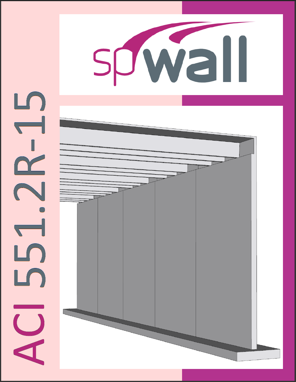
Reinforced Concrete Tilt-Up Wall Panel Analysis and Design (ACI 318-19 - ACI 551) (spWall v10.50)
Author: StructurePoint (SP)
Year: 2026
Pages: 40
Tilt-up is form of construction with increasing popularity owing to its flexibility and economics. Tilt-up concrete is essentially a precast concrete that is site cast instead of traditional factory cast concrete members. A structural reinforced concrete tilt-up wall panel in a single-story warehouse (big-box) building provides gravity and lateral load resistance for applied loads from three roof joists bearing in wall pockets in addition to the wind. The assumed tilt-up wall panel section and reinforcement are investigated after analysis to verify suitability for the applied loads based on the comprehensive procedure provided by ACI 551 and the provisions of the American code (ACI 318-19). Then the results are compared with numerical analysis results obtained from spWall v10.50 engineering software program by StructurePoint.
Reinforced Concrete Tilt-Up Wall Panel Analysis and Design (ACI 318-14 - ACI 551) (spWall v10.00)
Author: StructurePoint (SP)
Year: 2023
Pages: 37
Tilt-up is form of construction with increasing popularity owing to its flexibility and economics. Tilt-up concrete is essentially a precast concrete that is site cast instead of traditional factory cast concrete members. A structural reinforced concrete tilt-up wall panel in a single-story warehouse (big-box) building provides gravity and lateral load resistance for applied loads from three roof joists bearing in wall pockets in addition to the wind. The assumed tilt-up wall panel section and reinforcement are investigated after analysis to verify suitability for the applied loads based on the comprehensive procedure provided by ACI 551 and the provisions of the American code (ACI 318-14). Then the results are compared with numerical analysis results obtained from spWall v10 engineering software program from StructurePoint.
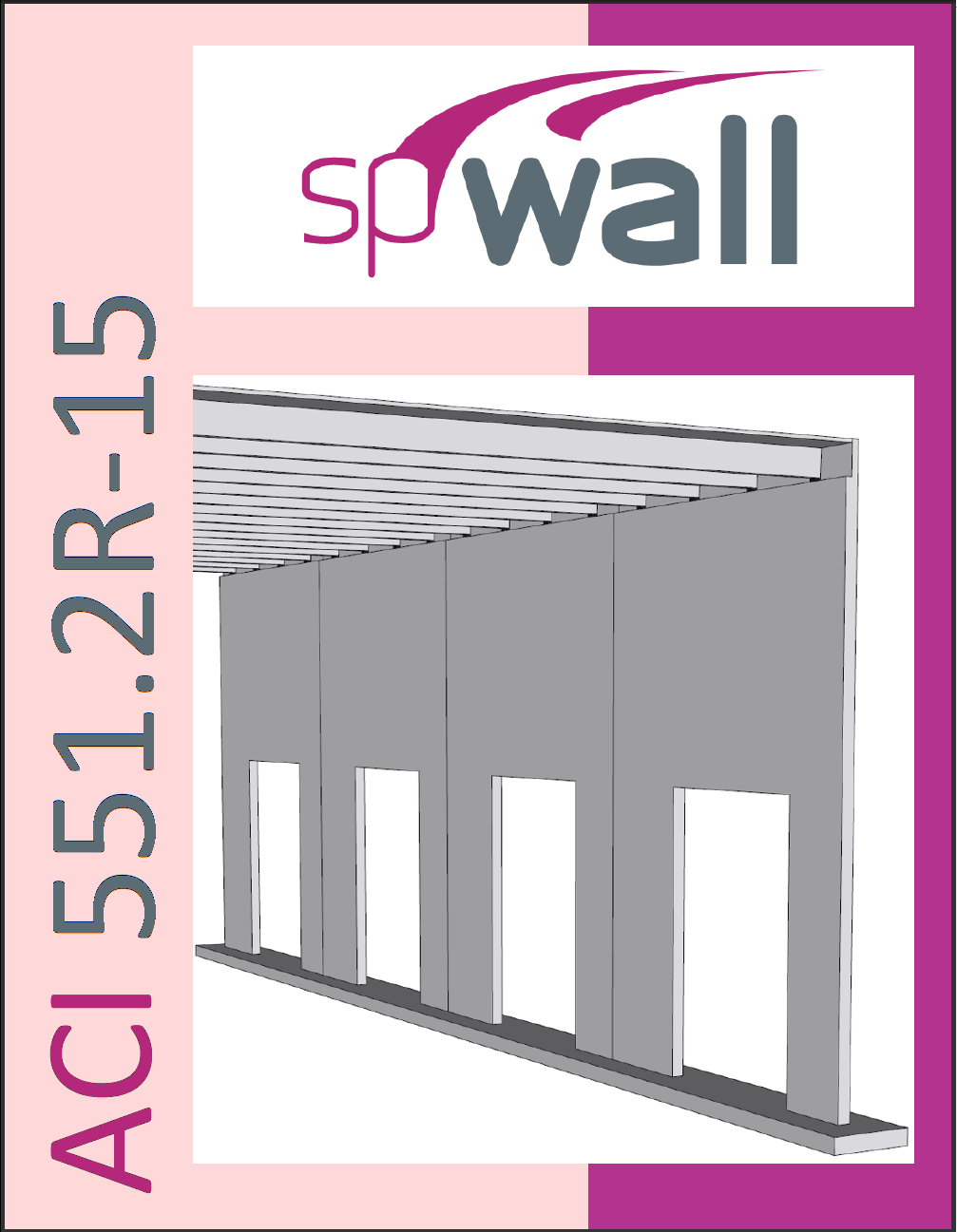
Reinforced Concrete Tilt-Up Wall Panel with Opening Analysis and Design (ACI 318-19) (spWall v10.50)
Author: StructurePoint (SP)
Year: 2026
Pages: 54
Tilt-up is form of construction with increasing popularity owing to its flexibility and economics. Tilt-up concrete is essentially a precast concrete that is site cast instead of traditional factory cast concrete members. A structural reinforced concrete tilt-up wall panel with opening in a single-story warehouse (big-box) building provides gravity and lateral load resistance for applied loads from three roof joists bearing in wall pockets in addition to wind load. The assumed tilt-up wall panel section and reinforcement are investigated after analysis to verify suitability for the applied loads based on the provisions of the American code (ACI 318-19). Then the results are compared with numerical analysis results obtained from spWall v10.50 engineering software program from StructurePoint. The following advanced topics are also discussed: tilt-up wall stiffness reduction, loading type effects, and cracking coefficient optimization.
Reinforced Concrete Tilt-Up Wall Panel with Opening Analysis and Design (ACI 318-14 - ACI 551) (spWall v10.00)
Author: StructurePoint (SP)
Year: 2023
Pages: 51
Tilt-up is form of construction with increasing popularity owing to its flexibility and economics. Tilt-up concrete is essentially a precast concrete that is site cast instead of traditional factory cast concrete members. A structural reinforced concrete tilt-up wall panel with opening in a single-story warehouse (big-box) building provides gravity and lateral load resistance for applied loads from three roof joists bearing in wall pockets in addition to wind load. The assumed tilt-up wall panel section and reinforcement are investigated after analysis to verify suitability for the applied loads based on the comprehensive procedure provided by ACI 551 and the provisions of the American code (ACI 318-14). Then the results are compared with numerical analysis results obtained from spWall v10 engineering software program from StructurePoint. The following advanced topics are also discussed: tilt-up wall stiffness reduction, loading type effects, and cracking coefficient optimization.
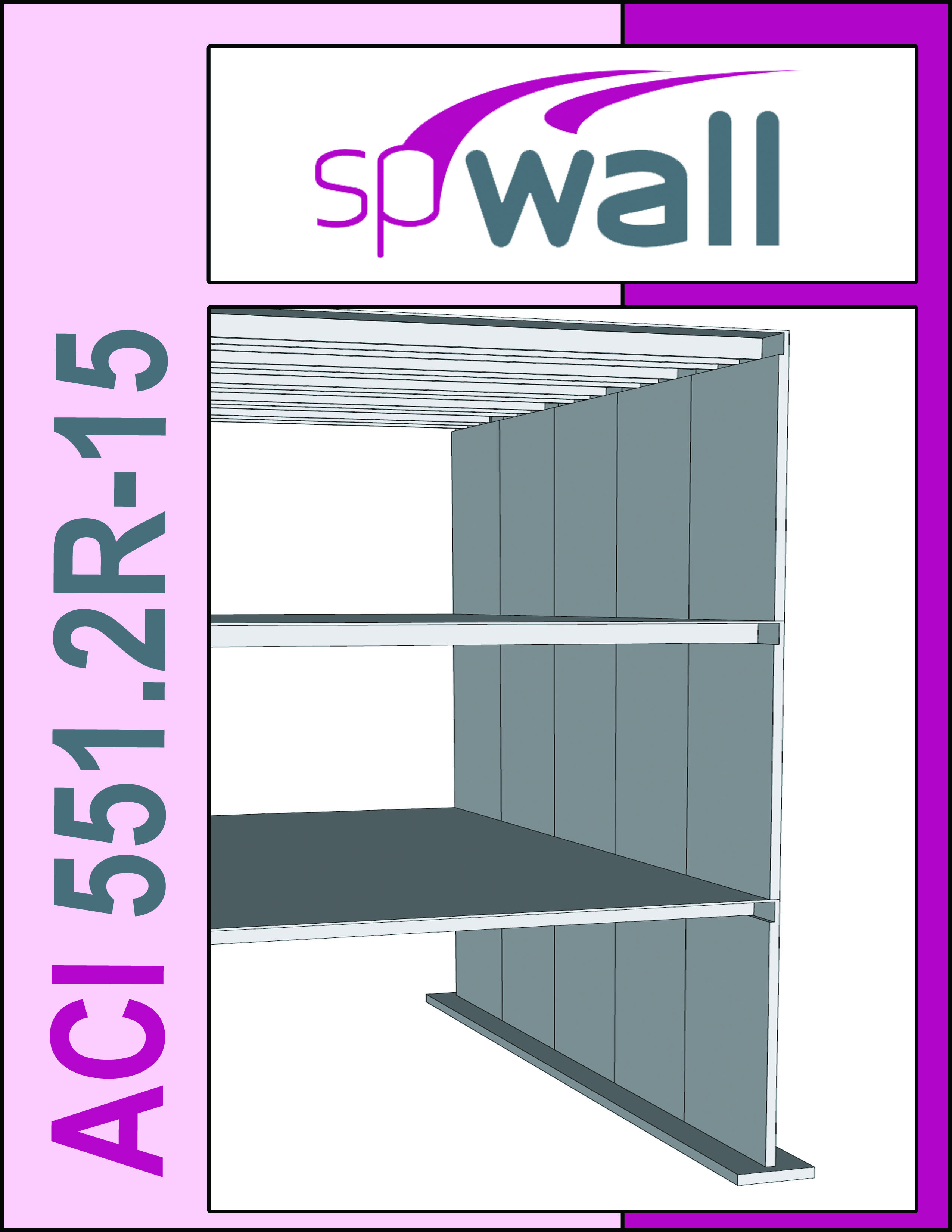
Multi-Story Solid Tilt-Up Wall Panel Analysis and Design (ACI 318-19) (spWall v10.50)
Author: StructurePoint (SP)
Year: 2026
Pages: 39
A structural reinforced concrete tilt-up wall panel provides gravity and lateral load resistance in a multi-story building is investigated based on the provisions of the American code (ACI 318-19). Then the results are compared with numerical analysis results obtained from spWall v10.50 engineering software program from StructurePoint.
Multi-Story Solid Tilt-Up Wall Panel Analysis and Design (ACI 318-14 - ACI 551) (spWall v10.00)
Author: StructurePoint (SP)
Year: 2023
Pages: 35
A structural reinforced concrete tilt-up wall panel provides gravity and lateral load resistance in a multi-story building is investigated based on the comprehensive procedure provided by ACI 551 and the provisions of the American code (ACI 318-14). Then the results are compared with numerical analysis results obtained from spWall v10.00 engineering software program from StructurePoint.
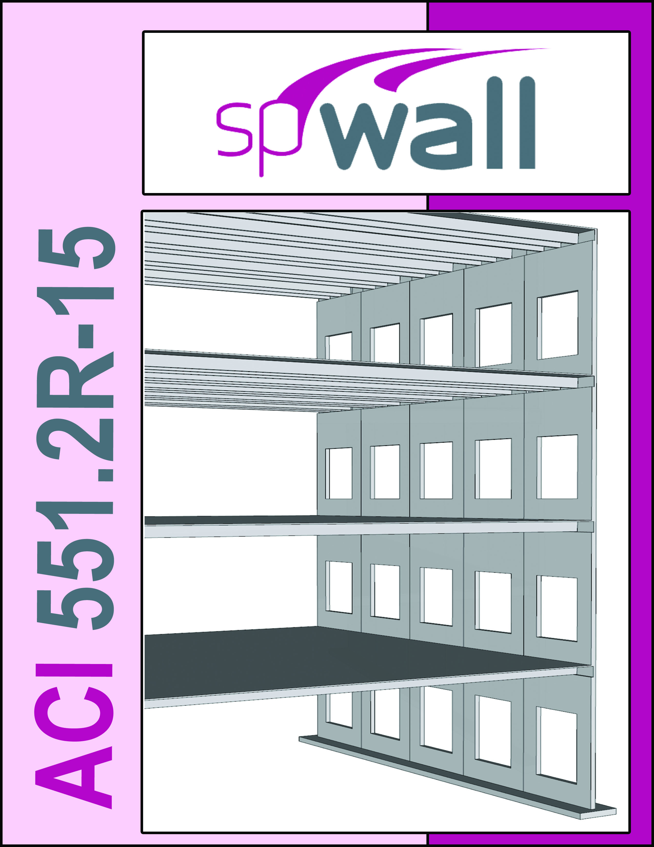
Multi-Story Tilt-Up Wall Panel with Openings Analysis and Design (ACI 318-19) (spWall v10.50)
Author: StructurePoint (SP)
Year: 2026
Pages: 44
A structural reinforced concrete tilt-up wall panel with openings provides gravity and lateral load resistance in a multi-story building is investigated based on the provisions of the American code (ACI 318-19). Then the results are compared with numerical analysis results obtained from spWall v10.50 engineering software program from StructurePoint. Additionally, different modeling and analysis techniques using spWall engineering software program to investigate and design tilt-up wall panels with openings are discussed.
Multi-Story Tilt-Up Wall Panel with Openings Analysis and Design (ACI 318-14 - ACI 551) (spWall v10.00)
Author: StructurePoint (SP)
Year: 2023
Pages: 41
A structural reinforced concrete tilt-up wall panel with openings provides gravity and lateral load resistance in a multi-story building is investigated based on the comprehensive procedure provided by ACI 551 and the provisions of the American code (ACI 318-14). Then the results are compared with numerical analysis results obtained from spWall v10 engineering software program from StructurePoint. Additionally, different modeling and analysis techniques using spWall engineering software program to investigate and design tilt-up wall panels with openings are discussed.

Reinforced Concrete Cantilever Retaining Wall Analysis and Design (ACI 318-19) (spWall v10.50)
Author: StructurePoint (SP)
Year: 2026
Pages: 45
Reinforced concrete cantilever retaining walls consist of a relatively thin stem and a base slab. The stem may have constant thickness along the length or may be tapered based on economic and construction criteria. The base is divided into two parts, the heel and toe. Cantilever retaining walls are considered economical up to about 25 ft in height. This design example focuses on the analysis and design of a tapered cantilever retaining wall based on the provisions of the American code (ACI 318-19). The hand solution is used for a detailed comparison with the finite element analysis and design results of spWall v10.50 and spMats v10.50 engineering software programs from StructurePoint. The retaining wall is fixed to the reinforced concrete slab foundation with a shear key for sliding resistance.

Reinforced Concrete Cantilever Retaining Wall Analysis and Design (ACI 318-14) (spWall v10.00)
Author: StructurePoint (SP)
Year: 2023
Pages: 42
Reinforced concrete cantilever retaining walls consist of a relatively thin stem and a base slab. The stem may have constant thickness along the length or may be tapered based on economic and construction criteria. The base is divided into two parts, the heel and toe. Cantilever retaining walls are considered economical up to about 25 ft in height. This design example focuses on the analysis and design of a tapered cantilever retaining wall based on the provisions of the American code (ACI 318-14). The hand solution is used for a detailed comparison with the finite element analysis and design results of spWall v10 and spMats v10 engineering software programs from StructurePoint. The retaining wall is fixed to the reinforced concrete slab foundation with a shear key for sliding resistance.
Design of Deep Beam (Transfer Girder) Using Strut-and-Tie Model (ACI 318-14) (spWall v10.00)
Author: StructurePoint (SP)
Year: 2023
Pages: 36
In this example, a reinforced concrete transfer girder (deep beam) is analyzed and designed using the Strut-and-Tie Method (STM) using the provisions of the American code (ACI 318-14). The hand solution is used for a detailed comparison with the finite element analysis and design results of spWall v10 engineering software program from StructurePoint.
Reinforced Concrete Shear Wall Analysis and Design (ACI 318-14) (spWall v5.01)
Format: (PDF)
Author: StructurePoint (SP)
Year: 2018
Pages: 27
The analysis and design of reinforced concrete shear wall as shown in this example is essential to lateral load resistance for wind and seismic forces. The hand solution is used for a detailed comparison with the analysis and design results of the engineering software program spWall.
Precast Concrete Bearing Wall Panel Design (Alternative Design Method) (Using ACI 318-11) (spWall v5.01)
Format: (PDF)
Author: StructurePoint (SP)
Year: 2017
Pages: 23
This example illustrates the analysis and design of precast reinforced concrete bearing wall panel in a single-story building. The panel provides load resistance for gravity loads from double tee roof framing and applied lateral wind loads. Alternative Design Method for Out-of-Plane Slender Wall in ACI 318 is used to demonstrate hand calculation procedures and compare with finite element analysis results from engineering software program spWall. The impact of cracking on stiffness reduction represented by the magnitude of cracked and effective moment of inertia is highlighted in the analysis results including forces and deflections.
Precast Concrete Bearing Wall Panel Design (Alternative Analysis Method) (Using ACI 318-14) (spWall v5.01)
Format: (PDF)
Author: StructurePoint (SP)
Year: 2017
Pages: 23
This example illustrates the analysis and design of precast reinforced concrete bearing wall panel in a single-story building. The panel provides load resistance for gravity loads from double tee roof framing and applied lateral wind loads. Alternative Method for Out-of-Plane Slender Wall Analysis in ACI 318 is used to demonstrate hand calculation procedures and compare with finite element analysis results from engineering software program spWall. The impact of cracking on stiffness reduction represented by the magnitude of cracked and effective moment of inertia is highlighted in the analysis results including forces and deflections.
Reinforced Concrete Tilt-Up Wall Panel Analysis and Design (ACI 551) (spWall v5.01)
Format: (PDF)
Author: StructurePoint (SP)
Year: 2017
Pages: 18
Tilt-up is form of construction with increasing popularity owing to its flexibility and economics. Tilt-up concrete is essentially a precast concrete that is site cast instead of traditional factory cast concrete members. A structural reinforced concrete tilt-up wall panel in a single-story warehouse (big-box) building provides gravity and lateral load resistance for applied loads from three roof joists bearing in wall pockets in addition to the wind. The assumed tilt-up wall panel section and reinforcement are investigated after analysis to verify suitability for the applied loads then compared with numerical analysis results obtained from spWall engineering software program from StructurePoint.
Reinforced Concrete Tilt-Up Wall Panel with Opening Analysis and Design (ACI 551) (spWall v5.01)
Format: (PDF)
Author: StructurePoint (SP)
Year: 2017
Pages: 30
Tilt-up is form of construction with increasing popularity owing to its flexibility and economics. Tilt-up concrete is essentially a precast concrete that is site cast instead of traditional factory cast concrete members. A structural reinforced concrete tilt-up wall panel with opening in a single-story warehouse (big-box) building provides gravity and lateral load resistance for applied loads from three roof joists bearing in wall pockets in addition to wind load. The assumed tilt-up wall panel section and reinforcement are investigated after analysis to verify suitability for the applied loads then compared with numerical analysis results obtained from spWall engineering software program from StructurePoint. Additionally, different modeling and analysis techniques using spWall engineering software program to investigate and design tilt-up wall panels with openings are discussed.
Multi-Story Solid Tilt-Up Wall Panel Analysis and Design (ACI 551) (spWall v5.01)
Format: (PDF)
Author: StructurePoint (SP)
Year: 2018
Pages: 26
A structural reinforced concrete tilt-up wall panel provides gravity and lateral load resistance in a multi-story building is investigated using the procedure in ACI 551 and compared with the results of spWall engineering software program from StructurePoint.
Multi-Story Tilt-Up Wall Panel with Openings Analysis and Design (ACI 551) (spWall v5.01)
Format: (PDF)
Author: StructurePoint (SP)
Year: 2018
Pages: 30
A structural reinforced concrete tilt-up wall panel with openings provides gravity and lateral load resistance in a multi-story building is investigated using the procedure in ACI 551 and compared with the results of spWall engineering software program from StructurePoint. Additionally, different modeling and analysis techniques using spWall engineering software program to investigate and design tilt-up wall panels with openings are discussed.

Reinforced Concrete Cantilever Retaining Wall Analysis and Design (ACI 318-14) (spWall v5.01)
Format: (PDF)
Author: StructurePoint (SP)
Year: 2019
Pages: 30
Reinforced concrete cantilever retaining walls consist of a relatively thin stem and a base slab. The stem may have constant thickness along the length or may be tapered based on economic and construction criteria. The base is divided into two parts, the heel and toe. Cantilever retaining walls are considered economical up to about 25 ft in height. This design example focuses on the analysis and design of a tapered cantilever retaining wall including a comparison with model results from the engineering software programs spWall and spMats. The retaining wall is fixed to the reinforced concrete slab foundation with a shear key for sliding resistance.
Design of Deep Beam (Transfer Girder) Using Strut-and-Tie Model (ACI 318-11) (spWall v5.01)
Format: (PDF)
Author: StructurePoint (SP)
Year: 2021
Pages: 28
In this example, a reinforced concrete transfer girder (deep beam) is analyzed and designed using the Strut-and-Tie Method (STM). The results obtained from STM following ACI 318 procedure, are then compared with numerical finite element analysis results obtained from spWall engineering software program from StructurePoint.
Reinforced Concrete Shear Wall Analysis and Design (CSA A23.3-19) (spWall v10.50)
Author: StructurePoint (SP)
Year: 2026
Pages: 39
The analysis and design of reinforced concrete shear wall is essential to lateral load resistance for wind and seismic forces. In this example, shear wall section and assumed reinforcement is investigated after analysis to verify suitability for the applied loads based on CSA A23.3-19 provisions, then compared with numerical analysis results obtained from spWall v10.50 engineering software program by StructurePoint.
Reinforced Concrete Shear Wall Analysis and Design (CSA A23.3-14) (spWall v10.00)
Author: StructurePoint (SP)
Year: 2023
Pages: 38
The analysis and design of reinforced concrete shear wall is essential to lateral load resistance for wind and seismic forces. In this example, shear wall section and assumed reinforcement is investigated after analysis to verify suitability for the applied loads based on CSA A23.3-14 provisions, then compared with numerical analysis results obtained from spWall v10 engineering software program from StructurePoint.
Reinforced Concrete Bearing Wall Design (CSA A23.3-19) (spWall v10.50)
Author: StructurePoint (SP)
Year: 2026
Pages: 27
This example illustrates the analysis and design of reinforced concrete bearing wall in a single-story building based on the provisions of the Canadian code (CSA A23.3-19). The wall provides load resistance for gravity loads. Simplified Equation Method is used to demonstrate hand calculation procedure. The values from hand calculations are compared with the finite element analysis results obtained from spWall v10.50 engineering software program by StructurePoint.
Reinforced Concrete Bearing Wall Design (CSA A23.3-14) (spWall v10.00)
Author: StructurePoint (SP)
Year: 2023
Pages: 29
This example illustrates the analysis and design of reinforced concrete bearing wall in a single-story building based on the provisions of the Canadian code (CSA A23.3-14). The wall provides load resistance for gravity loads. Simplified Equation Method is used to demonstrate hand calculation procedure. The values obtained in the reference and the hand calculations are compared with the finite element analysis results obtained from spWall v10 engineering software program from StructurePoint.
Reinforced Concrete Shear Wall Analysis and Design (CSA A23.3-14) (spWall v5.01)
Format: (PDF)
Author: StructurePoint (SP)
Year: 2021
Pages: 21
The analysis and design of reinforced concrete shear wall is essential to lateral load resistance for wind and seismic forces. In this example, shear wall section and assumed reinforcement is investigated after analysis to verify suitability for the applied loads based on CSA A23.3-14 provisions, then compared with numerical analysis results obtained from spWall engineering software program from StructurePoint.
Reinforced Concrete Bearing Wall Design (CSA A23.3-14) (spWall v5.01)
Format: (PDF)
Author: StructurePoint (SP)
Year: 2021
Pages: 18
This example illustrates the analysis and design of reinforced concrete bearing wall in a single-story building. The wall provides load resistance for gravity loads. Simplified Equation Method is used to demonstrate hand calculation procedure. The values obtained in the reference and the hand calculations are compared with numerical analysis results obtained from spWall engineering software program from StructurePoint.
Reinforced Concrete Tilt-Up Wall Panel Analysis and Design (CSA A23.3-14) (spWall v5.01)
Format: (PDF)
Author: StructurePoint (SP)
Year: 2018
Pages: 17
Tilt-up is form of construction with increasing popularity owing to its flexibility and economics. Tilt-up concrete is essentially a precast concrete that is site cast instead of traditional factory cast concrete members. A structural reinforced concrete tilt-up wall panel in a single-story warehouse (big-box) building provides gravity and lateral load resistance for applied loads from three roof joists bearing in wall pockets in addition to the wind. The assumed tilt-up wall panel section and reinforcement are investigated after analysis (using CSA A23.3-14) to verify suitability for the applied loads then compared with numerical analysis results obtained from spWall engineering software program from StructurePoint.
Reinforced Concrete Cantilever Retaining Wall Foundation Analysis and Design (ACI 318-19) (spMats v10.50)
Author: StructurePoint (SP)
Year: 2026
Pages: 45
Reinforced concrete cantilever retaining walls consist of a relatively thin stem and a base slab. The stem may have constant thickness along the length or may be tapered based on economic and construction criteria. The base is divided into two parts, the heel and toe. Cantilever retaining walls are considered economical up to about 25 ft in height. This design example focuses on the analysis and design of a tapered cantilever retaining wall based on the provisions of the American code (ACI 318-19). The hand solution is used for a detailed comparison with the finite element analysis and design results of spWall v10.50 and spMats v10.50 engineering software programs from StructurePoint. The retaining wall is fixed to the reinforced concrete slab foundation with a shear key for sliding resistance.
Reinforced Concrete Cantilever Retaining Wall Foundation Analysis and Design (ACI 318-14) (spMats v10.00)
Author: StructurePoint (SP)
Year: 2023
Pages: 42
Reinforced concrete cantilever retaining walls consist of a relatively thin stem and a base slab. The stem may have constant thickness along the length or may be tapered based on economic and construction criteria. The base is divided into two parts, the heel and toe. Cantilever retaining walls are considered economical up to about 25 ft in height. This design example focuses on the analysis and design of a tapered cantilever retaining wall based on the provisions of the American code (ACI 318-14). The hand solution is used for a detailed comparison with the finite element analysis and design results of spWall v10 and spMats v10 engineering software programs from StructurePoint. The retaining wall is fixed to the reinforced concrete slab foundation with a shear key for sliding resistance.
Reinforced Concrete Square Footing Analysis and Design (ACI 318-14) (spMats v8.50)
Format: (PDF)
Author: StructurePoint (SP)
Year: 2018
Pages: 17
A spread footing supporting a square column is designed using provisions of ACI 318-14. The hand solution is used for a comparison with the finite element analysis and design results of the engineering software program spMats.
Reinforced Concrete Shear Wall Foundation (Strip Footing) Analysis and Design (ACI 318-14) (spMats v8.50)
Format: (PDF)
Author: StructurePoint (SP)
Year: 2017
Pages: 15
The analysis and design of reinforced concrete shear wall footing (strip footing) is shown in this example. The hand solution is used for a detailed comparison with the analysis and design results of the engineering software program spMats using the Finite Element Analysis (FEA) method.
Reinforced Concrete Column Combined Footing Analysis and Design (ACI 318-14) (spMats v8.50)
Format: (PDF)
Author: StructurePoint (SP)
Year: 2017
Pages: 19
The analysis and design of reinforced concrete combined footing is shown in this example. The hand solution is used for a detailed comparison with the analysis and design results of the engineering software program spMats using the Finite Element Analysis (FEA) method.
Pile Supported Foundation (Pile Cap) Analysis and Design (ACI 318-14) (spMats v8.50)
Format: (PDF)
Author: StructurePoint (SP)
Year: 2018
Pages: 34
The analysis procedure shown in ACI 318-14 is illustrated in detail to analyze and design pile cap systems. The hand solution is also used for a detailed comparison with the analysis and design results of the engineering software program spMats.
Reinforced Concrete Cantilever Retaining Wall Foundation Analysis and Design (ACI 318-14) (spMats v8.50)
Format: (PDF)
Author: StructurePoint (SP)
Year: 2019
Pages: 30
Reinforced concrete cantilever retaining walls consist of a relatively thin stem and a base slab. The stem may have constant thickness along the length or may be tapered based on economic and construction criteria. The base is divided into two parts, the heel and toe. Cantilever retaining walls are considered economical up to about 25 ft in height. This design example focuses on the analysis and design of a tapered cantilever retaining wall including a comparison with model results from the engineering software programs spWall and spMats. The retaining wall is fixed to the reinforced concrete slab foundation with a shear key for sliding resistance.
Structural Analysis of Reinforced Concrete Frames
Format: (PDF)
Author: StructurePoint (SP)
Year: 2018
Pages: 26
Moment, shear, and axial forces using the Portal Method are determined for three frames with different configurations. The results of hand calculations are then compared with numerical analysis results obtained from the spFrame engineering software program.