Analysis and Design of One-Way Slab/Beam Systems
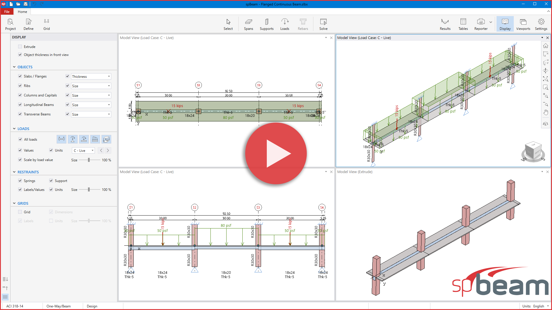
spBeam is structural engineering software for the analysis, design, and detailing of reinforced concrete one-way slab systems, continuous beams, and joist systems (including standard and wide module configurations).
With an intuitive graphical interface, engineers can define one-way slab and beam geometry, material properties, support conditions, and various loading scenarios, including point, line, and area loads. spBeam supports up to 20 spans and two cantilevers with live load patterning for efficient and accurate modeling of complex floor systems
Powered by a dynamic frame analysis and design engine, spBeam
adheres to the
American (ACI 318) and Canadian (CSA A23.3)
standards, automating calculations for flexural, shear,
and torsional
capacities, as well as immediate and long-term deflections. The
program enables moment
redistribution to reduce negative moments,
minimizing reinforcement congestion at supports and achieving
significant material and labor savings.
More
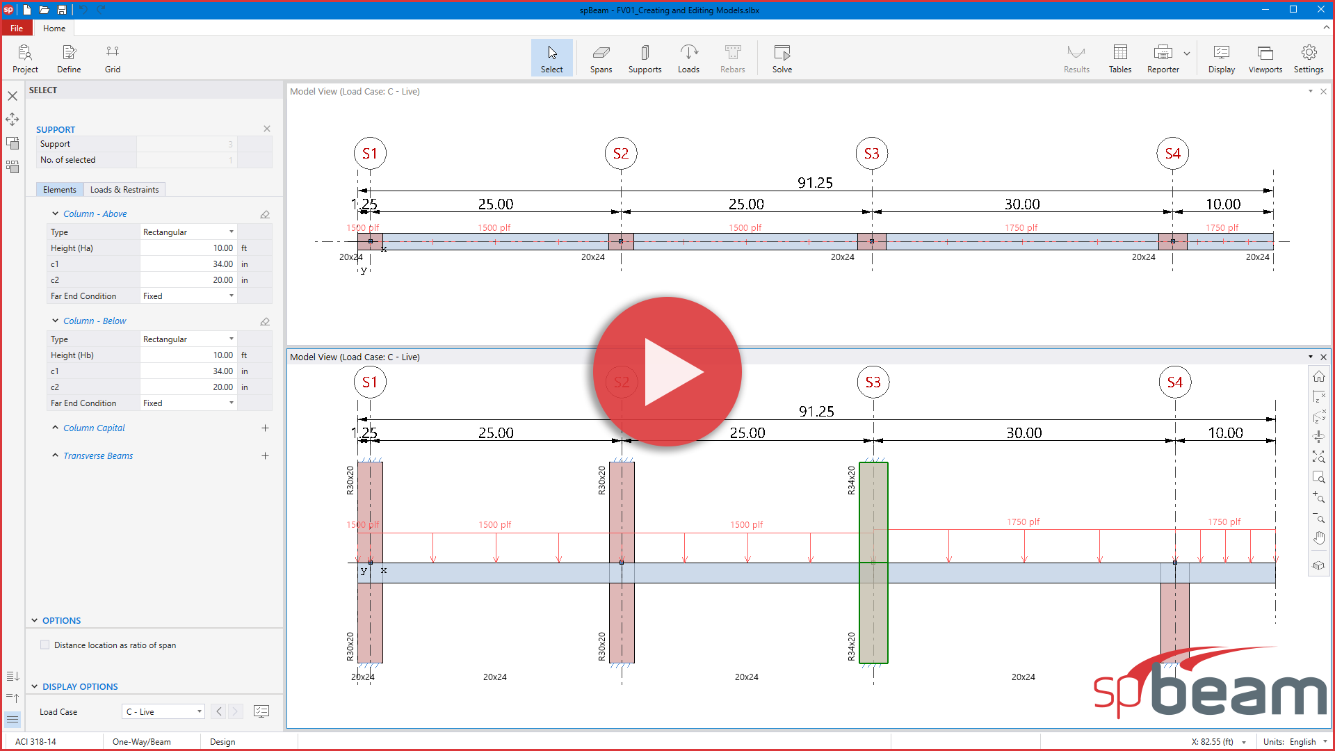
Create and Edit Concrete One-Way Slab or Beam Models in spBeam
Start with a template or create grids based on structural drawings to set up spans and support locations. Define and assign span elements (slabs, ribs and longitudinal beams), support elements (columns, capitals, and transverse beams) and loads to complete the model.
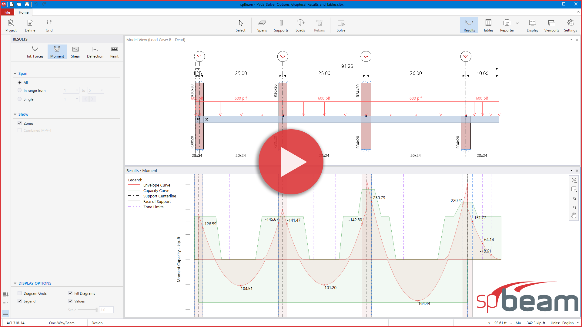
spBeam Solver Options, Graphical Results and Tables
Once the model is ready, the Solve command opens the Design and Deflection options, allowing users to customize the analysis settings. The spBeam dynamic frame analysis and design solver is then launched using the Run command. Results are provided in both tabular form and as diagrams.
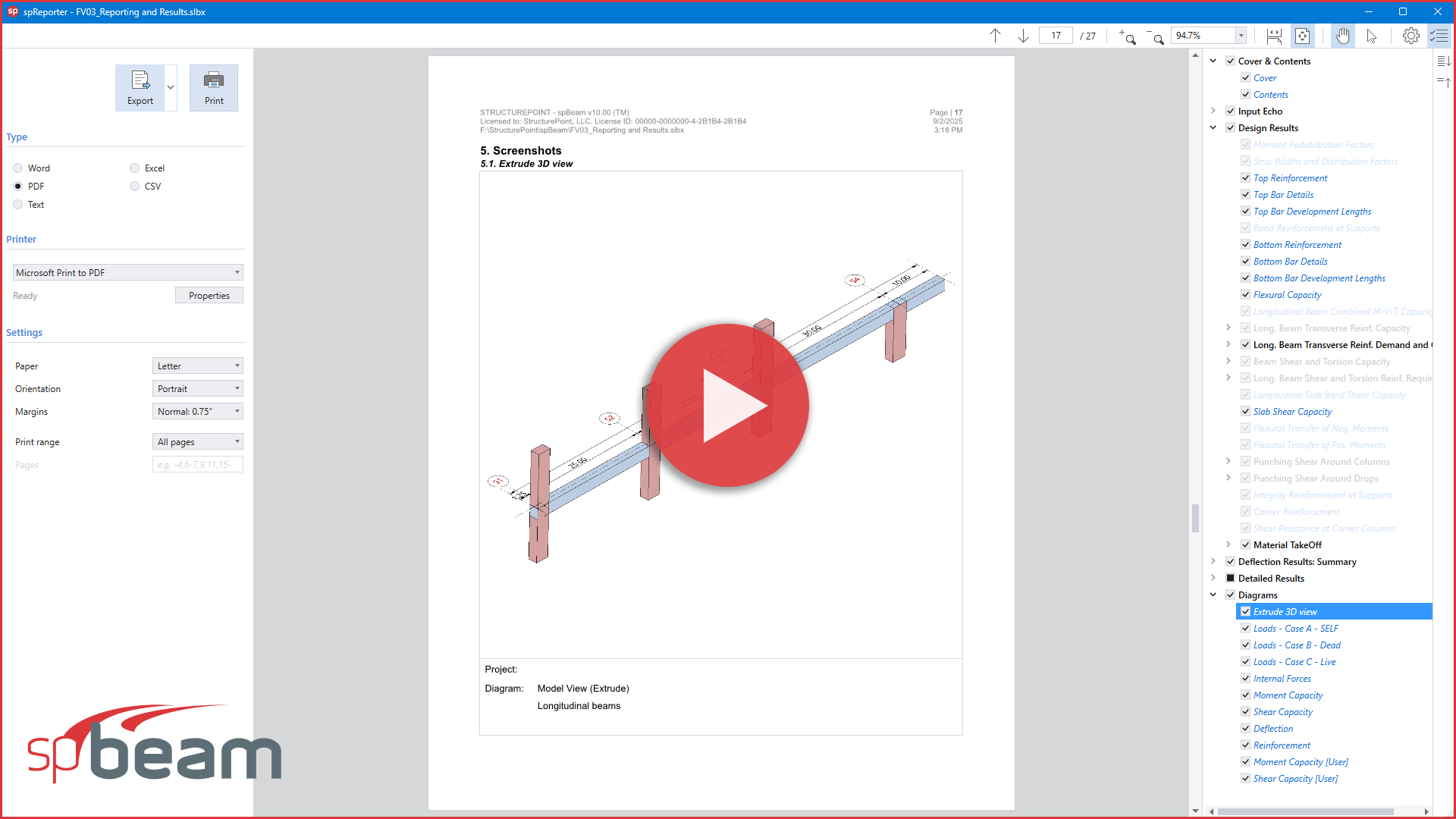
spBeam Reporting Results and Import/Export Options
spBeam features a modern reporting tool that allows users to view, customize, print, and export reports in various formats. The tool helps generate professional project submittals with flexible options to include as much or as little detail as needed. Users can also add detailed screenshots of diagrams to better illustrate structural behavior within the reports.
spBeam Templates Module
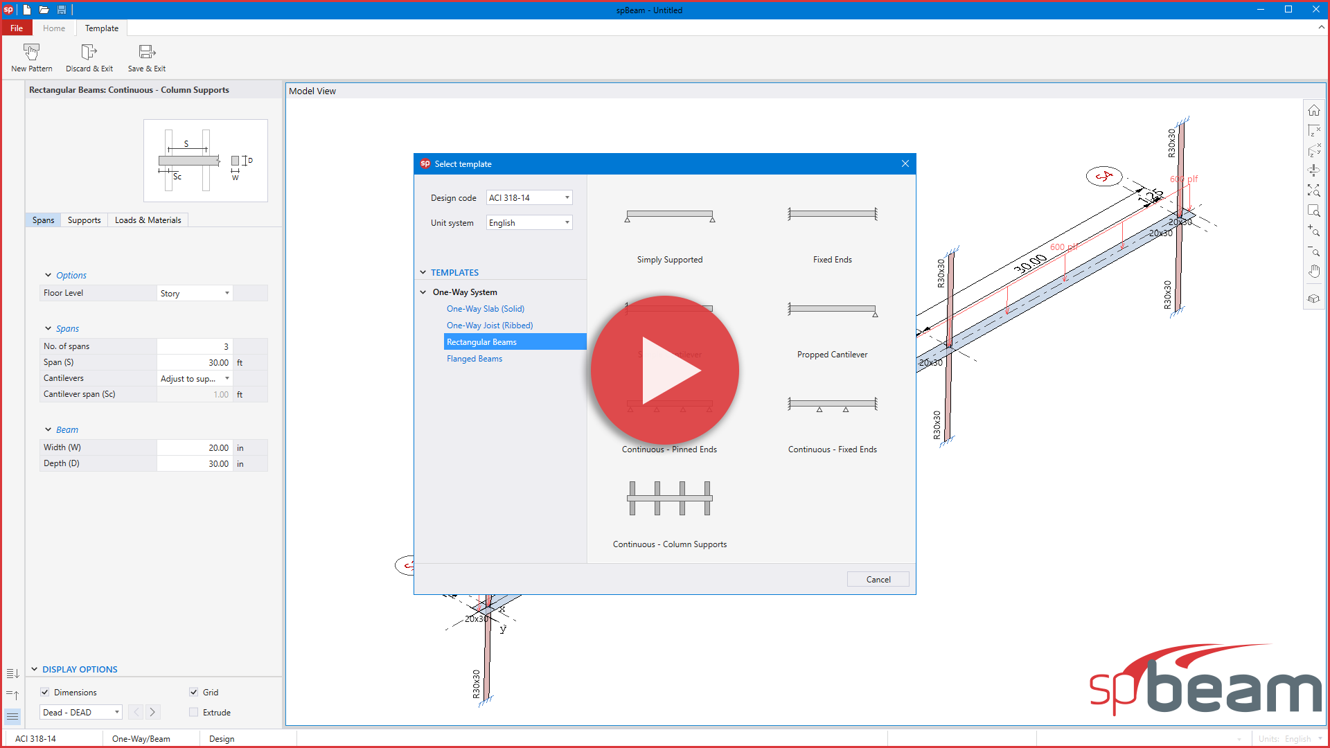
Templates in spBeam offer predefined one-way slab and beam systems, allowing users to create models simply, quickly, and accurately. Users can select from various one-way slab and beam categories and customize parameters like spans, supports, loads, and materials. Models are ready for analysis within minutes, with design results available for immediate review.
To the top
