


Beam on Elastic Foundation Analysis and Design
Format: (PDF)
Author: StructurePoint (SP)
Year: 2020
Pages: 41
Beams on elastic foundation (BEF) are very common in commercial, industrial and residential construction. Whether a grade beams in a prefabricated metal building, a combined footings for industrial tanks and equipment, or a footer beam for a tilt-up wall they feature soil-structure interaction. Beams on elastic foundations are structural members supported on continuous compressible elastic foundations such as soil or flowable fill. The reaction pressure due to external loading is distributed along the length of the beam and varies in intensity based on the elastic foundation stiffness. This study compares analysis results using the 1) Finite Element Method, 2) Stiffness Methods in spBeam and looks at the flexural and shear strength of beam on elastic foundation along with a review of required flexural reinforcement.
Flexural Strength of Flanged Reinforced Concrete Beam (T-Beam Section) - Case One
Format: (PDF)
Author: StructurePoint (SP)
Year: 2021
Pages: 15
This study determines the design flexural strength for flanged reinforced concrete beam (also known as T-beam) for the case where the depth of the equivalent rectangular stress block does not exceed the thickness of the flange. The beam is reinforced with two layers of bars on the tension side. The calculated values are compared with the values from the reference and the exact values obtained by spBeam engineering software program from StructurePoint.
Flexural Strength of Flanged Reinforced Concrete Beam (T-Beam Section) - Case Two
Format: (PDF)
Author: StructurePoint (SP)
Year: 2021
Pages: 15
This study determines the design flexural strength for isolated flanged reinforced concrete beam (also known as T-beam) for the case where the depth of the equivalent rectangular stress block exceeds the thickness of the flange. The beam is reinforced with two layers of bars on the tension side. The calculated values are compared with the values from the reference and the exact values obtained by spBeam engineering software program from StructurePoint.
Flexural Strength of Flanged Reinforced Concrete Beam (T-Beam Section) - Case Three
Format: (PDF)
Author: StructurePoint (SP)
Year: 2021
Pages: 16
This study determines the design flexural strength for isolated flanged reinforced concrete beam (also known as T-beam) for the case where the depth of the equivalent rectangular stress block exceeds the thickness of the flange. The beam is reinforced with three layers of bars on the tension side. The calculated values are compared with the values from the reference and the exact values obtained by spBeam engineering software program from StructurePoint.

Flexural Strength of Flanged Reinforced Concrete Beam (T-Beam Section) - Case Four
Format: (PDF)
Author: StructurePoint (SP)
Year: 2021
Pages: 17
This study determines the design flexural strength for an isolated flanged doubly reinforced concrete beam (also known as T-beam) for the case where the depth of the equivalent rectangular stress block does not exceed the thickness of the flange. The beam is reinforced with three layers of bars on the tension side, and one layer of bars on the compression side. The calculated values are compared with the values from the reference and the exact values obtained by spBeam engineering software program from StructurePoint.
Flexural Strength of Flanged Reinforced Concrete Beam (T-Beam Section) - Case Five
Format: (PDF)
Author: StructurePoint (SP)
Year: 2021
Pages: 17
This study determines the design flexural strength for an isolated flanged doubly reinforced concrete beam (also known as T-beam) for the case where the depth of the equivalent rectangular stress block exceeds the thickness of the flange. The beam is reinforced with three layers of bars on the tension side, and one layer of bars on the compression side. The calculated values are compared with the values from the reference and the exact values obtained by spBeam engineering software program from StructurePoint.
Flexural Design of Reinforced Concrete T-Beams (ACI 318-14)
Format: (PDF)
Author: StructurePoint (SP)
Year: 2021
Pages: 19
This example demonstrates the flexural design of a reinforced concrete T-beam using ACI 318-14 provisions. The hand and reference solutions are used for a detailed comparison with the results of the engineering software program spBeam.
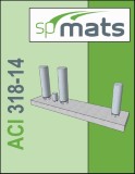
Pile (Caisson) Analysis and Design for Bridge Pier Foundations (ACI 318-19)
Author: StructurePoint (SP)
Year: 2025
Pages: 38
Reinforced concrete piles and caissons are essential deep foundation elements used to transfer structural loads to deeper, more stable soil or rock layers, especially in challenging conditions where shallow foundations are inadequate. Commonly used in foundations for bridge piers, buildings, and industrial facilities, these elements provide critical support against axial and lateral forces. In this case study, a pile supported mat foundation (known as pile cap) that supports a highway bridge pier will be modeled and analyzed using spMats to determine the individual pile reactions. these reactions will then be exported to spColumn to design and optimize the piles for two cases: (1) piles pinned to the pile cap and (2) piles fixed to the pile cap. Additionally, a comparison between different transverse confinement types (tied and spiral reinforcement) will be conducted to evaluate their influence on the pile capacity and behavior.

Insulating Concrete Forms (ICF) Walls Analysis and Design (ACI 318-14) (spWall v10)
Format: (PDF)
Author: StructurePoint (SP)
Year: 2023
Pages: 27
Insulating concrete form (ICF) is a concrete formwork system made of rigid thermal insulation that stays in place as a permanent interior and exterior substrate for walls, floors, and roofs. This case study focuses on the design of ICF walls based on the provisions of the American code (ACI 318-14) using spWall v10 engineering software program from StructurePoint. The ICF wall under study is in a typical four-story residential building with prestressed precast hollow core concrete plank floor with a 2 inch concrete cast in place topping. A review of the out of plane wind load displacement and support reactions along with the required reinforcement is included.

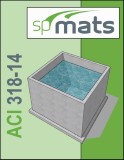
Rectangular Concrete Tank Walls Analysis and Design (ACI 318-19) (spWall v10.50)
Author: StructurePoint (SP)
Year: 2026
Pages: 39
Reinforced concrete tanks are used widely to collect and contain liquids from wastewater stations, process facilities, agricultural and environmental plants. This case study focuses on the design of a wastewater collection rectangular tank (pit) based on the provisions of the American code (ACI 318-19) and load combinations of (ACI 350R-06) using spWall v10.50 and spMats v10.50 engineering software programs from StructurePoint. The tank under study is a 13 ft high partially buried open top fixed at the base to a 12 in. reinforced concrete base mat.
Rectangular Concrete Tank Walls Analysis and Design (ACI 318-14 - ACI 350-06) (spWall v10)
Format: (PDF)
Author: StructurePoint (SP)
Year: 2023
Pages: 39
Reinforced concrete tanks are used widely to collect and contain liquids from wastewater stations, process facilities, agricultural and environmental plants. This case study focuses on the design of a wastewater collection rectangular tank (pit) based on the provisions of the American code (ACI 318-14) and load combinations of (ACI 350R-06) using spWall v10 and spMats v10 engineering software programs from StructurePoint. The tank under study is a 13 ft high partially buried open top fixed at the base to a 12 in. reinforced concrete base mat.
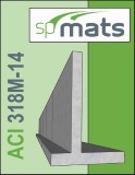
Reinforced Concrete Cantilever Retaining Wall Analysis and Design (ACI 318M-14) (spWall v10)
Format: (PDF)
Author: StructurePoint (SP)
Year: 2023
Pages: 33
Reinforced concrete cantilever retaining walls consist of a relatively thin stem and a base slab. The stem may have constant thickness along the length or may be tapered based on economic and construction criteria. The base is divided into two parts, the heel and toe. The heel is the part of the base under the backfill. This system uses much less concrete than monolithic gravity walls, but require more design and careful construction. Cantilever retaining walls can be precast in a factory or formed on site and considered economical up to about 7.5 m in height. This case study focuses on the analysis and design of a cantilever retaining wall based on the provisions of the American code (ACI 318M-14) with SI units using spWall v10 and spMats v10 engineering software programs from StructurePoint. The retaining wall is fixed to the reinforced concrete slab foundation and have a uniform cross section.

Reinforced Concrete Shear Wall Lateral Displacement and Stability in High-Rise Buildings (ACI 318-14/19) (spWall v10)
Format: (PDF)
Author: StructurePoint (SP)
Year: 2023
Pages: 13
The lateral displacement of shear wall in a high-rise building is investigated using different cracking coefficient equations based on the provisions of the American code (ACI 318-14) using spWall v10 engineering software program from StructurePoint.
Insulating Concrete Forms (ICF) Walls Analysis and Design (ACI 318-14) (spWall v5.01)
Format: (PDF)
Author: StructurePoint (SP)
Year: 2019
Pages: 16
Insulating concrete form (ICF) is a concrete formwork system made of rigid thermal insulation that stays in place as a permanent interior and exterior substrate for walls, floors, and roofs. This case study focuses on the design of ICF walls using the engineering software program spWall. The ICF wall under study is in a typical four-story residential building with prestressed precast hollow core concrete plank floor with a 2 inch concrete cast in place topping. A review of the out of plane wind load displacement and support reactions along with the required reinforcement is included.
Rectangular Concrete Tank Walls Analysis and Design (ACI 318-14 - ACI 350-06) (spWall v5.01)
Format: (PDF)
Author: StructurePoint (SP)
Year: 2019
Pages: 25
Reinforced concrete tanks are used widely to collect and contain liquids from wastewater stations, process facilities, agricultural and environmental plants. This case study focuses on the design of a wastewater collection rectangular tank (pit) using the engineering software programs spWall and spMats. The tank under study is a 13 ft high partially buried open top fixed at the base to a 12 in. reinforced concrete base mat.
Reinforced Concrete Cantilever Retaining Wall Analysis and Design (ACI 318M-14) (spWall v5.01)
Format: (PDF)
Author: StructurePoint (SP)
Year: 2019
Pages: 22
Reinforced concrete cantilever retaining walls consist of a relatively thin stem and a base slab. The stem may have constant thickness along the length or may be tapered based on economic and construction criteria. The base is divided into two parts, the heel and toe. The heel is the part of the base under the backfill. This system uses much less concrete than monolithic gravity walls, but require more design and careful construction. Cantilever retaining walls can be precast in a factory or formed on site and considered economical up to about 7.5 m in height. This case study focuses on the analysis and design of a cantilever retaining wall using the engineering software programs spWall and spMats. The retaining wall is fixed to the reinforced concrete slab foundation and have a uniform cross section. After examining the wall stability, it was concluded that shear key is not needed to resist wall sliding.
Reinforced Concrete Shear Wall Lateral Displacement and Stability in High-Rise Buildings (ACI 318-14/19) (spWall v5.01)
Format: (PDF)
Author: StructurePoint (SP)
Year: 2020
Pages: 11
The lateral displacement of shear wall in a high-rise building is investigated using different cracking coefficient equations using spWall engineering software program from StructurePoint.
Pile (Caisson) Analysis and Design for Bridge Pier Foundations (ACI 318-19)
Author: StructurePoint (SP)
Year: 2025
Pages: 38
Reinforced concrete piles and caissons are essential deep foundation elements used to transfer structural loads to deeper, more stable soil or rock layers, especially in challenging conditions where shallow foundations are inadequate. Commonly used in foundations for bridge piers, buildings, and industrial facilities, these elements provide critical support against axial and lateral forces. In this case study, a pile supported mat foundation (known as pile cap) that supports a highway bridge pier will be modeled and analyzed using spMats to determine the individual pile reactions. these reactions will then be exported to spColumn to design and optimize the piles for two cases: (1) piles pinned to the pile cap and (2) piles fixed to the pile cap. Additionally, a comparison between different transverse confinement types (tied and spiral reinforcement) will be conducted to evaluate their influence on the pile capacity and behavior.
Rectangular Concrete Tank Base Mat Analysis and Design (ACI 318-19) (spMats v10.50)
Author: StructurePoint (SP)
Year: 2026
Pages: 39
Reinforced concrete tanks are used widely to collect and contain liquids from wastewater stations, process facilities, agricultural and environmental plants. This case study focuses on the design of a wastewater collection rectangular tank (pit) based on the provisions of the American code (ACI 318-19) and load combinations of (ACI 350R-06) using spWall v10.50 and spMats v10.50 engineering software programs from StructurePoint. The tank under study is a 13 ft high partially buried open top fixed at the base to a 12 in. reinforced concrete base mat.
Rectangular Concrete Tank Base Mat Analysis and Design (ACI 350-06) (spMats v10.00)
Format: (PDF)
Author: StructurePoint (SP)
Year: 2023
Pages: 39
Reinforced concrete tanks are used widely to collect and contain liquids from wastewater stations, process facilities, agricultural and environmental plants. This case study focuses on the design of a wastewater collection rectangular tank (pit) based on the provisions of the American code (ACI 318-14) and load combinations of (ACI 350R-06) using spWall v10 and spMats v10 engineering software programs from StructurePoint. The tank under study is a 13 ft high partially buried open top fixed at the base to a 12 in. reinforced concrete base mat.

Tall Wind Turbine Tower Pile Cap Concrete Foundation Design
Format: (PDF)
Author: StructurePoint (SP)
Year: 2019
Pages: 24
A wind turbine is a device that converts the wind's kinetic energy into electrical energy. This case study focuses on the design of a 2.0 MW tall wind turbine tower foundation using the engineering software program spMats. Because of the tower height and the significant overturning moment generated, a circular pile cap foundation was recommended with an optimized arrangement of piles to best resist uplift forces. The concrete tower base and the piles are investigated in spColumn.
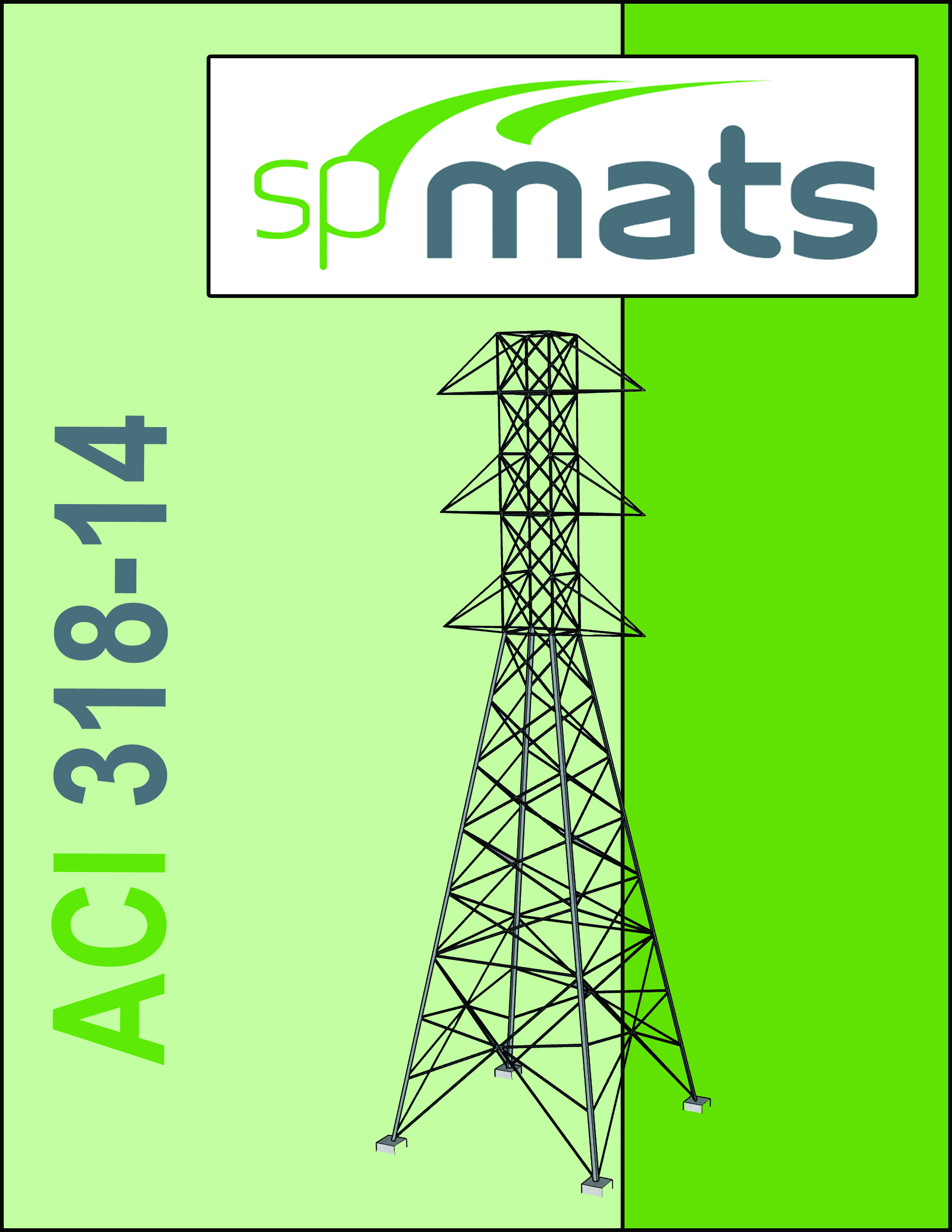
Transmission Tower Reinforced Concrete Pile Cap Foundation Design
Format: (PDF)
Author: StructurePoint (SP)
Year: 2019
Pages: 19
Transmission line towers support conductors carrying electrical power and one or two ground wires at suitable distances above the ground level and from each other. This case study focuses on the design of transmission tower foundation using the engineering software program spMats. The tower under study is a galvanized steel tower type 2DT6 for 230kV transmission line with a total height of 100 ft. A review of the pile reactions and displacements is included along with an investigation of the concrete pier and pile design capacity in spColumn.
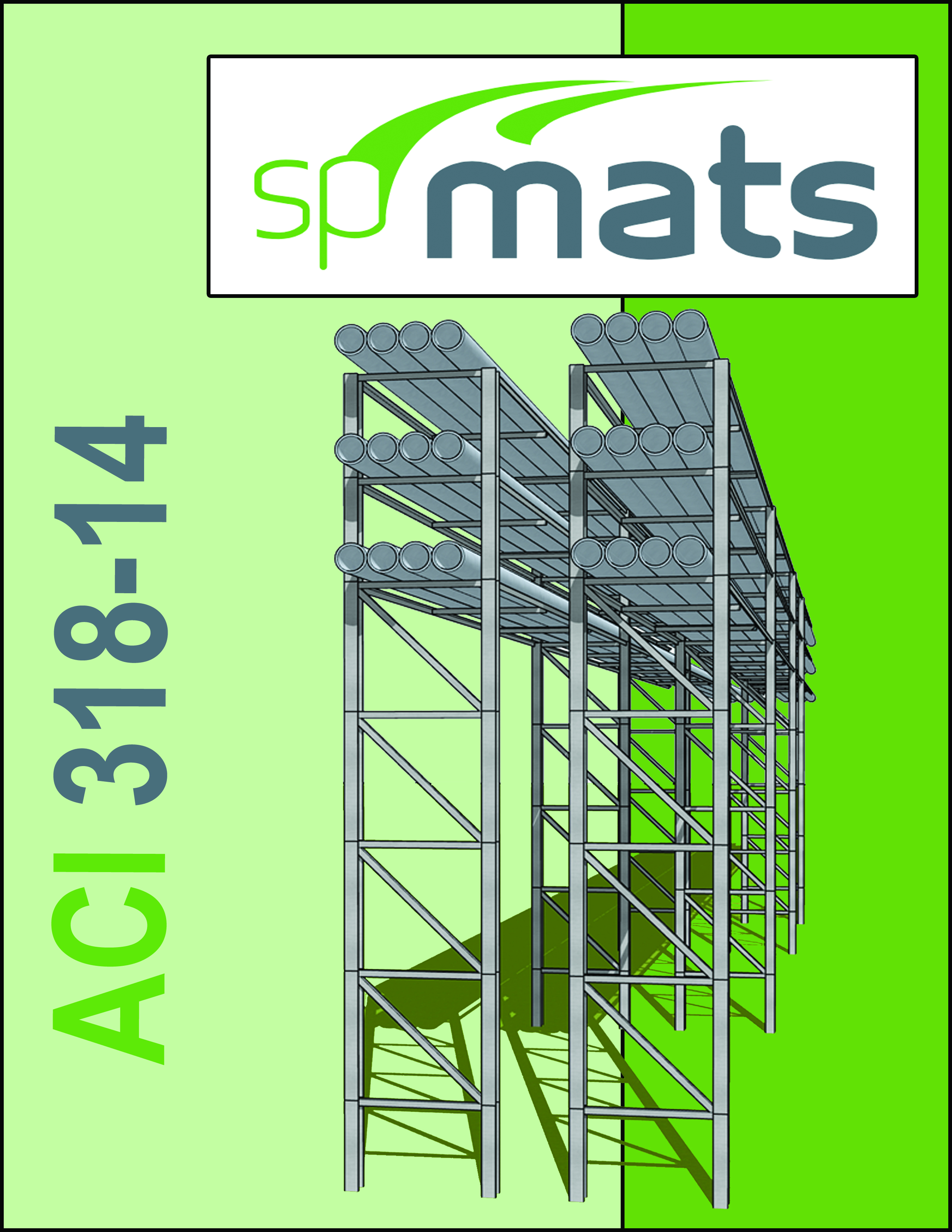
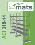
Industrial Plant Pipe Rack Pile Cap Foundation Analysis and Design
Format: (PDF)
Author: StructurePoint (SP)
Year: 2019
Pages: 26
Industrial pipe racks typically support pipes, power cables and instrument cable trays in petrochemical, chemical, paper mills and power plants. Occasionally, pipe racks may also support mechanical equipment, vessels and valve access platforms. This case study focuses on the design of pipe rack foundations using the engineering software program spMats. Three different pile supported foundation (pile cap) configurations are investigated including the design capacity of the concrete piers and piles.
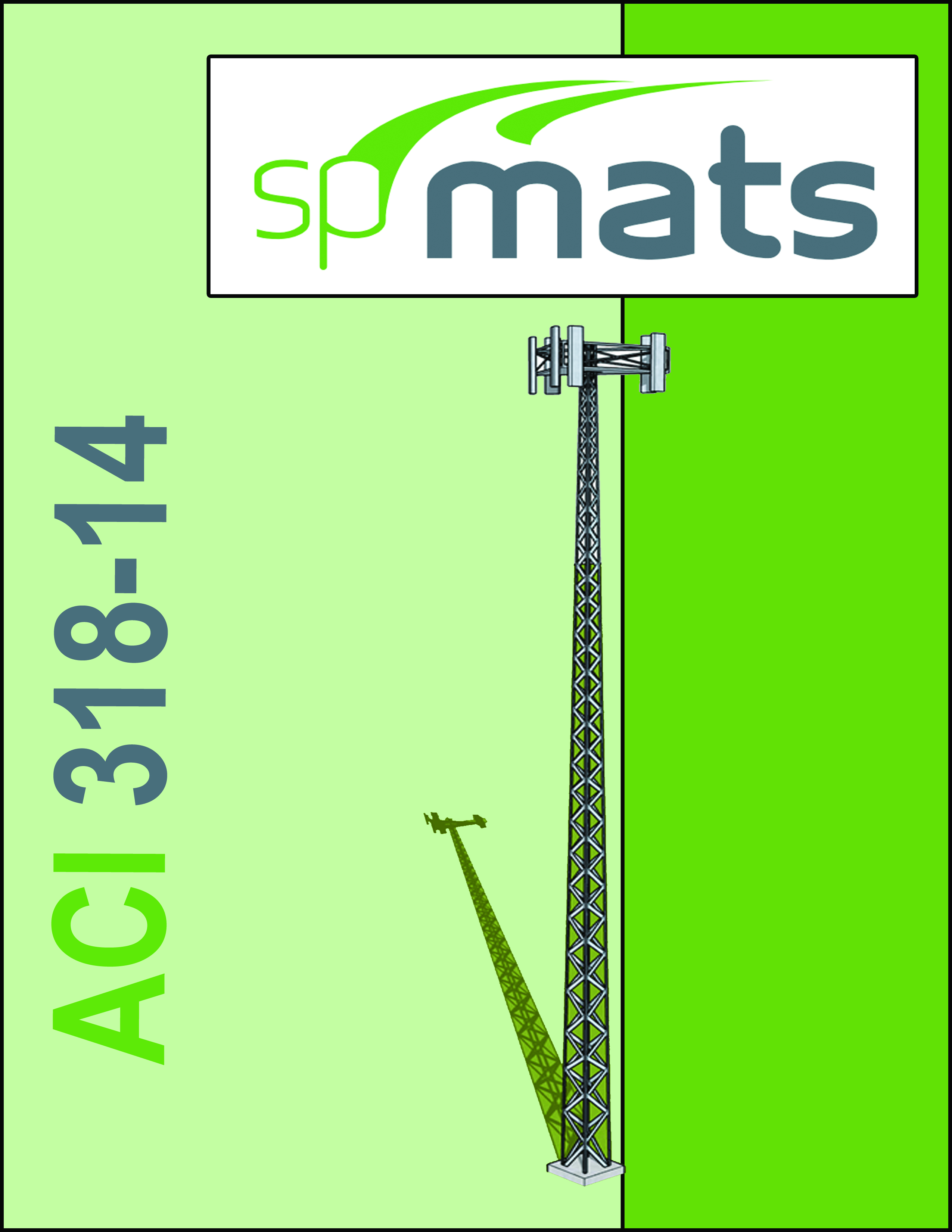
Wireless Telecommunication Tower Concrete Foundation Design
Format: (PDF)
Author: StructurePoint (SP)
Year: 2019
Pages: 21
Telecom (Telecommunications) towers are a generic description of radio masts and towers built primarily to hold telecommunications antennas and other applications such as microwave repeaters, wireless broadband, and dispatch equipment. This case study focuses on the design of a telecom tower foundation using the engineering software program spMats. The tower under study is a 100 ft high with a single legged soil supported concrete foundation. The tower concrete pier design capacity is investigated in spColumn.
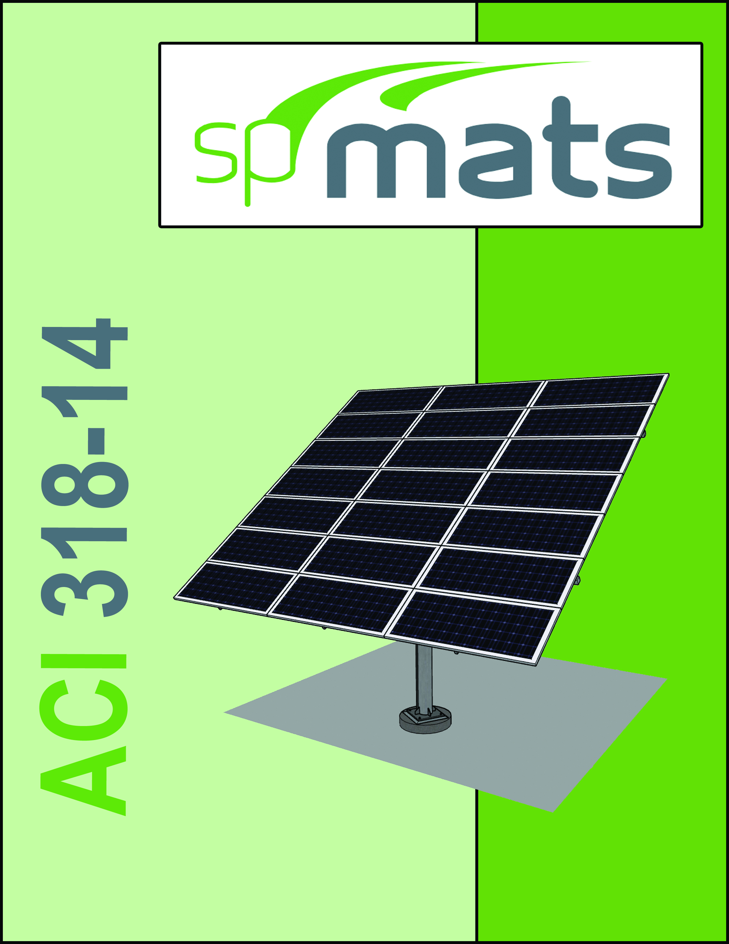
Ground Mounted PV Solar Panel Concrete Foundation Design
Format: (PDF)
Author: StructurePoint (SP)
Year: 2019
Pages: 22
A ground mounted solar panel system is a system of solar panels that are mounted on the ground rather than on the roof of buildings. The selected solar panel is known as Top-of-Pole Mount (TPM), where it is deigned to install quickly and provide a secure mounting structure for PV modules on a single pole. This case study focuses on the design of a ground mounted PV solar panel foundation using the engineering software program spMats. Because of available soil conditions at the site, a spread footing foundation is selected to resist applied gravity and wind loads. The supporting pole is welded to a base plate anchored to a 36 in. circular concrete pier.

Wind Turbine Tower Reinforced Concrete Foundation Analysis and Design
Format: (PDF)
Author: StructurePoint (SP)
Year: 2019
Pages: 23
A wind turbine is a device that converts the wind's kinetic energy into electrical energy. This case study focuses on the design of a typical wind turbine tower foundation using the engineering software program spMats. Given the soil conditions at the site and the equipment availability from the contractor, a soil supported foundation was selected to resist the significant overturning moments generated at the tower base. A review of the foundation settlement and reaction soil pressure is included in detail.
Rectangular Concrete Tank Base Mat Analysis and Design (ACI 350-06) (spMats v8.50)
Format: (PDF)
Author: StructurePoint (SP)
Year: 2019
Pages: 25
Reinforced concrete tanks are used widely to collect and contain liquids from wastewater stations, process facilities, agricultural and environmental plants. This case study focuses on the design of a wastewater collection rectangular tank (pit) using the engineering software programs spWall and spMats. The tank under study is a 13 ft high partially buried open top fixed at the base to a 12 in. reinforced concrete base mat.
Reinforced Concrete Cantilever Retaining Wall Foundation Analysis and Design (ACI 318M-14)
Format: (PDF)
Author: StructurePoint (SP)
Year: 2019
Pages: 22
Reinforced concrete cantilever retaining walls consist of a relatively thin stem and a base slab. The stem may have constant thickness along the length or may be tapered based on economic and construction criteria. The base is divided into two parts, the heel and toe. The heel is the part of the base under the backfill. This system uses much less concrete than monolithic gravity walls, but require more design and careful construction. Cantilever retaining walls can be precast in a factory or formed on site and considered economical up to about 7.5 m in height. This case study focuses on the analysis and design of a cantilever retaining wall using the engineering software programs spWall and spMats. The retaining wall is fixed to the reinforced concrete slab foundation and have a uniform cross section. After examining the wall stability, it was concluded that shear key is not needed to resist wall sliding.
Tank Equipment Mat Foundation Analysis and Design (ACI 318-14)
Format: (PDF)
Author: StructurePoint (SP)
Year: 2019
Pages: 9
This case study focuses on the investigation of an existing industrial tanks foundation using the engineering software program spMats. The loading data and cross section and will serve as input for foundation analysis and design. The intent is to assess the adequacy of the existing mat slab foundation to accommodate the new loading from the additional tank.
Combined Footing - Finite Element Analysis vs Beam-on-Elastic-Foundation
Format: (PDF)
Author: StructurePoint (SP)
Year: 2024
Pages: 18
This case study aims to show an evaluation of a standard combined footing using Beam-on-Elastic-Foundation and the Finite Element Analysis methods and to report on the results of each using two programs, spBeam and spMats, from the StructurePoint Software Suite.