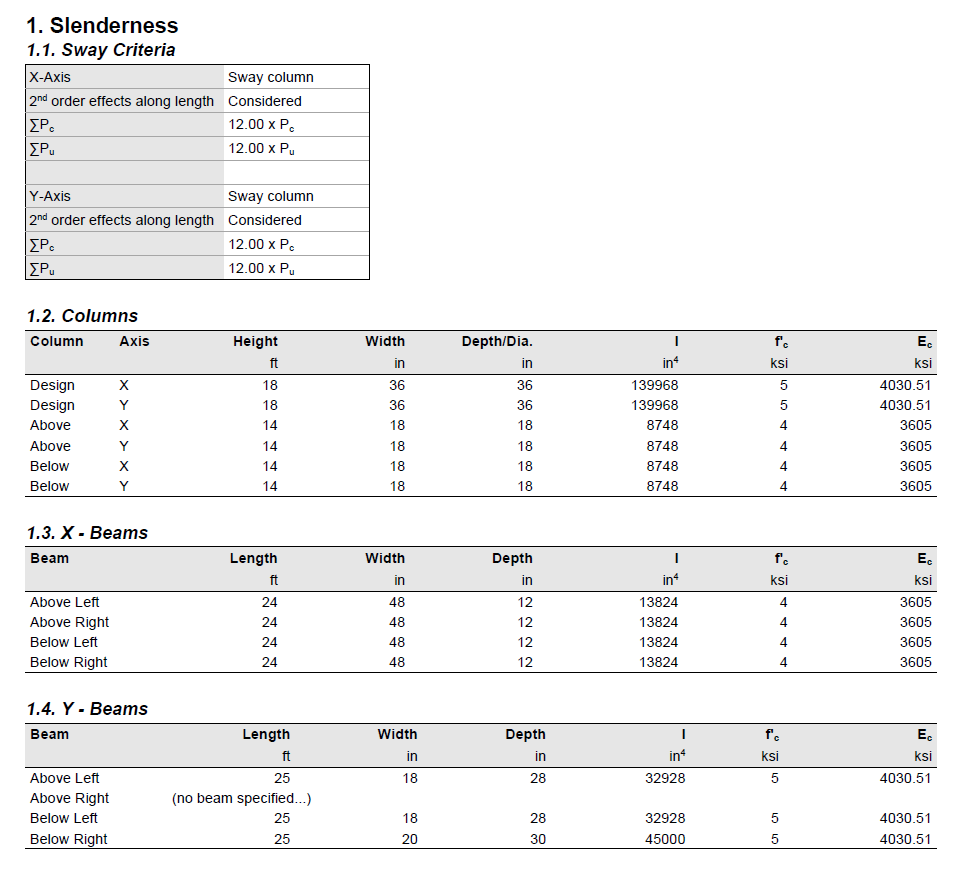
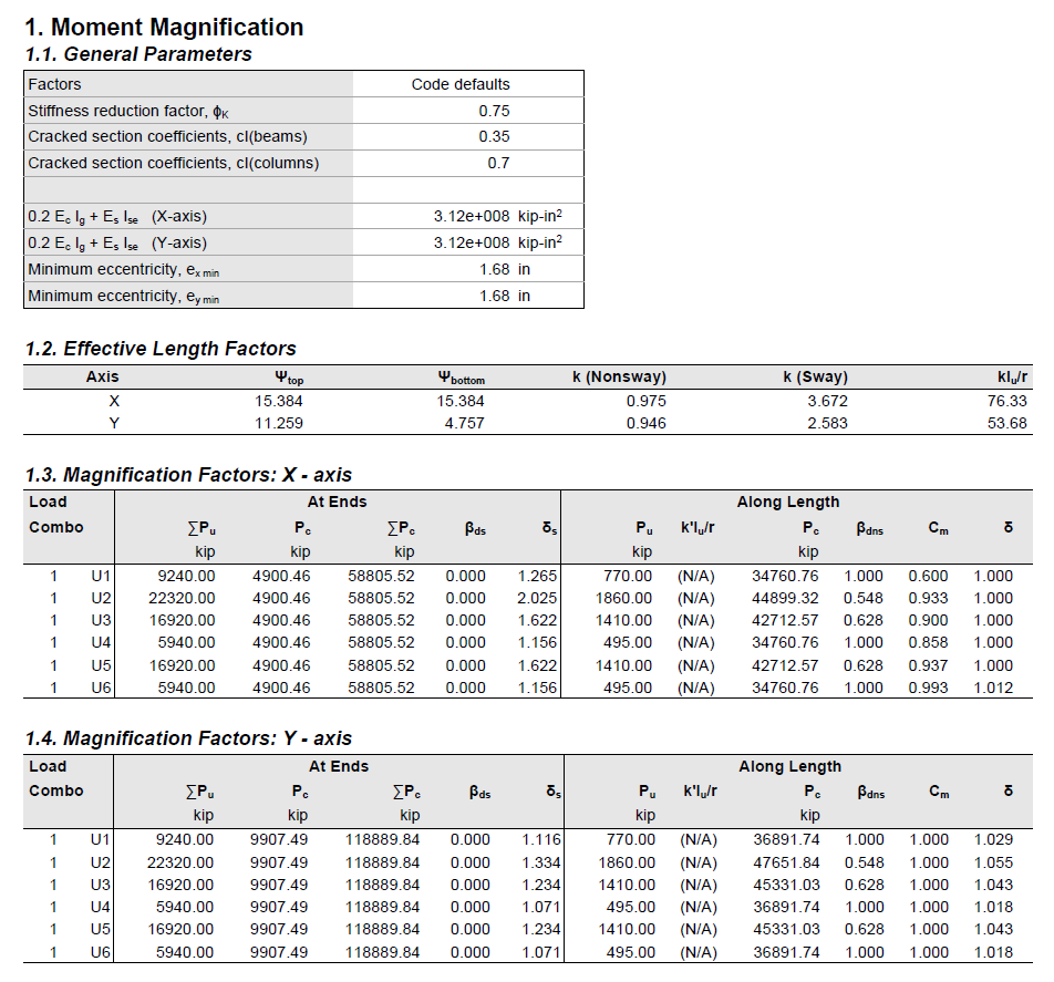
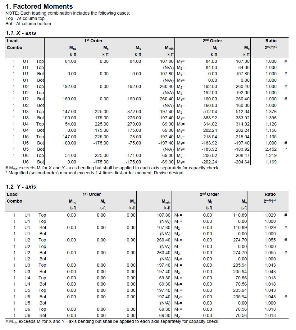
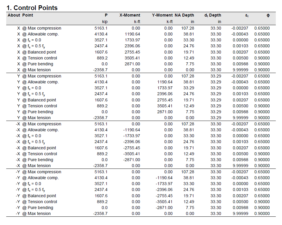
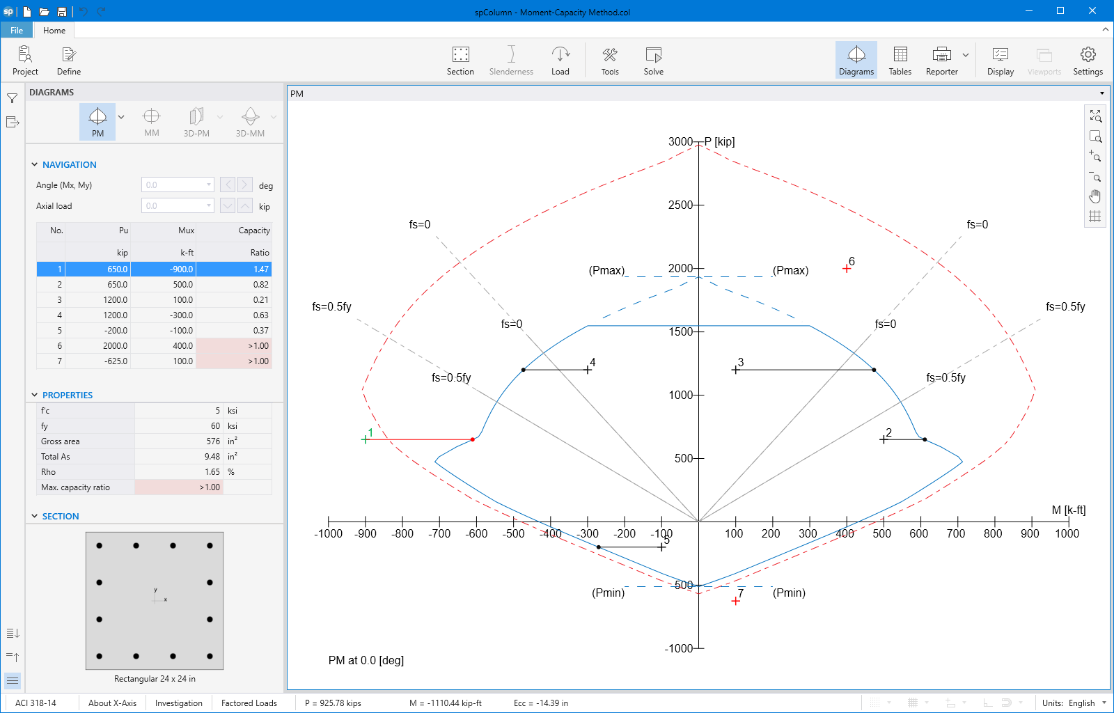
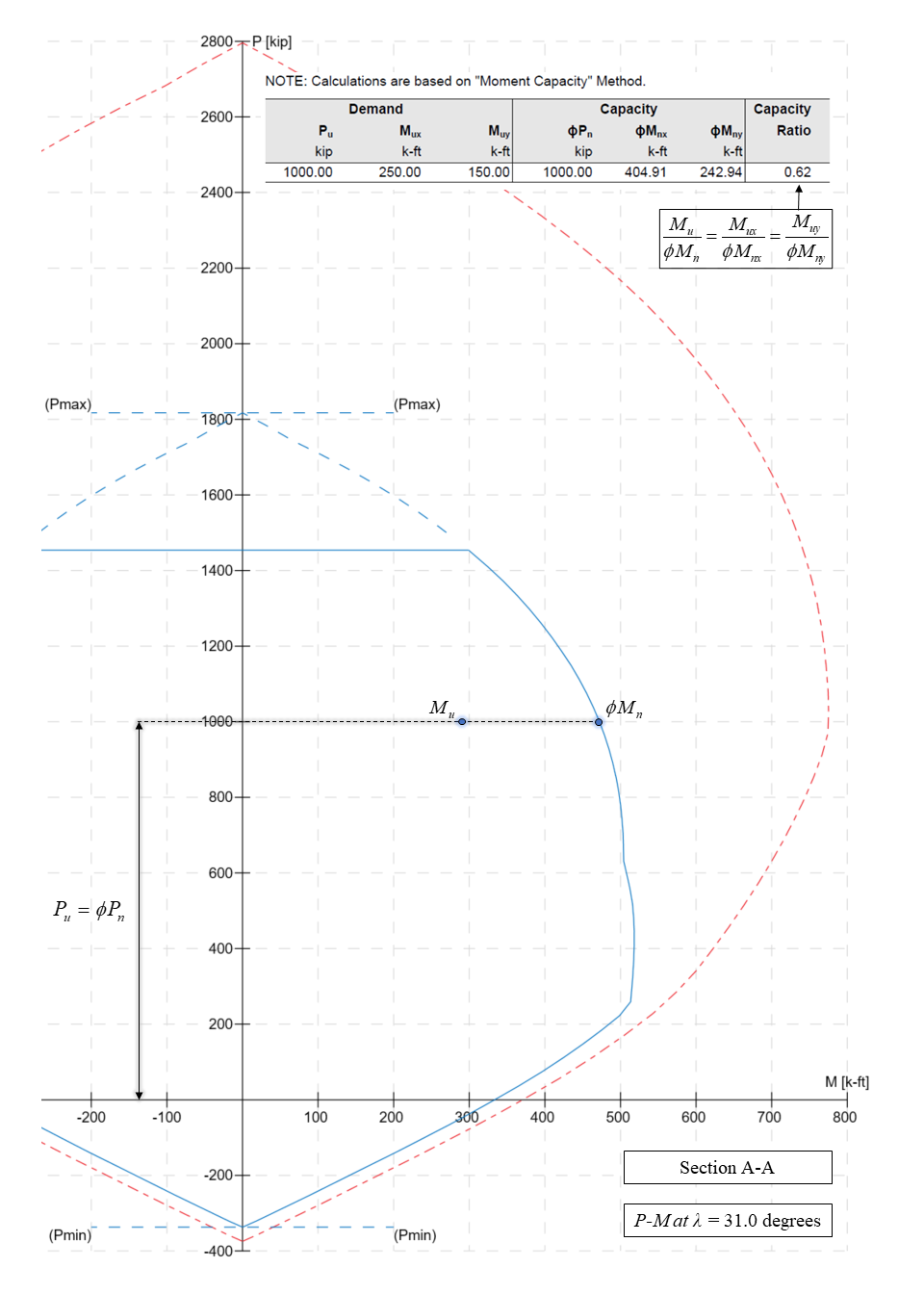
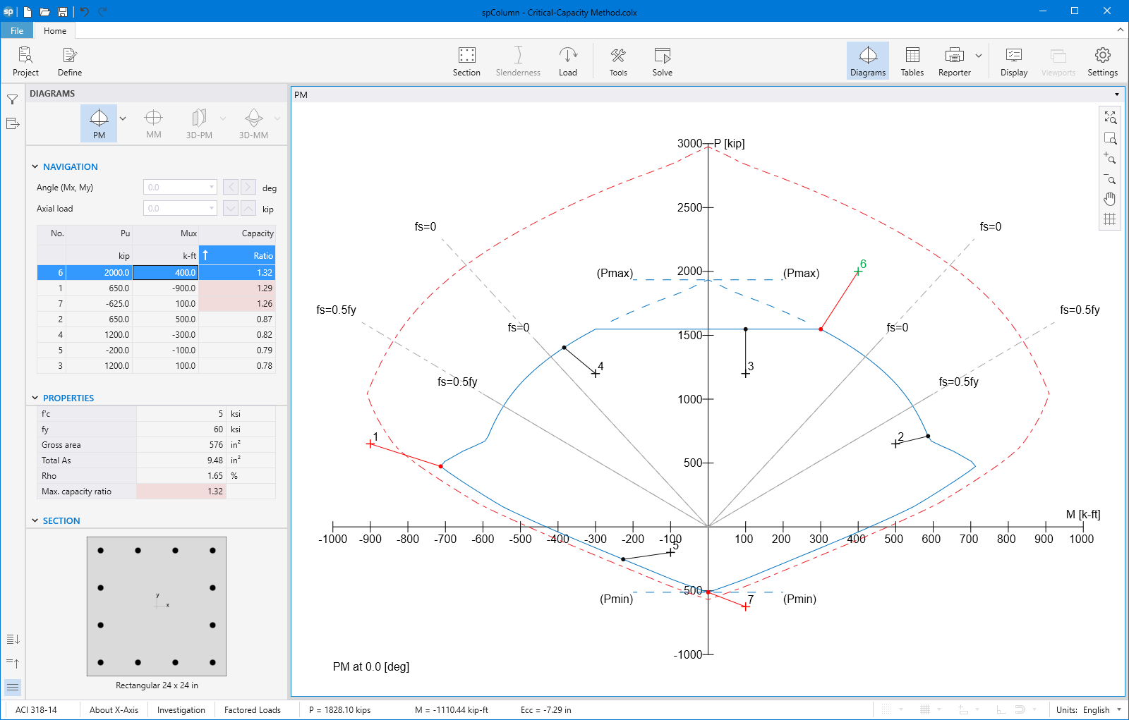
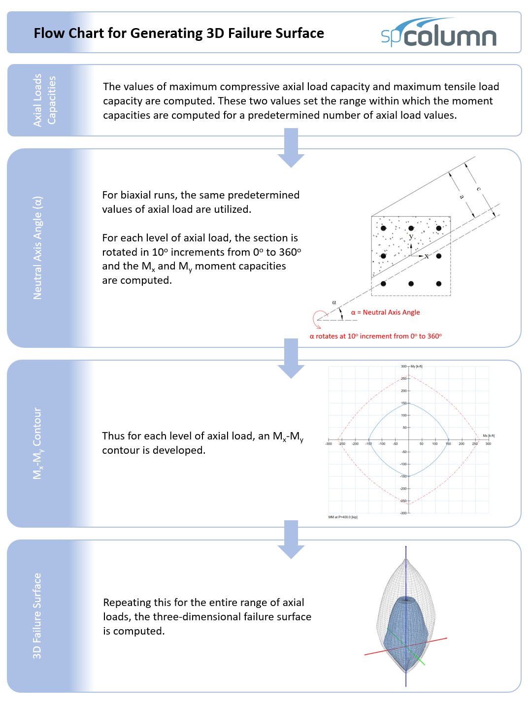
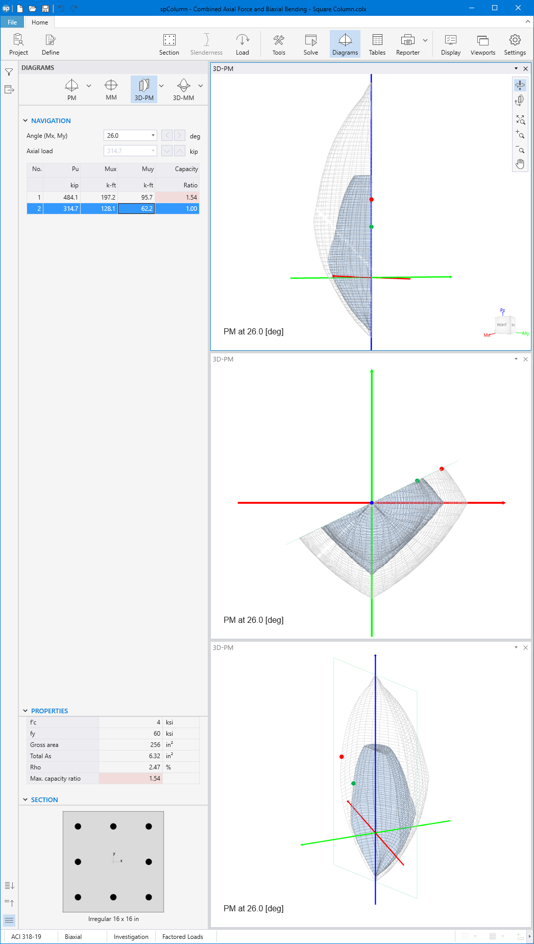
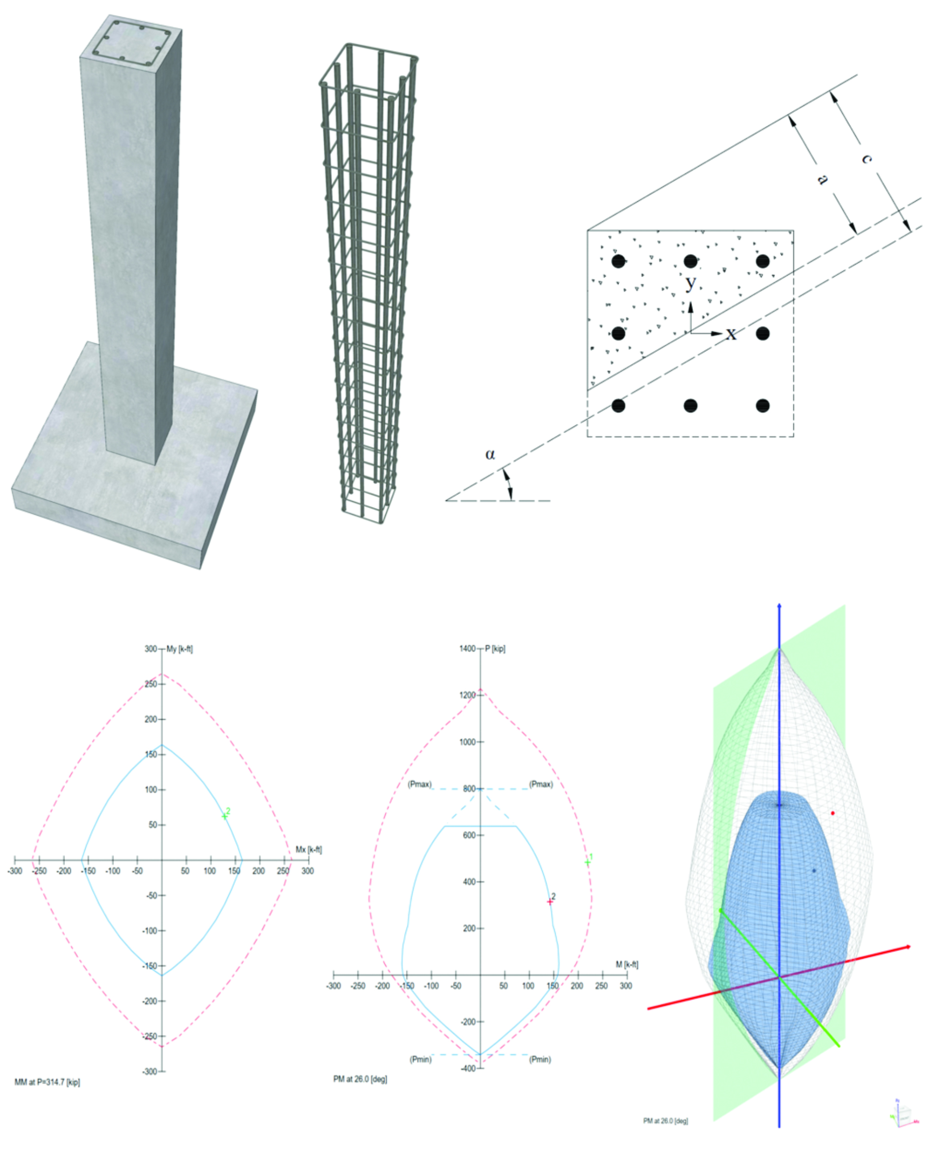
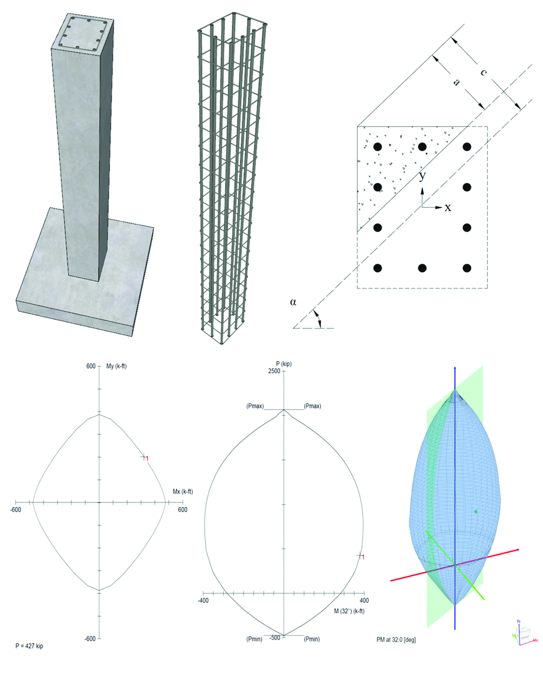
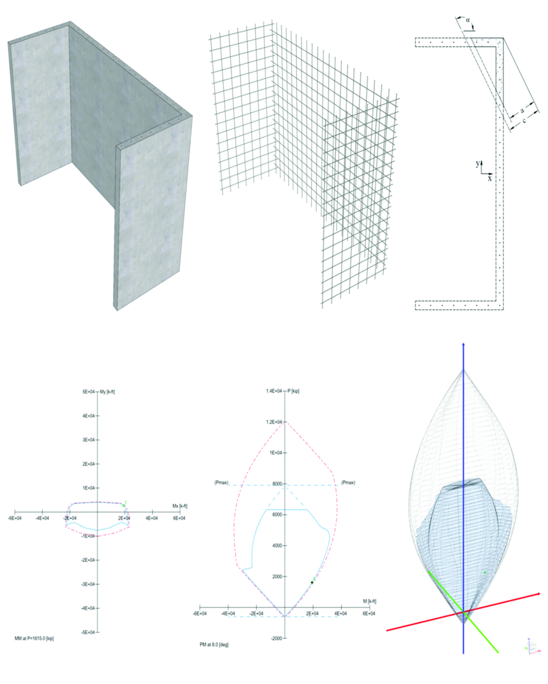
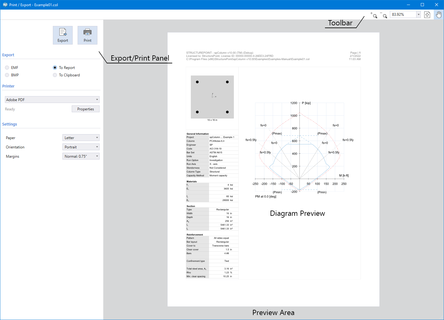
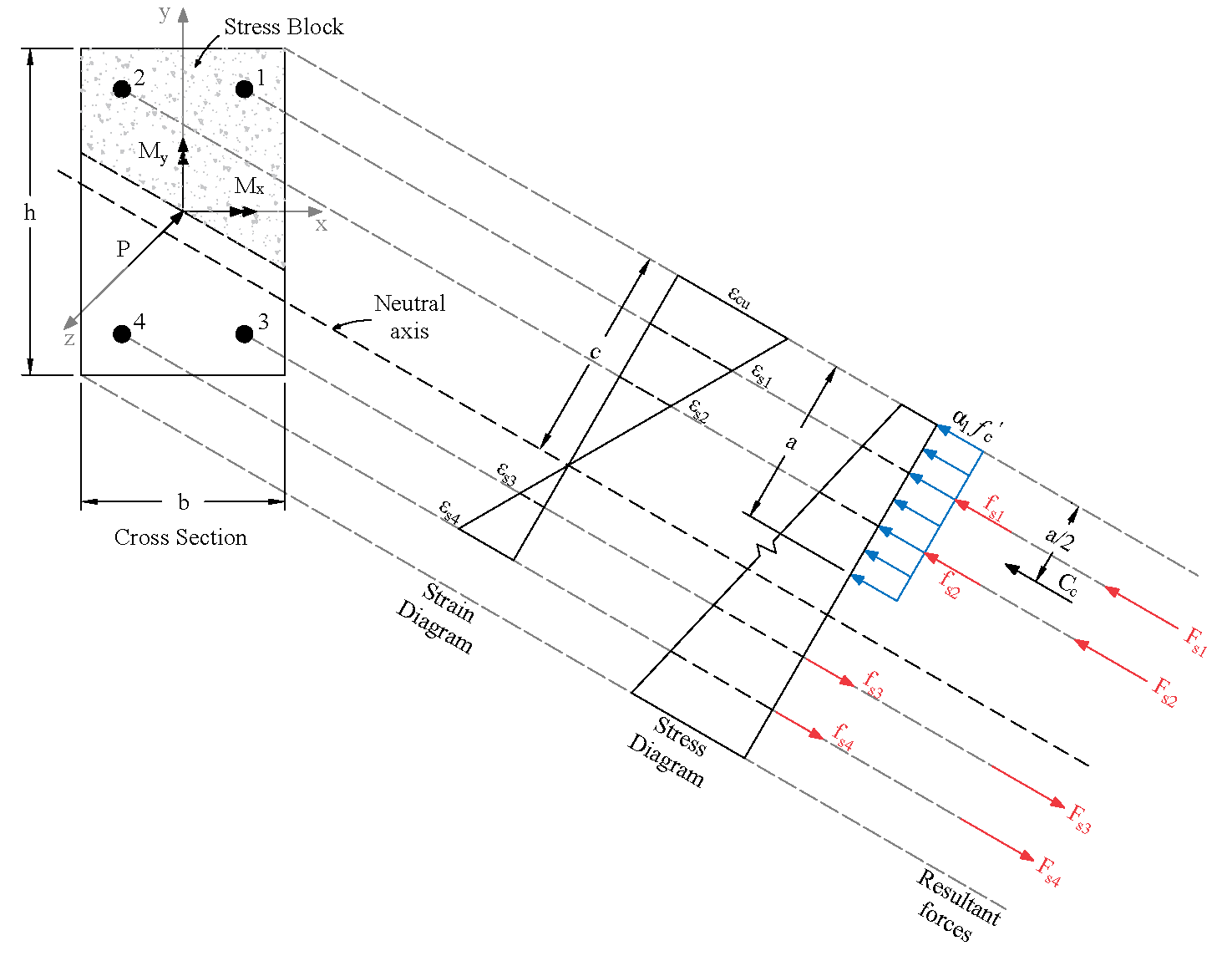
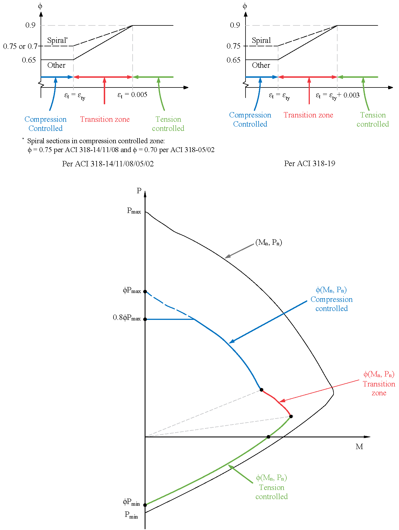
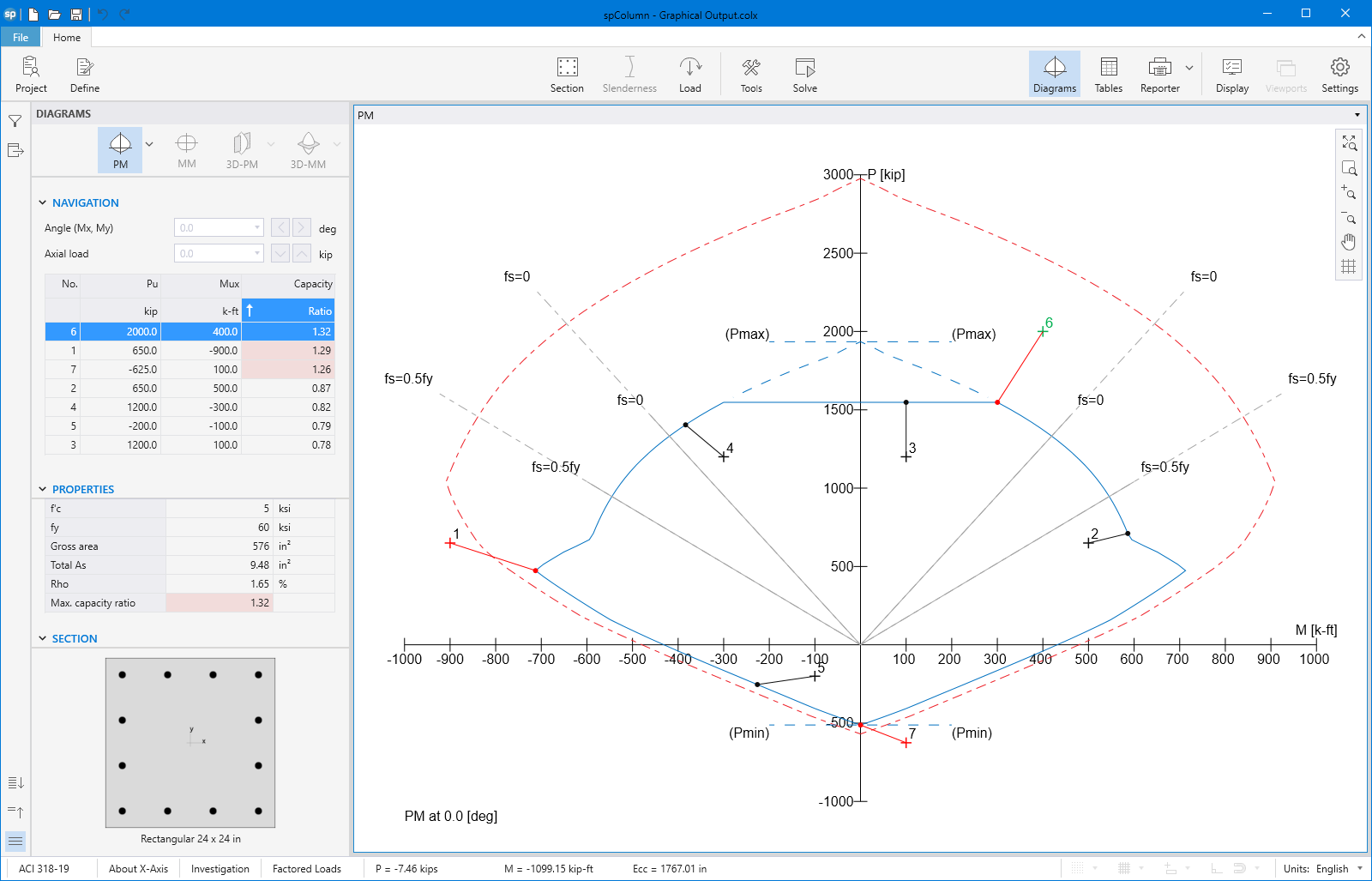
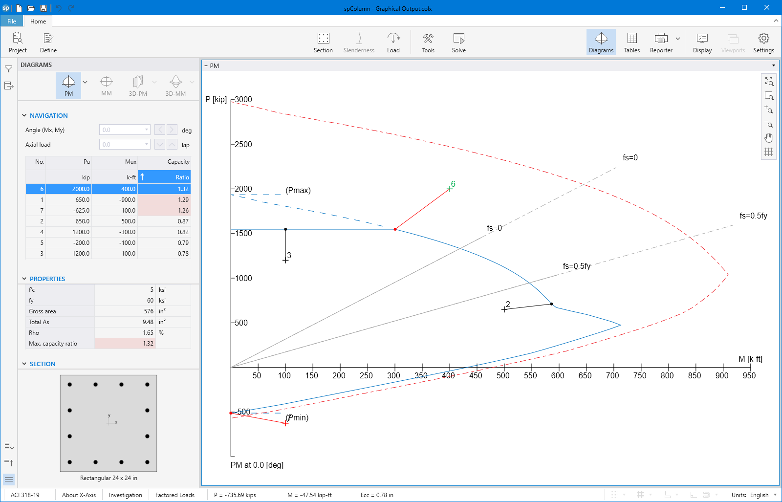
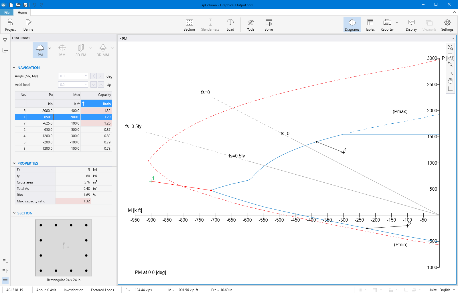
spColumn computes the interaction diagram (uniaxial runs) or the three-dimensional failure surface (biaxial runs) of the input section. The values of maximum compressive axial load capacity and maximum tensile load capacity are computed. These two values set the range within which the moment capacities are computed for a predetermined number of axial load values.
- For uniaxial runs, positive and negative moment capacities about only the selected axis are computed. Moment capacities about the orthogonal axis are ignored. To compute the moment capacity at a certain level of axial load, the neutral axis angle is held constant, parallel to the selected axis. The neutral axis depth is adjusted to arrive at the desired axial load capacity. This is done for all the predetermined values of axial load.
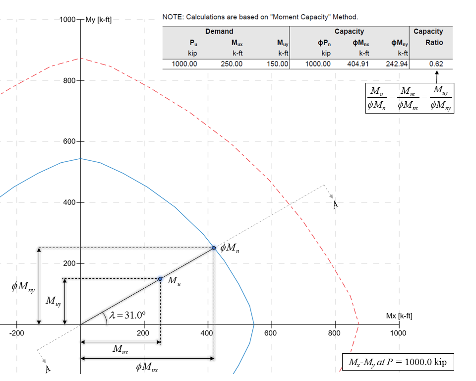
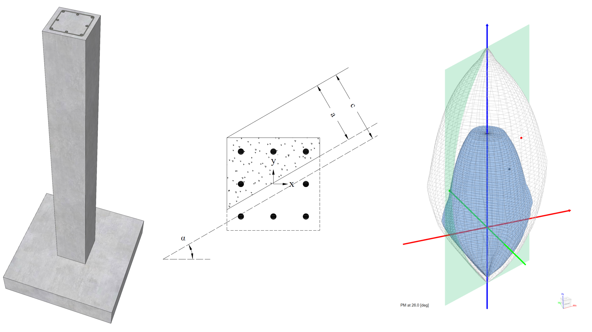
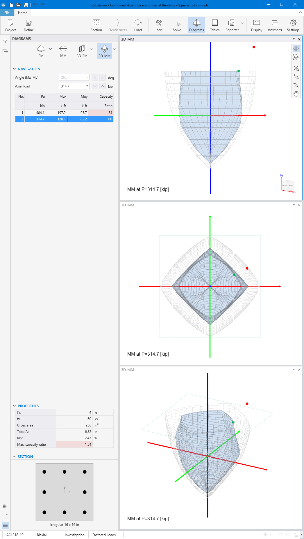
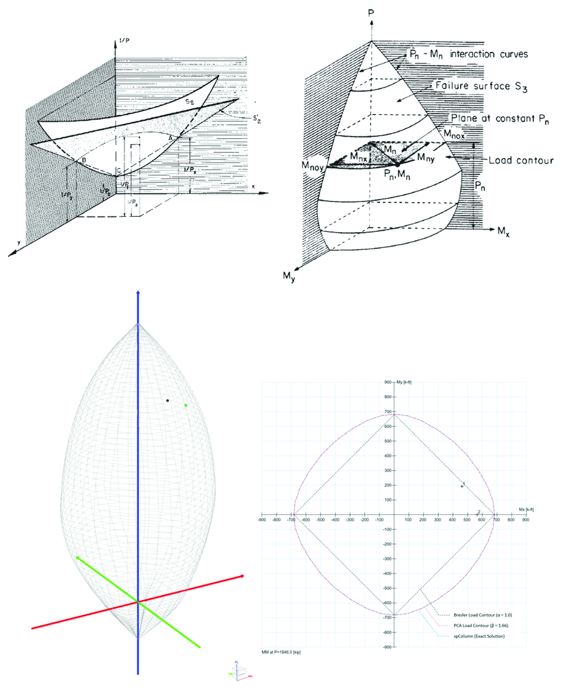
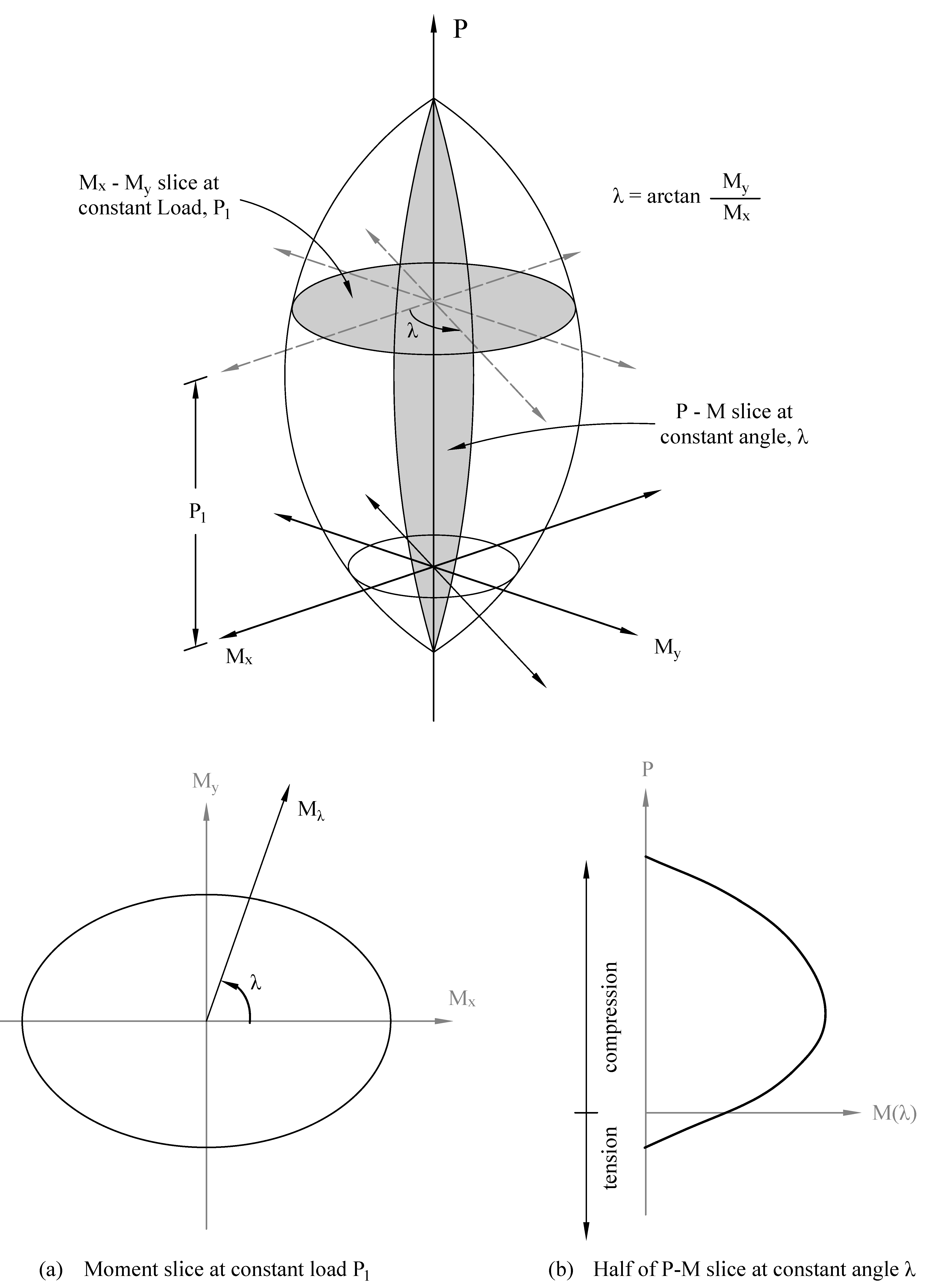
- For biaxial runs, the same predetermined values of axial load are utilized. For each level of axial load, the section is rotated in 10-degree increments from 0 degrees to 360 degrees and the Mx and My moment capacities are computed. Thus for each level of axial load, an Mx-My contour is developed. Repeating this for the entire range of axial loads, the three-dimensional failure surface is computed. A three-dimensional visualization of the resulting entire nominal and factored failure surface is provided to support enhanced understanding of section capacity.
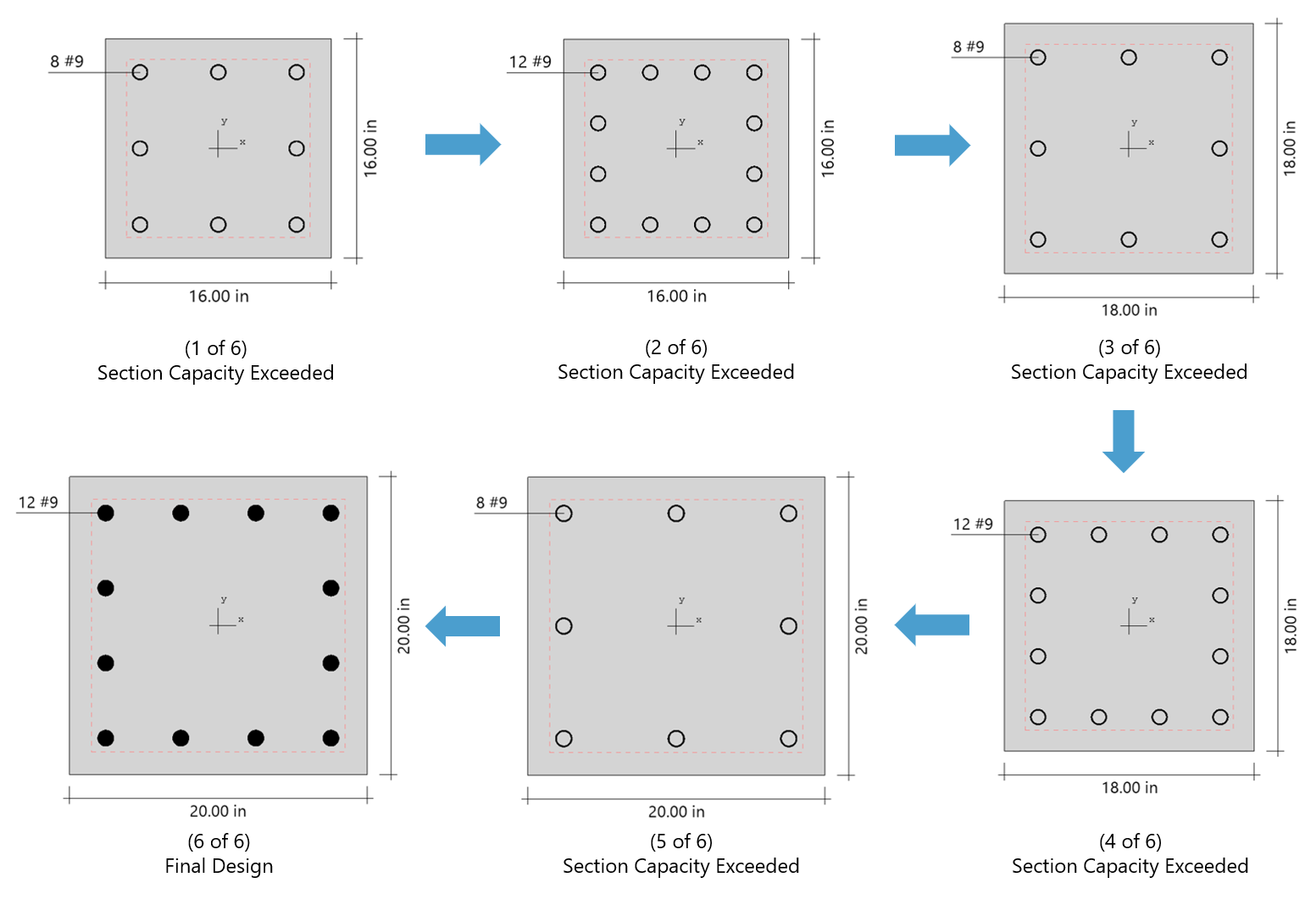
Based on the specified minimum, maximum and increment specified for the section and the reinforcing bars, the program selects the smallest section with the least amount of reinforcement for which the load-moment capacity exceeds the appplied loads. Depending on the design criteria the user selects, the least amount of reinforcement the program searches for means either the smallest number of bars or the smallest steel area.
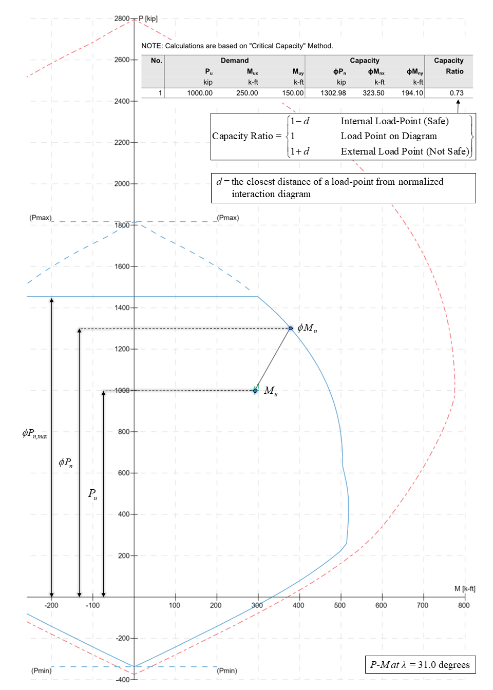
The program can compute the section demand capacity ration in one of the two available methods, namely, Moment-Capacity Method and Critical-Capacity Method.
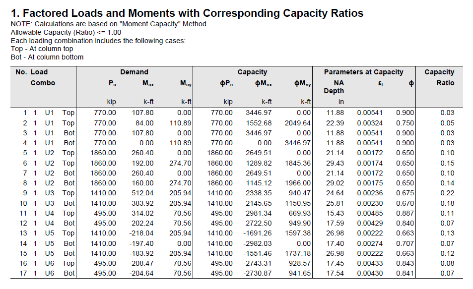
Moment-Capacity Method calculates the section capacity as the ratio of moment demand, Mu to moment capacity, ΦMn. When a unique value of ΦMn cannot be calculated for a given load point, this method gives the capacity ratio as "> 1" or "< 1" depending on the location of the point.
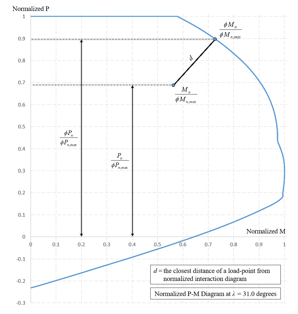
Capacity Ratio Per Moment-Capacity MethodCritical-Capacity Method calculates the section capacity based on the closest distance to a load-point from the normalized interaction diagram. More information on normalized interaction diagram and calculation of the closest distance, d, can be found in spColumn Manual.
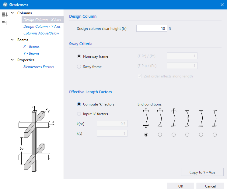
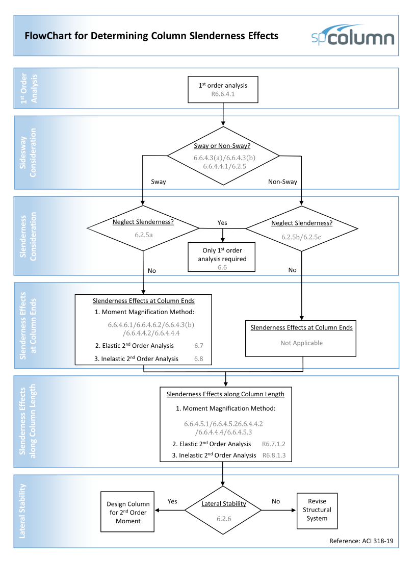
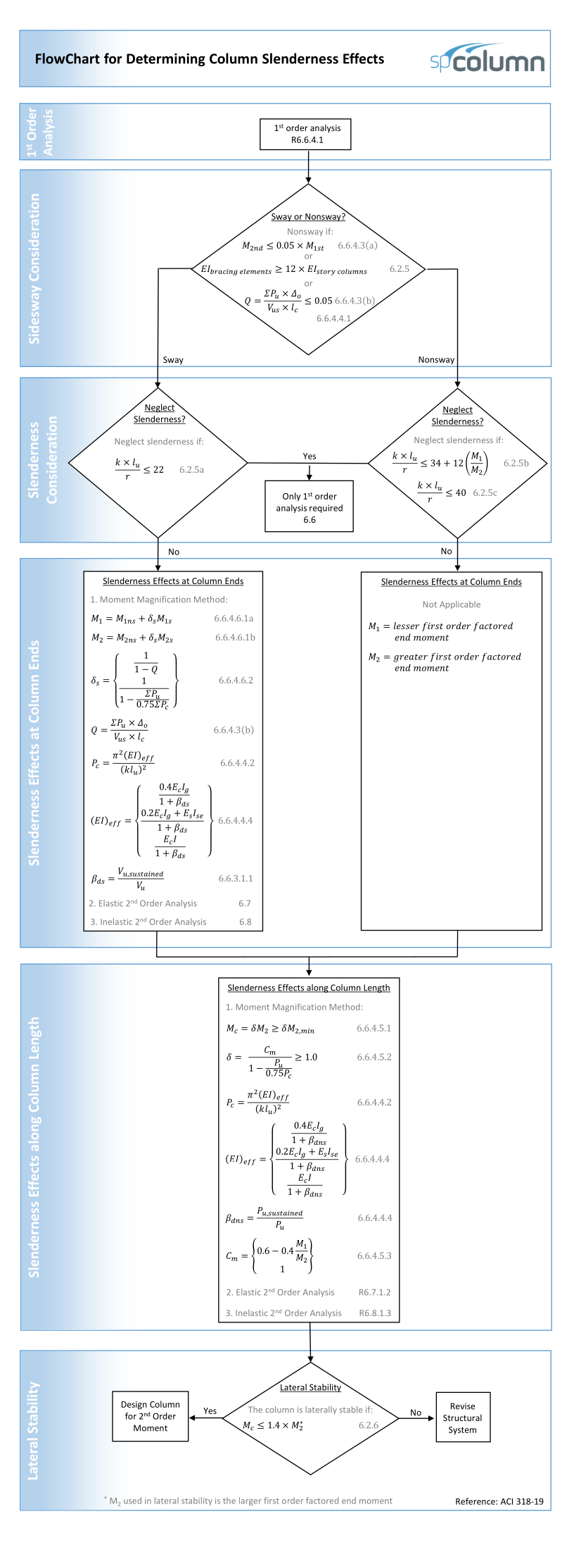
Capacity Ratio Per Critical-Capacity MethodColumn slenderness is expressed in terms of its slenderness ratio klu/r, where k is an effective length factor (dependent on rotational and lateral restrains at the ends of the column), lu is unsupported column length, and r is the radius of the gyration of the column cross-section. In general, a column is slender if its aplicable cross-sectional dimension is small in comparison to its length.
Slenderness effects producing magnified moments through moment magnification procedure (ACI 318 and CSA A23.3) can be considered both for design and investigation of sections in lieu of complicated and time consuming 3D analytical models.
In most building design calculations, all building columns may be subjected to biaxial bending (Mx and My) due to lateral effects and unbalanced moments from both directions of analysis. This requires an investigation of the column P-Mx-My interaction diagram in two directions simultaneously (axial force interaction with biaxial bending).
Generating the three-dimensional failure surface (interaction diagram) for a column section subjected to a combined axial force and biaxial bending moments is tedious and challenging for engineers. The use of a computer aid can save time and eliminate errors.
StructurePoint's spColumn program can quickly, simply and accurately generate the three-dimensional failure surface (interaction diagram) for all commonly encountered column, beam or wall sections in addition to highly complex and irregular cross-sections.
Software
spColumn v10.20spMats v10.50spWall v10.20spSlab v10.00spBeam v10.00spFrame v1.50MaintenanceNetwork LicensingDownload & Buy
Buy Now! Download Trial Shopping Cart Pay Invoice
![Mx-My Diagram [Biaxial Runs Only]](/images/04_Mx-My.png)
![Mx-My Diagram [Biaxial Runs Only]](/images/05_3D.png)
