


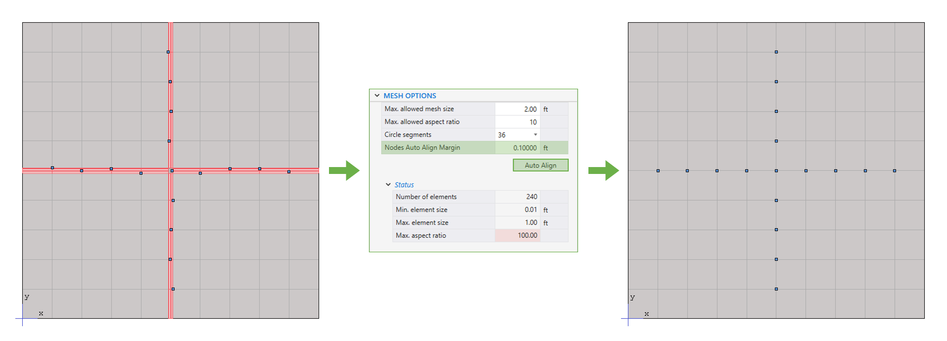
The finite element method is used in spMats for analysis of foundation slabs. During analysis, spMats converts the object-based model into a finite element model. The user defines the mesh used in the analysis by inputting maximum allowed mesh size and maximum allowed aspect ratio. Additional meshing is automatically introduced at slab boundaries, columns, piles, and nodes with assigned properties such as restraints, and point loads.
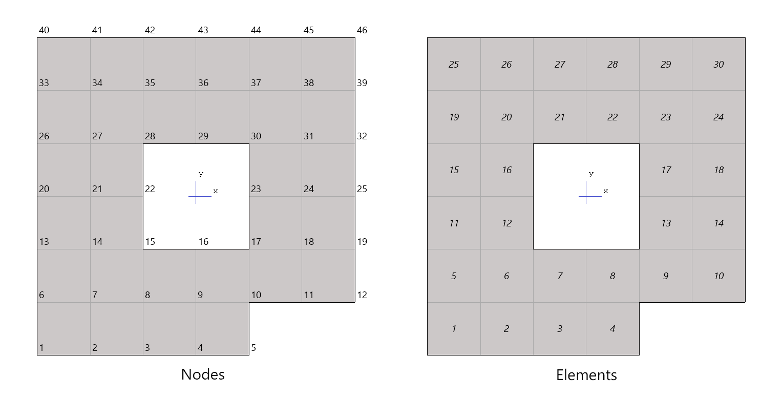
All nodes and members are numbered from left to right (in the positive X-direction) and from bottom to top (in the positive Y-direction).
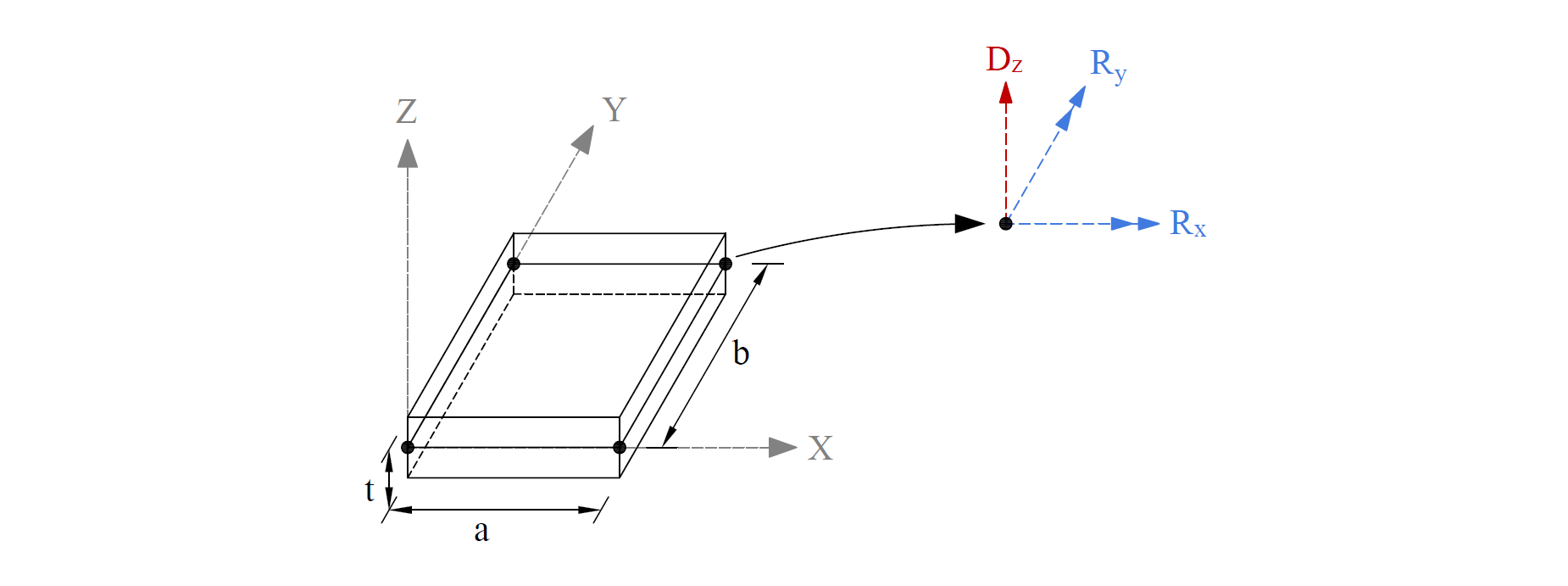
The rectangular plate finite element used in spMats has four nodes at the corners and three degrees of freedom (Dz, Rx and Ry) per node. This element considers the thin plate theory, which makes use of the Kirchhoff hypotheses.
The model can be supported by soil assigned to a slab and/or by piles, nodal restraints, nodal springs, and slaved degrees of freedom that can assigned to nodes.
The soil supporting the slab is modeled as a group of linear uncoupled springs (Winkler type) concentrated at the nodes. The soil element is tensionless, weightless, and has one degree of freedom, which is the displacement in the Z direction (Dz).
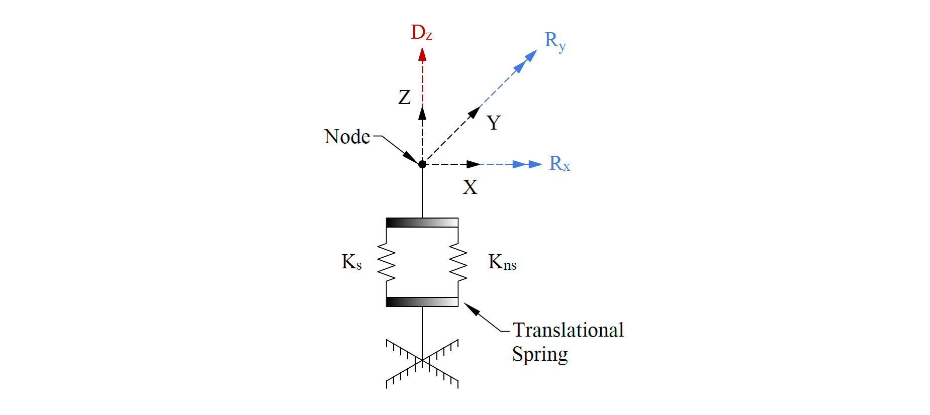
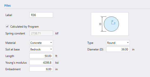
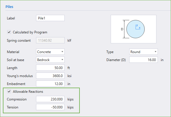
Piles are modeled as springs connected to the nodes of the finite element model. The spring constant, Kp, for a pile is calculated from the formula: Kp = Qu/S where Qu denotes the load applied to the pile and S is the corresponding settlement of the pile.
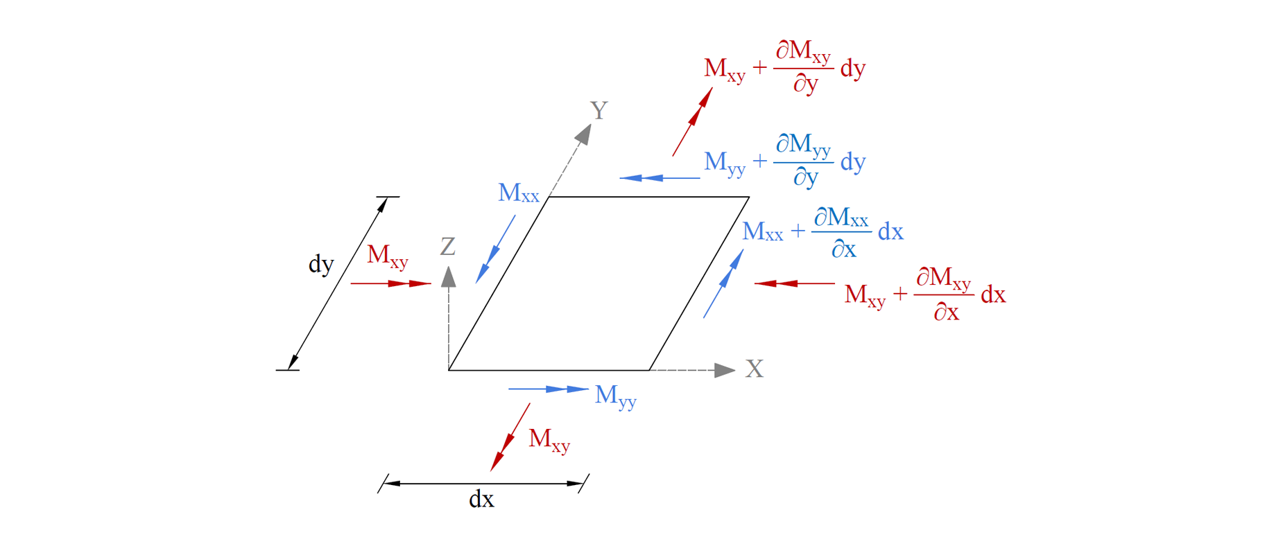
The bending moments, Mxx and Myy, and the twisting moment, Mxy, are computed at the corner nodes of each element. The traditional plate and shell theory convention is that Mxx denotes the moment along (not about) the X-axis and Myy denotes the moment along the Y-axis. Both moments are positive when they produce tension at the top.
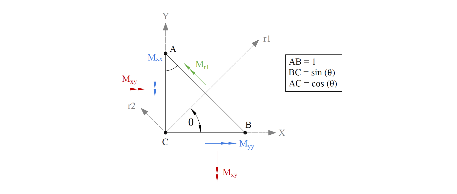
The principal moments, Mr1 and Mr2, and the principal angle, are computed from the general moment transformation equations. Since Mr1 and Mr2 are principal moments, the twisting moment associated with the r1-r2 axes (Mr12) is zero.
The Program utilizes the FEM analysis results in order to calculate the flexural reinforcement according to American (ACI 318) and Canadian (CSA A23.3) design codes. For each element in the analysis model, spMats processes the results to determine applicable design moments are consequently used to calculate the required flexural reinforcement per the selected code edition.
The Principal of Minimum Resistance is used by the program to obtain values for the design moments, which include the effects of the twisting moment. The equivalent design bending moments, Mux and Muy, for the design of reinforcing steel respectively in the X and Y direction are then computed.
The Program reports the area of flexural reinforcement per unit width [in.2/ft (US Customary Units) or mm2/m (Metric Units)]. The total area of reinforcement in an element, then, can be obtained by multiplying the reported area of reinforcement by the width of the element.
For computation of the required flexural reinforcement, the Program offers two options under Slab Design Options:
- Compute required reinforcement based on maximum moment within an element.
- Compute required reinforcement based on average moment within an element.
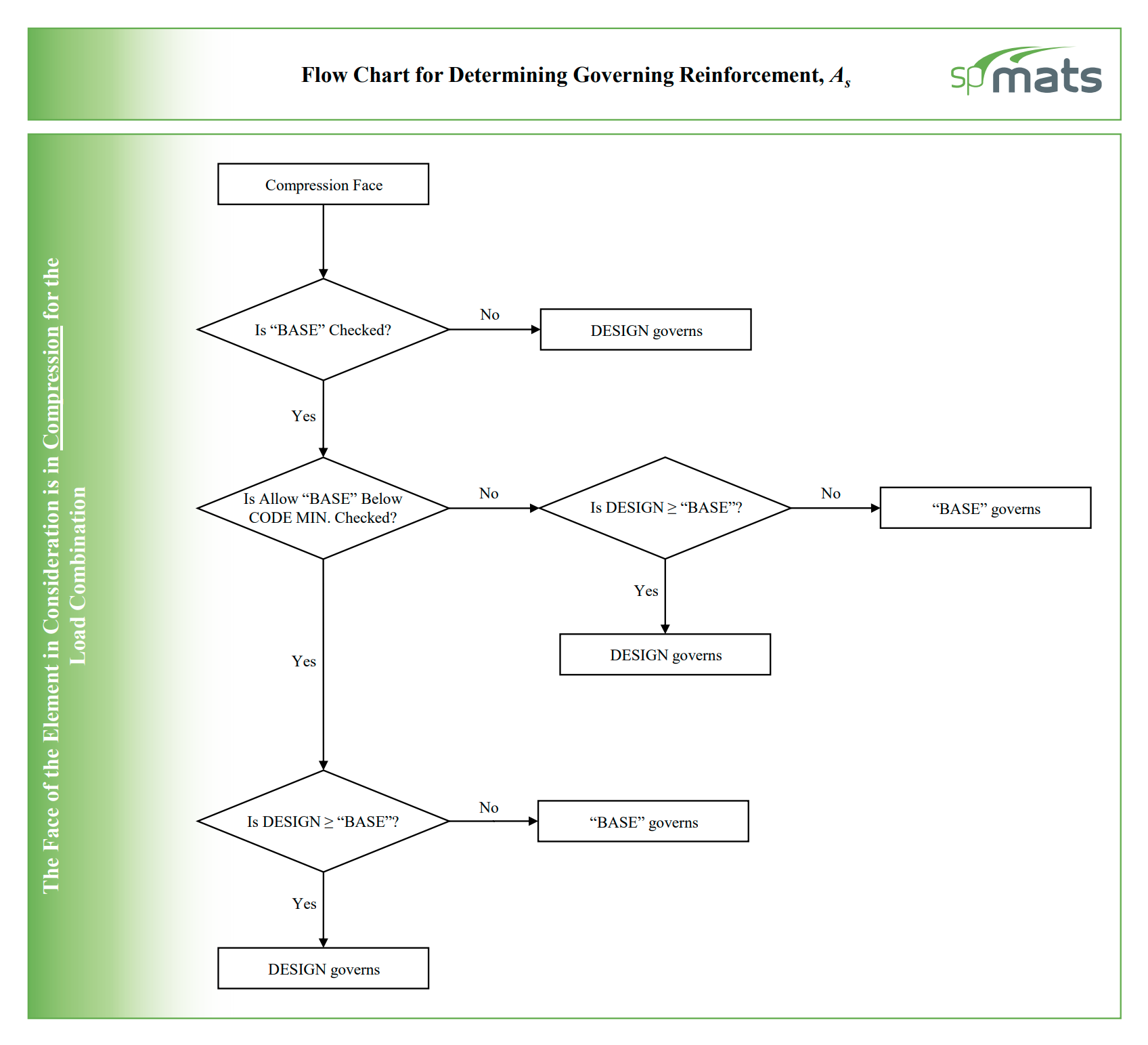
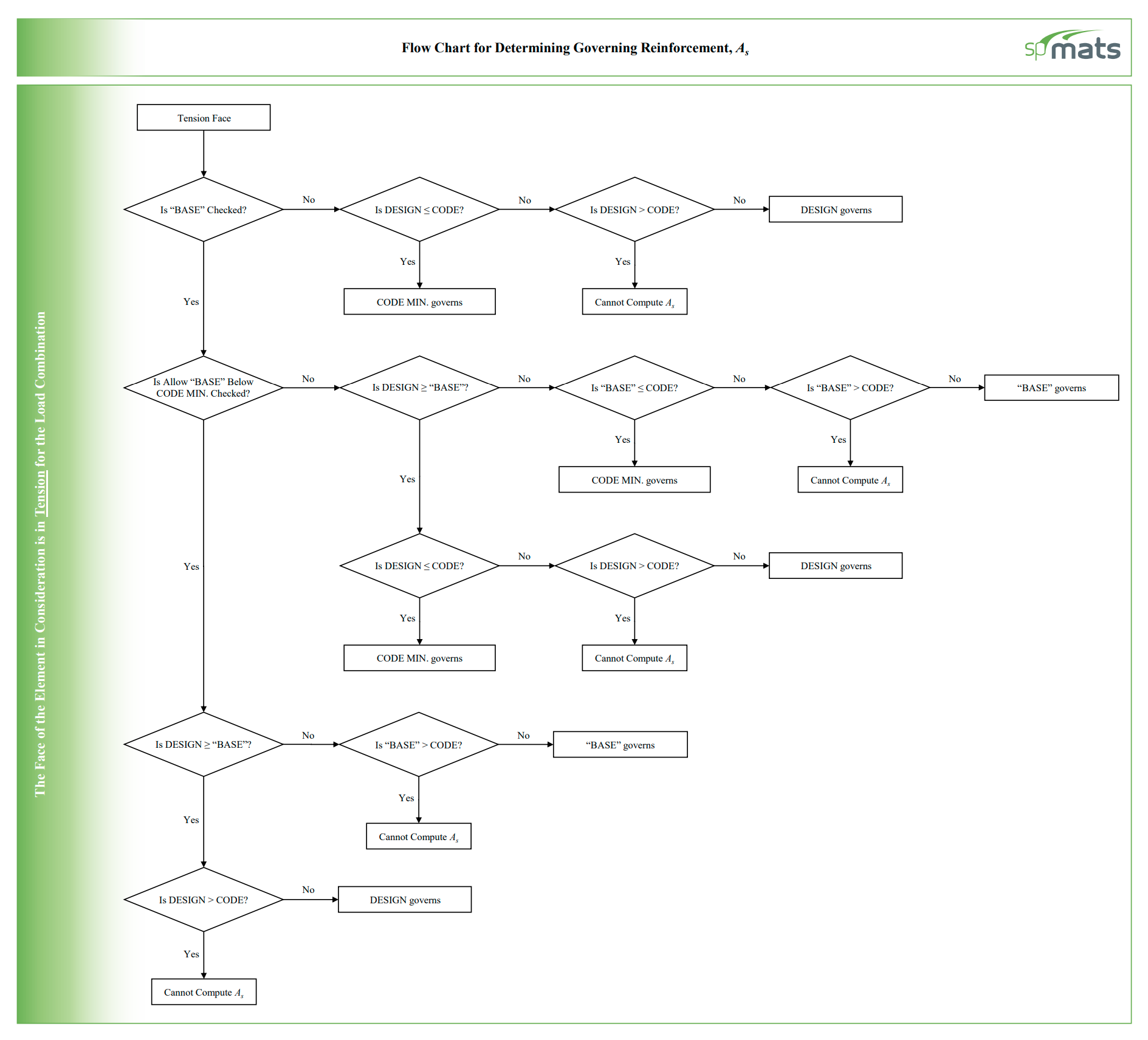
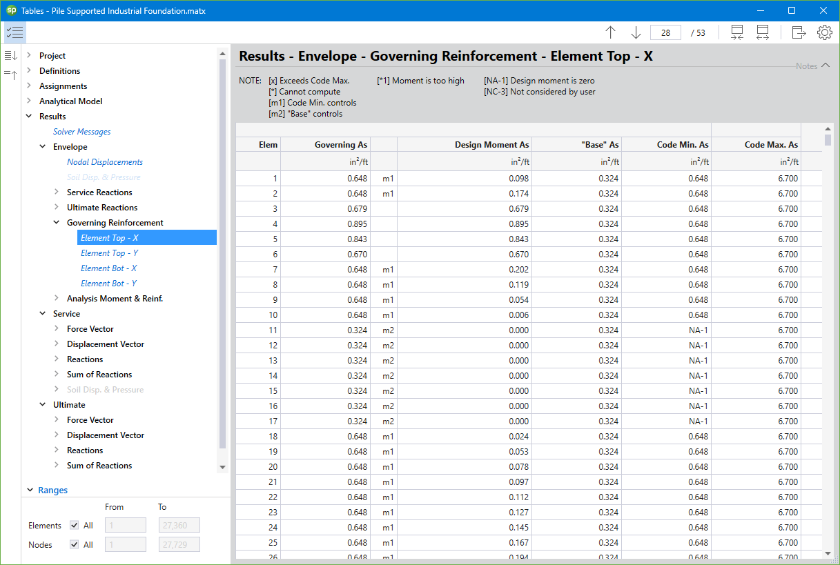
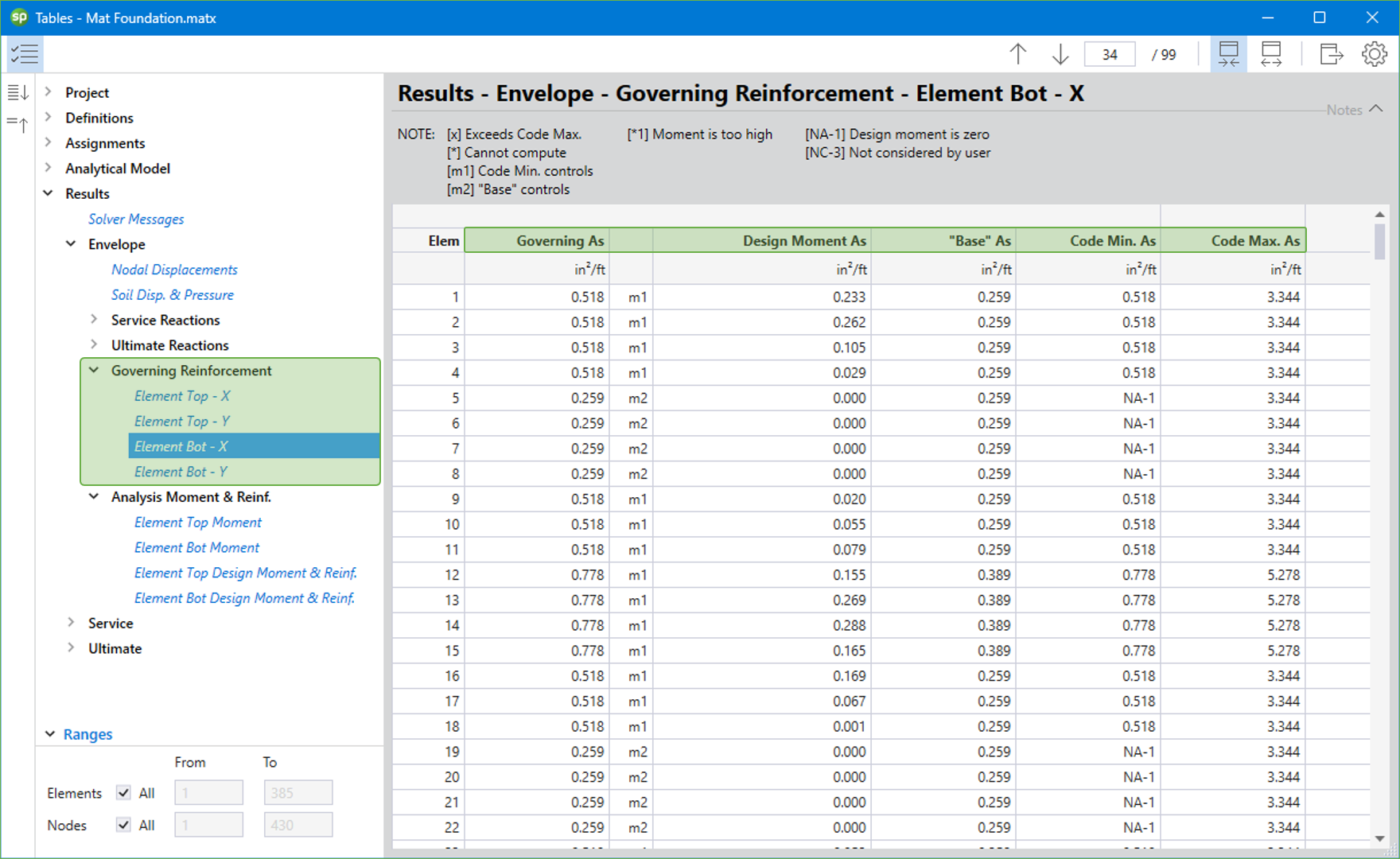
The Program reports the area of flexural reinforcement per unit width based on four criteria, namely, the required reinforcement per analysis result (Design Moment), the minimum and maximum reinforcement ratio requirements as specified by the selected design code (Code Min. & Code Max.), and the user-defined “Base” reinforcement ratio input (“Base”).
The Principal of Minimum Resistance is used by spMats to obtain values for the design moments, which include the effects of the twisting moment. Then, the equivalent design bending moments, Mux and Muy, for the design of reinforcing steel respectively in the X and Y direction are computed.
spMats offers two options for the computation of the required flexural reinforcement under Solve Options. These are:
- Compute required reinforcement based on maximum moment within an element.
- Compute required reinforcement based on average moment within an element.
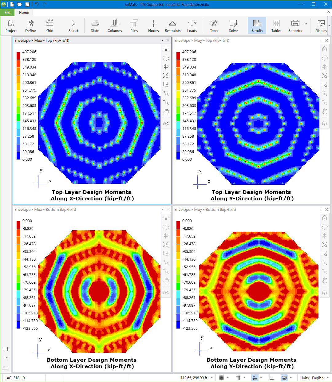
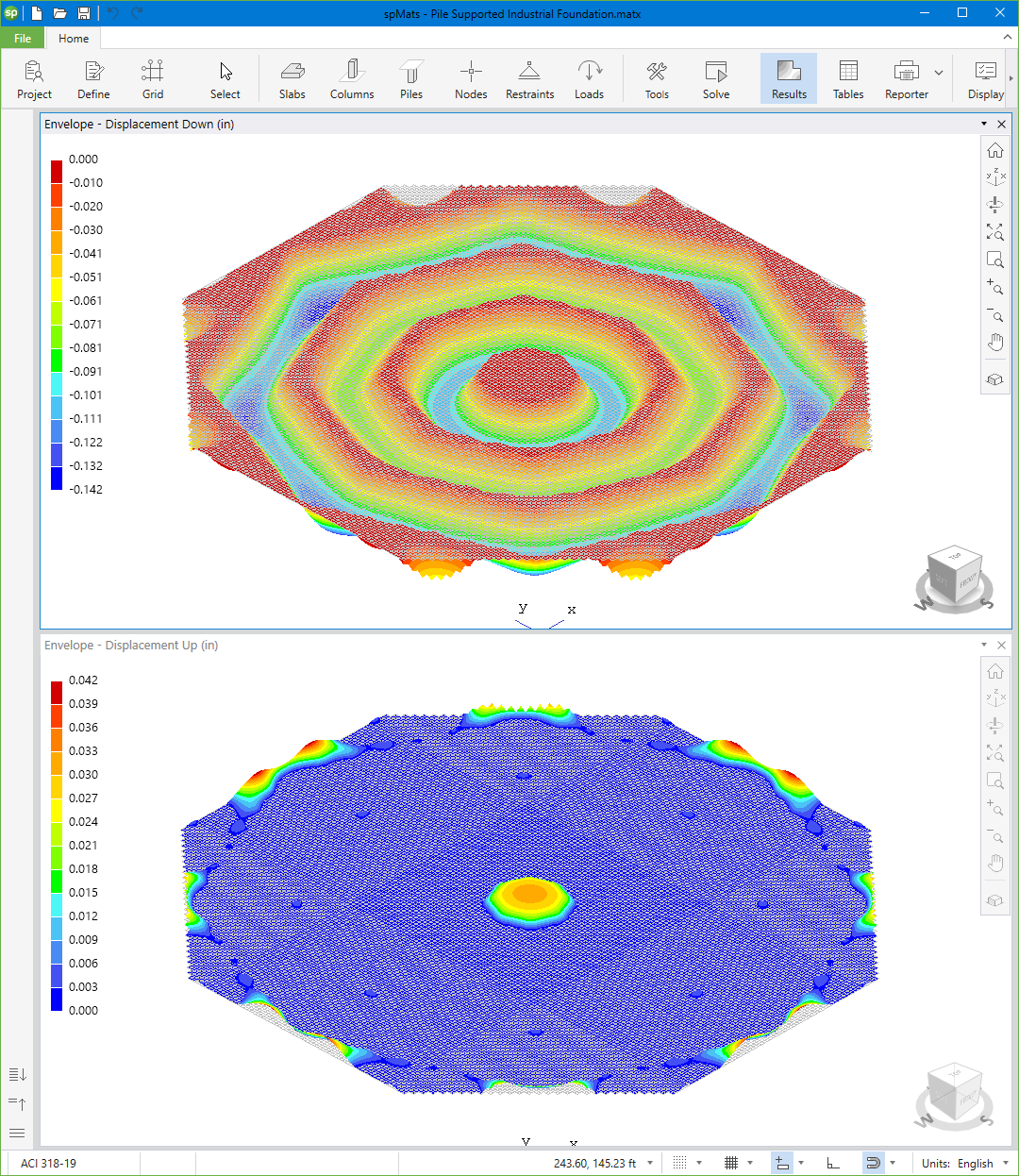
Contour views are used to facilitate the graphical examination of the results by the user. Contour views show the results in three distinct sections, namely, Envelope, Service, and Ultimate.
spMats reports the extreme positive (top layer) and extreme negative (bottom layer) Wood-Armer design bending moments, Mux, and Muy in X- and Y-directions per unit length.
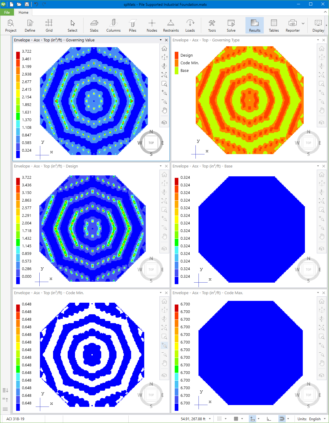
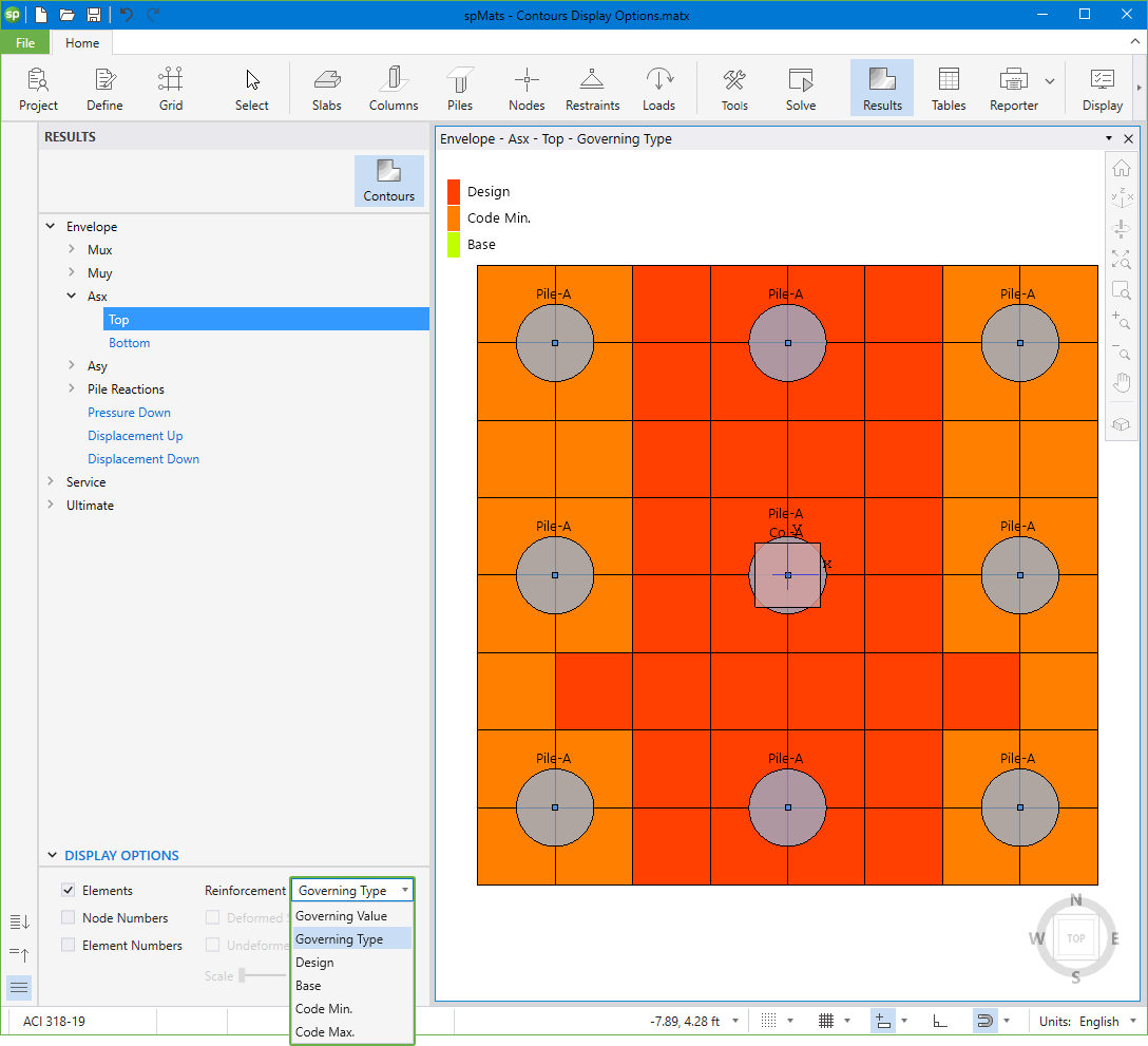
spMats reports the reinforcement quantities per unit length. The default contour shown is for the Governing Value of As. User can also select and view As Top and As Bottom contours for Governing Type, Design, Base, Code Min. and Code Max. reinforcements.
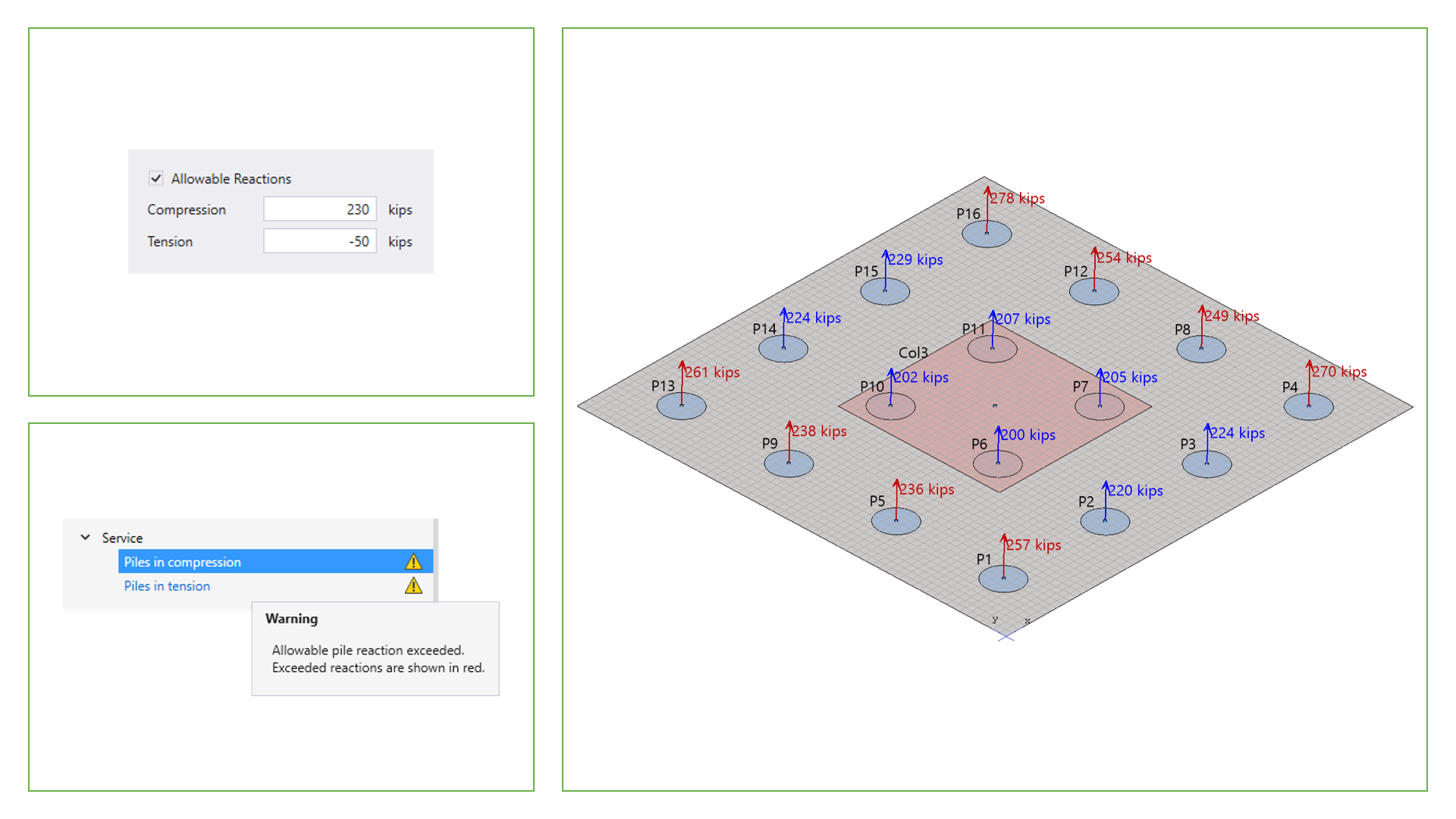
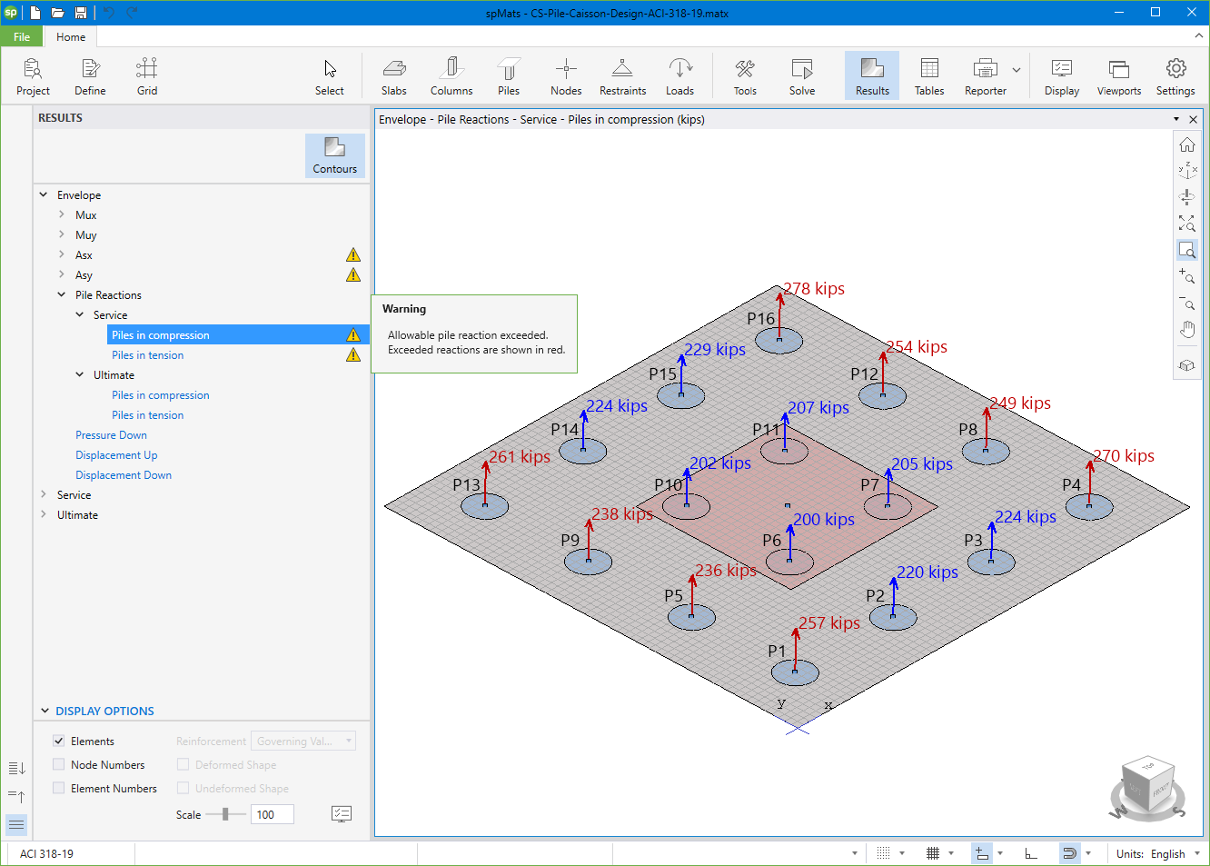
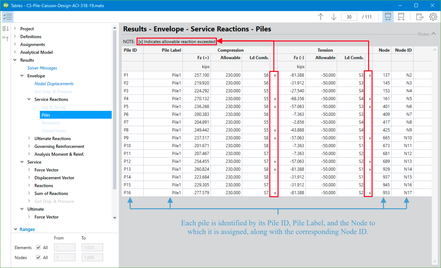
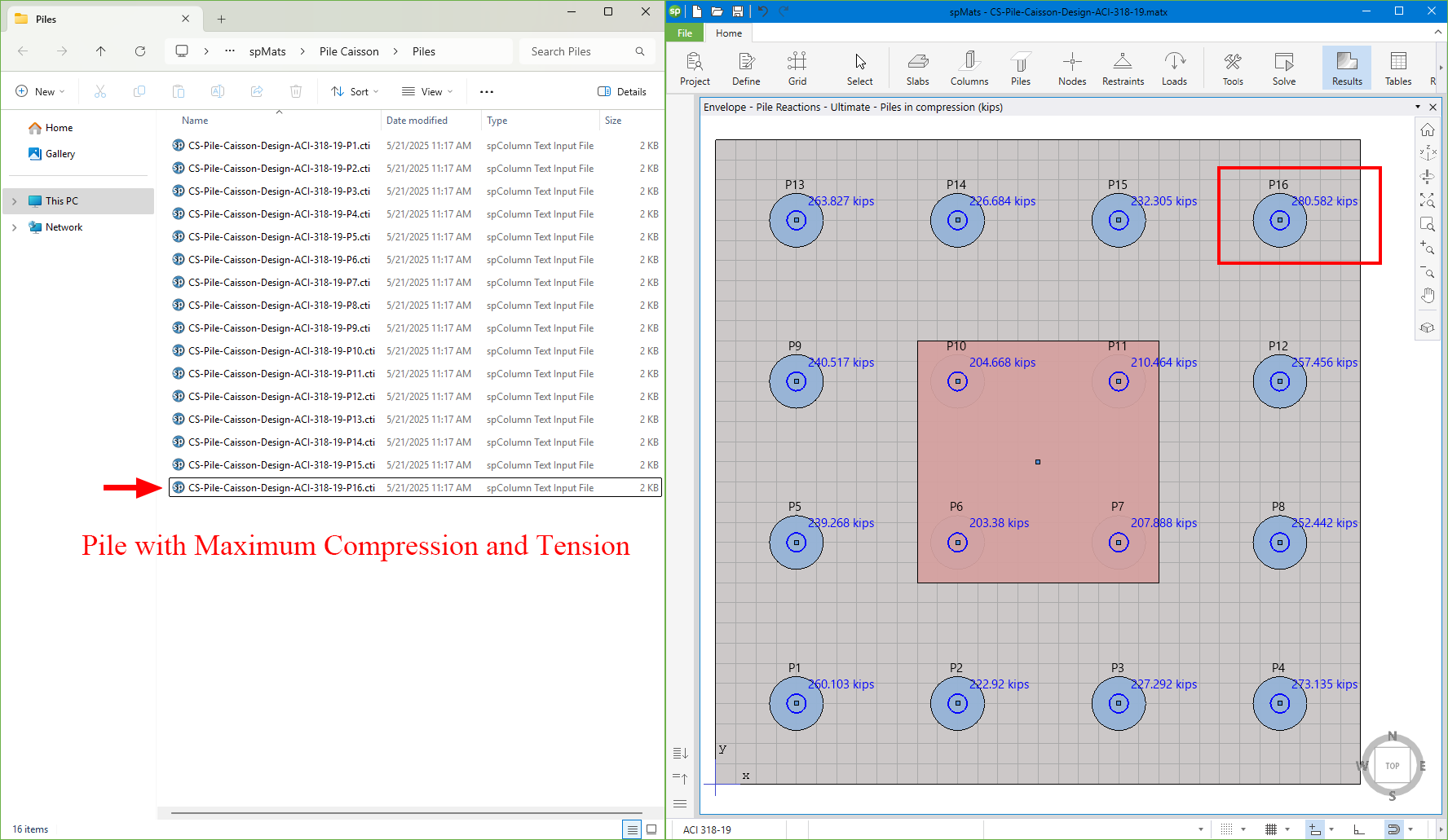
This graphical view displays the envelope results for reactions of Piles in Compression and Piles in Tension under Service and Ultimate load combinations. Pile reactions are represented graphically with directional arrows - upward arrows for compression and downward arrows for tension. When allowable pile reactions are defined by the user, the program will automatically evaluate each pile's reaction against these limits. Pile reactions that do not exceed the allowable values are displayed in blue, while those that exceed are highlighted in red to alert the user. A warning icon will also appear in the Contours tree to indicate that one or more pile reactions exceed the allowable limit. Note that allowable pile reactions, when specified, are only applicable to and compared with the Service pile reactions.
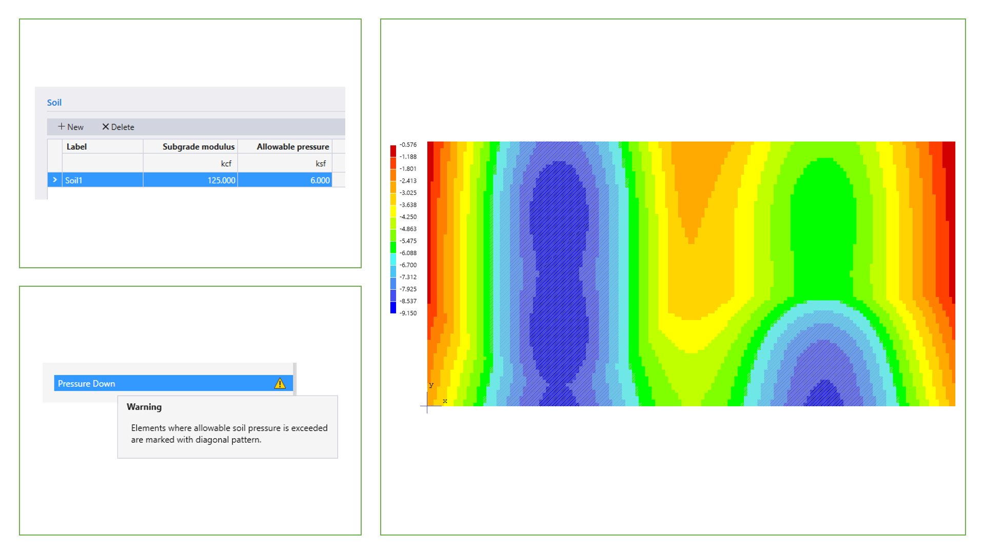
spMats calculates the soil pressures at all four nodes of an element for both service load and ultimate load combinations. The calculated soil pressures are compared with the allowable pressure values during the analysis. If the calculated soil pressure exceeds the allowable pressure specified by the user, the Program displays a warning message when analysis is completed and elements with this condition are indicated in the graphical pressure contours view.
spMats reports displacements, both settlement and uplift, for individual service and ultimate load combinations as well as envelope values. The user may set a maximum allowable service displacement limit.
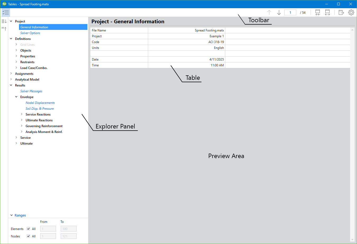
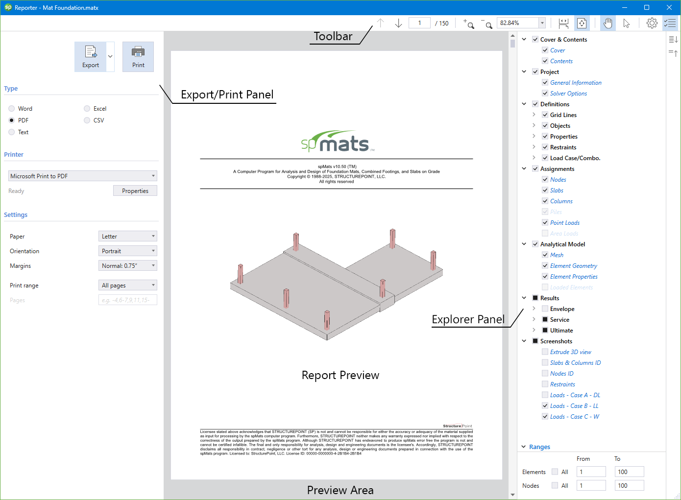
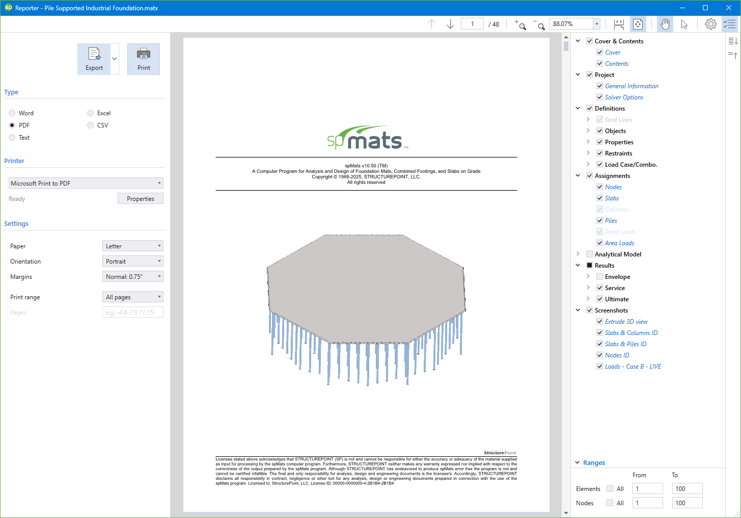
The Tabular output can be found both in the Tables Module and the Reporter Module. The Tables Module may be utilized to view and export the model output at any model development stage. The Reporter Module may be utilized to create, export and print customized reports when the design is finalized. Both modules have the same output sections. The differences being that of the Reporter Module contains the cover & contents, and screenshots sections. The Tables Module contains the Solver Messages section. The tables may be fully or partially output for all or for only selected nodes, and elements.
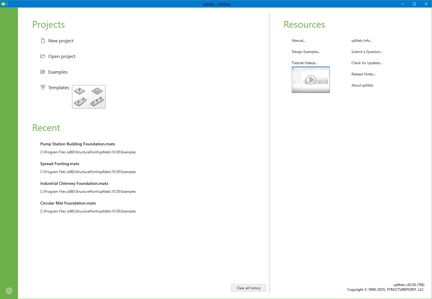
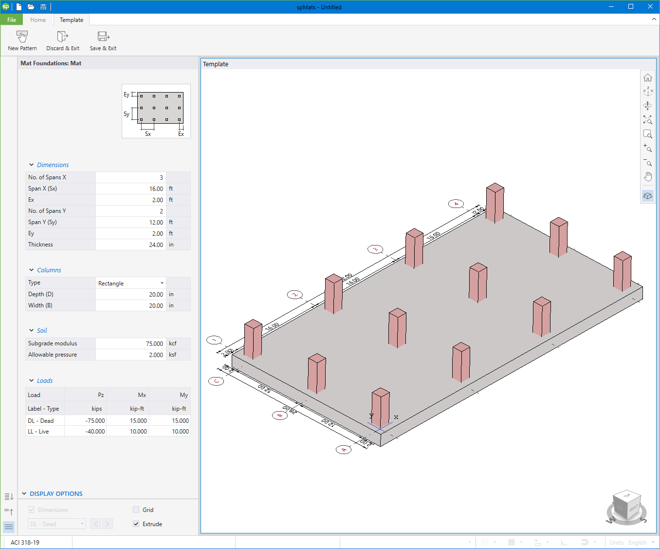
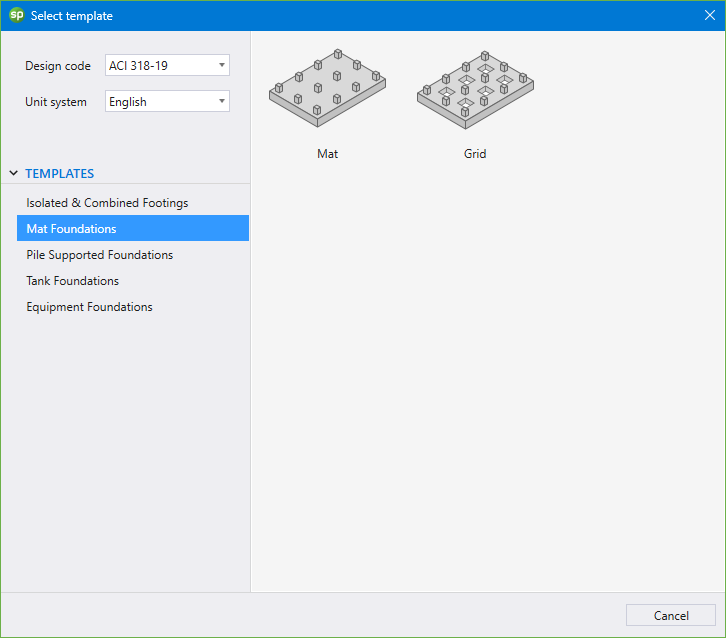
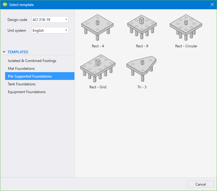
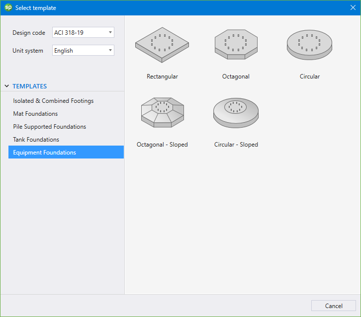
Utilizing Templates is a quick and simple option for new models in spBeam. The user can select from a set of pre-defined templates and edit their properties for simple and quick model generation.
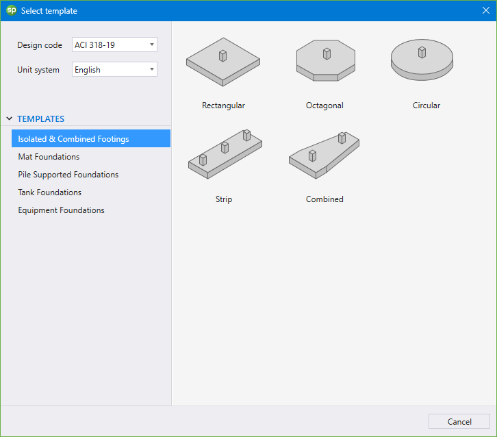
Each template focuses on a particular slab or beam system with a specific loading pattern. The user can edit the geometric dimensions of the system, applied loads, boundary conditions, and material properties. Other system specific options may also be available for some templates.

The latest enhancements in spMats offer advanced tools for modeling and analyzing pile-supported foundations with greater clarity and control.
Users can now define allowable service reactions for piles, enabling visual feedback in the graphical output.
Compression reactions are shown with upward arrows, tension with downward arrows, and reaction values exceeding the specified limits are flagged in red, while compliant values are shown in blue. A warning icon in the interface also highlights any piles that surpass allowable reactions.
In the tabular output, spMats clearly lists each pile's label, Pile ID, assigned node, and Node ID alongside its service and ultimate reactions, providing a comprehensive and traceable summary of foundation behavior.
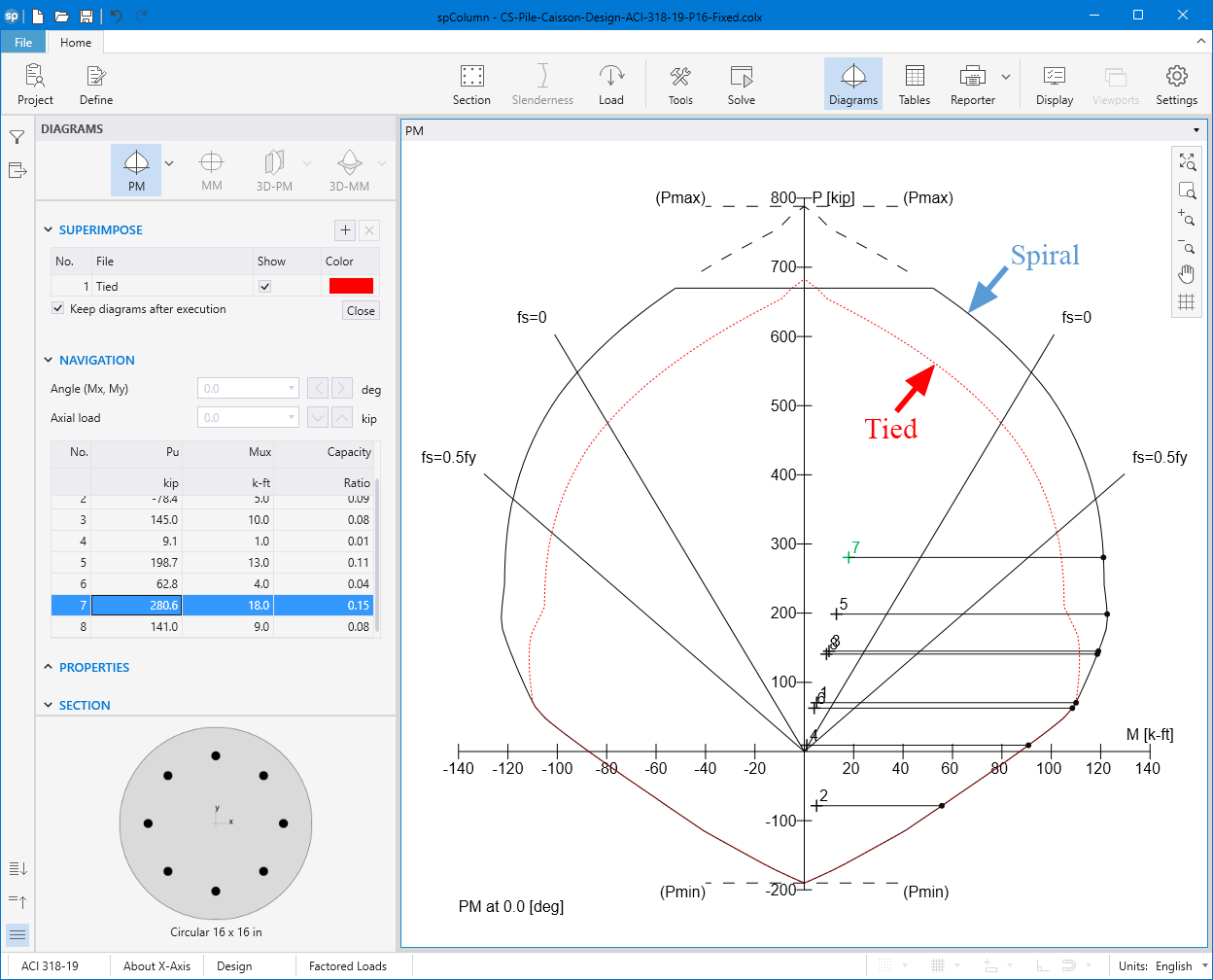
Additionally, spMats supports direct integration with spColumn by exporting pile and column data - including geometry, materials, and applied loads - into spColumn Text Input (CTI) files.
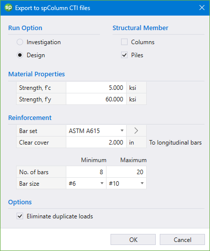
These files allow engineers to transition into detailed design and capacity checks for piles using spColumn's interaction diagrams and 3D failure surfaces.
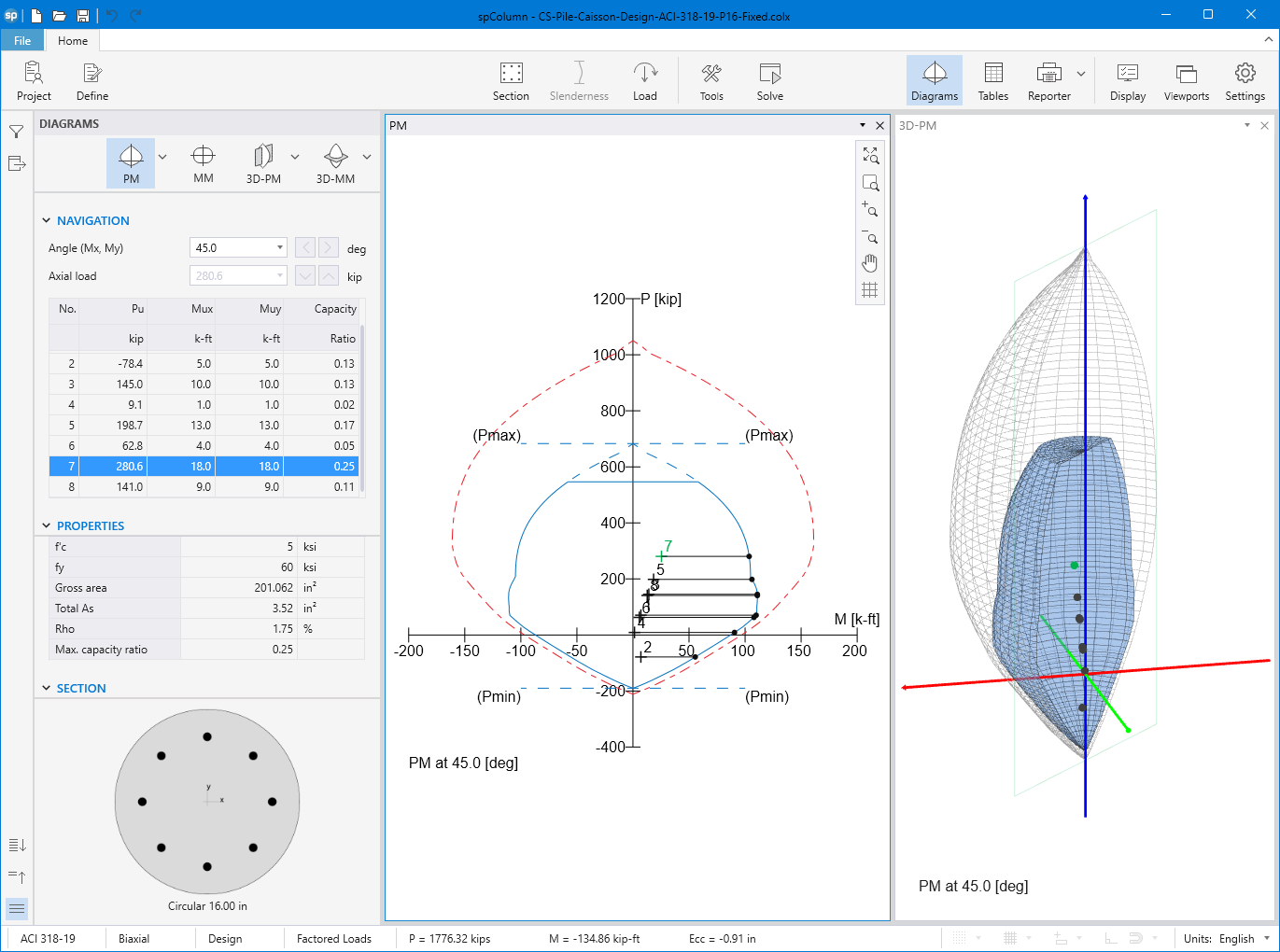
Whether piles are pinned or fixed to the cap, spMats and spColumn together enable full-cycle analysis and investigation, making them ideal tools for optimizing pile design.
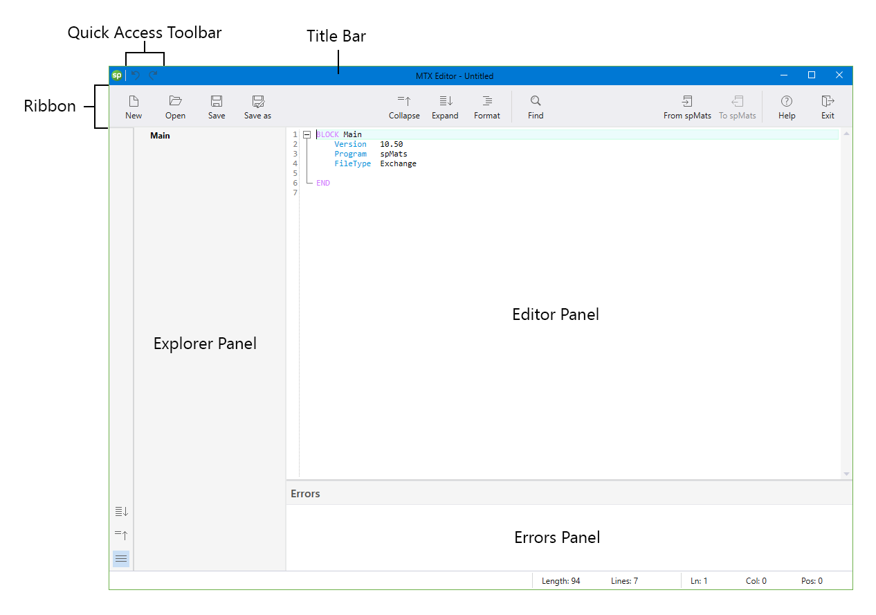
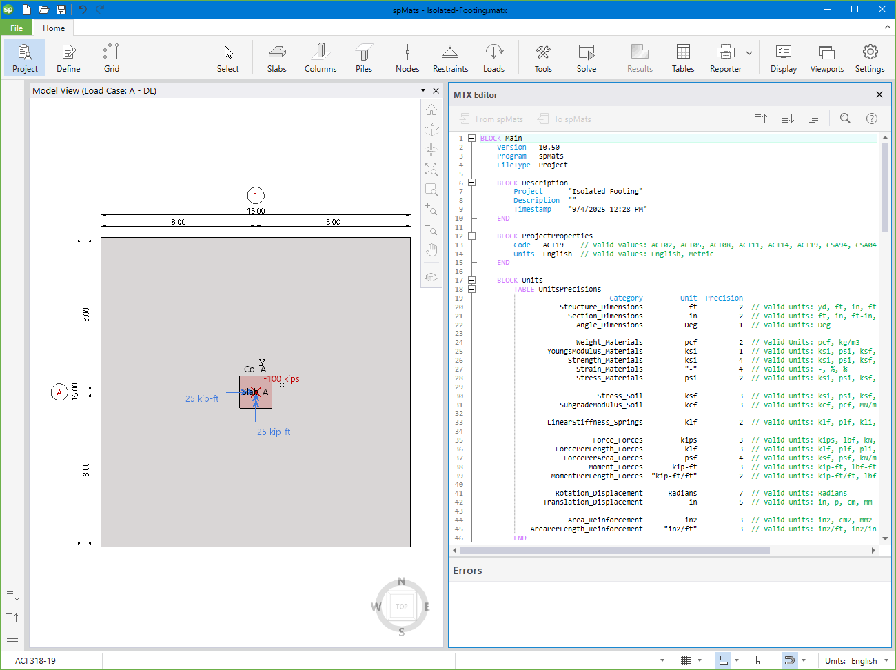
spMats Text Exchange (MTX) file format is the spTX (StructurePoint text Exchange) format adapted for spMats. MTX files follow all the rules, organization and formatting of spTX files. MTX files are plain text files and can be edited using the built in MTX editor in spMats program or by any other text editing software.
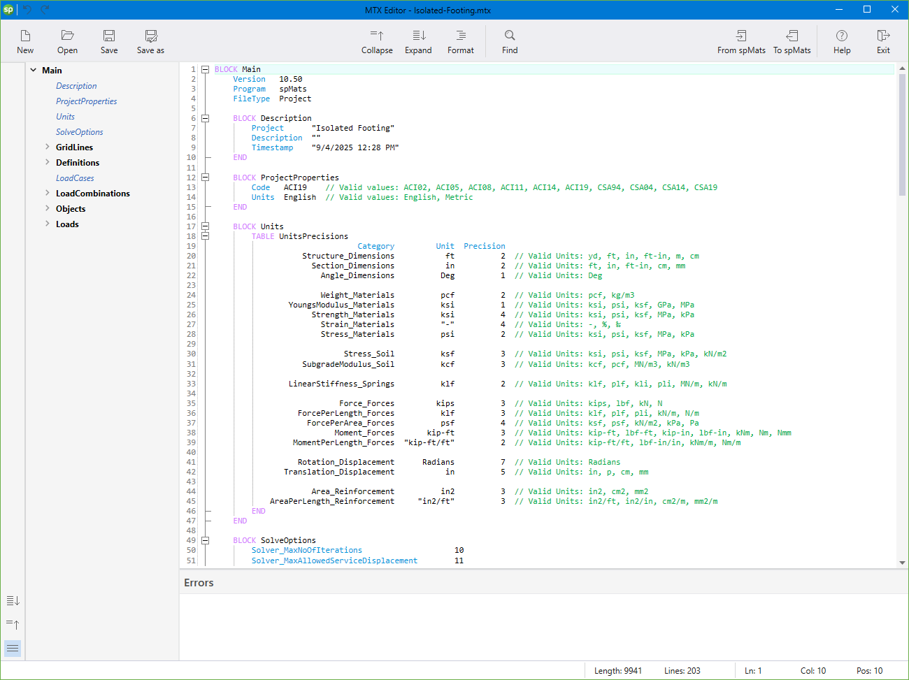
MTX files are designed to be human-readable. The user can easily read/modify an MTX file without using the spMats manual. The best way to create a MTX file is by using the spMats GUI. Users can either select the MTX file type in the Save As menu command to save the file as an MTX or open the spMats MTX editor and use the “From spMats” command to convert an existing project file into the MTX format. Creating an MTX file using the spMats GUI has an added advantage as MTX files created this way also list the valid values for each parameter and other required information as comments.
The "Auto Align" feature improves mesh quality by correcting misaligned nodes that create slender, high aspect ratio elements.
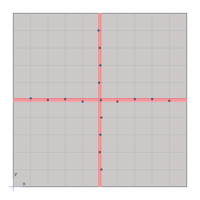
By setting a tolerance margin, and running "Auto Align", the program snaps nearby nodes to a common axis, producing a cleaner mesh and more reliable analysis.
The Reinforcement dropdown menu in the Display Options panel allows users to visually examine different reinforcement contour types. Users can select from Governing Value, Governing Type, Design, Base, Code Min., and Code Max. options.
All of these values are also summarized in a tabular results section called "Governing Reinforcement".
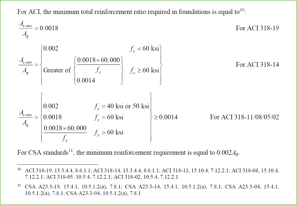
spMats allow users to check the minimum reinforcement ratios required by the selected code.
Users can also define a "Base" reinforcement ratio for each layer, to reflect practical detailing needs.
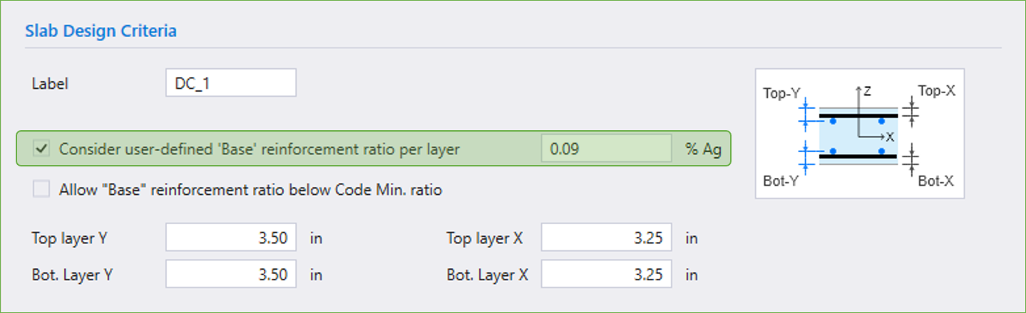
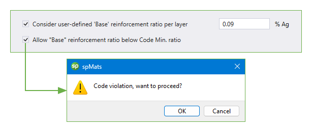
By default, if the "Base" is lower than the "code minimum", the design is capped at the code value.
If the user checks the box allowing the “Base” reinforcement ratio to fall below the code minimum, the program displays a warning indicating a code violation and advising caution.
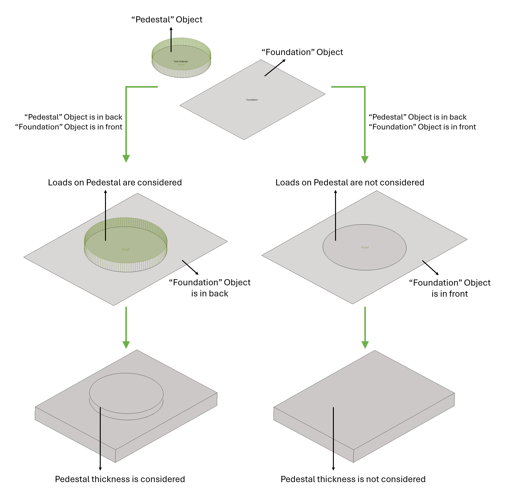
spMats, the inclusion of pedestal loads and thickness in the analysis depends on the order the objects are drawn in the model. If the pedestal object is set forward and the foundation object is backward, loads applied to the pedestal are properly considered, and its thickness is included in the model analysis. However, if the pedestal is drawn behind the foundation, the loads and thickness will be ignored in the analysis.
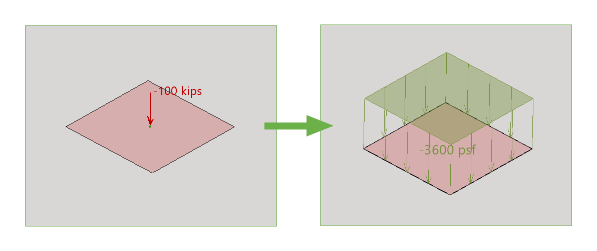
In spMats, point loads applied to a mat foundation can be redistributed as area loads to more accurately represent the load distribution. This approach is particularly useful when modeling heavy equipment, column reactions, or other concentrated loads that, in practice, are dispersed over a larger area due to the stiffness of the mat. To achieve this, users can define a load distribution area around the point load, allowing the program to evenly distribute the force across the specified area, resulting in more realistic stress and deflection results.
Ground supported slabs are frequently designed with a single layer of reinforcing. Such slabs are referred to as membrane slabs, floating slabs, or filler slabs and range in thickness from as little as 4" to 8" depending on the supported loads. In warehouses and storage facilities such slabs are subjected to concentrated point loads from storage rack posts or forklift wheel loads. By properly defining reinforcement parameters at the same horizontal plane for both top and bottom reinforcement layers, spMats provides powerful tools for the analysis and design of slabs on grade with single layer of reinforcement.
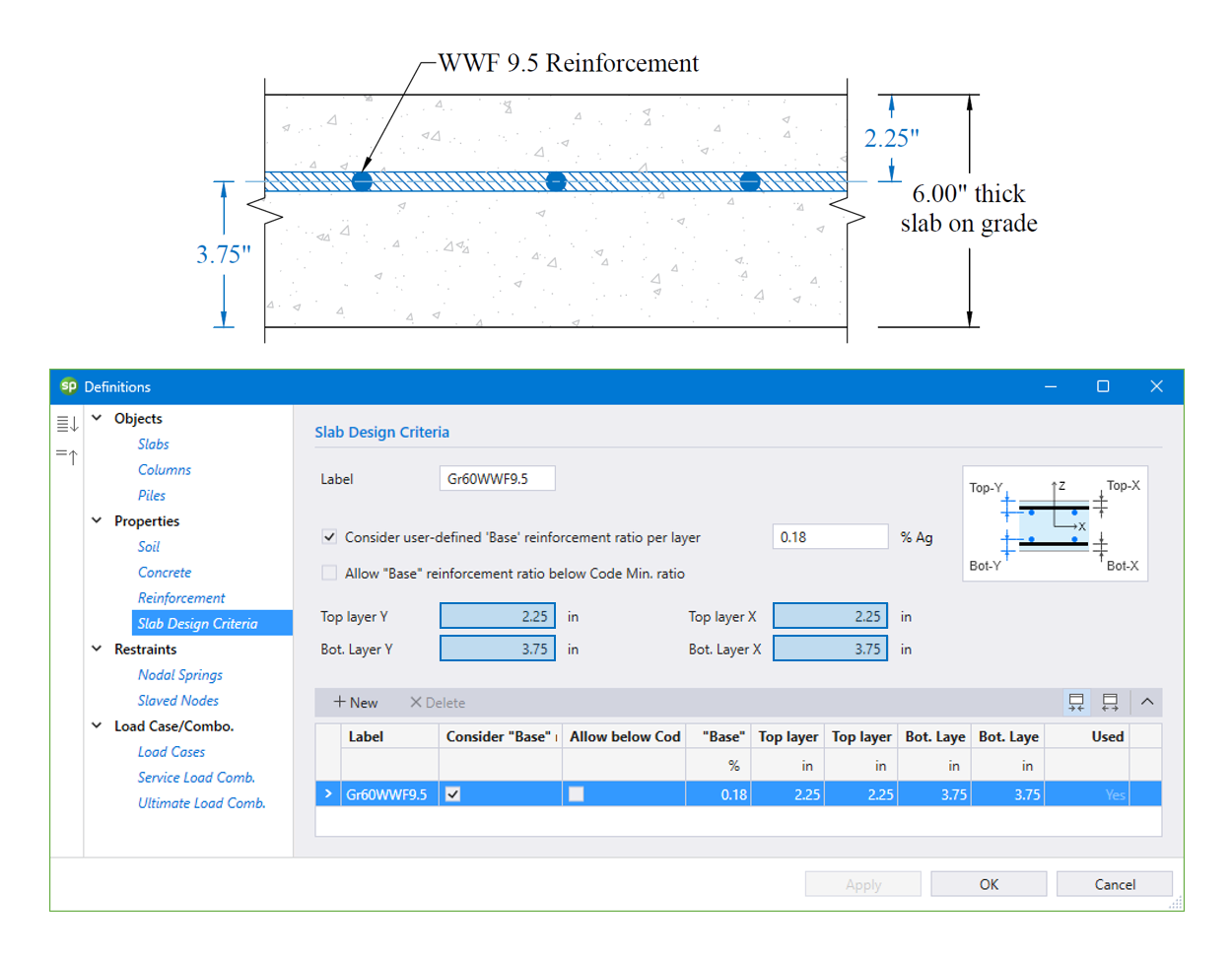
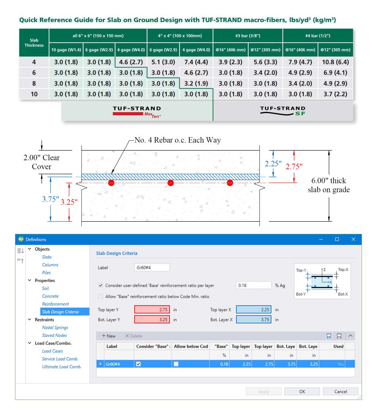
spMats enables engineers to model fiber-reinforced concrete slabs on grade by converting specified fiber dosages into equivalent single-layer reinforcement values. This approach allows accurate analysis of slab performance under concentrated loads, such as warehouse rack posts or forklift wheels.
Software
spColumn v10.30spMats v10.50spWall v10.20spSlab v10.00spBeam v10.00spFrame v1.50MaintenanceNetwork LicensingDownload & Buy
Buy Now! Download Trial Shopping Cart Pay Invoice